Harman Kardon AVR 2700 Service Manual
Hide thumbs
Also See for AVR 2700:
- Service manual (84 pages) ,
- Owner's manual (52 pages) ,
- Manual (11 pages)
Advertisement
Service Manual
ESD WARNING......................................2
LEAKAGE TESTING...............................3
BASIC SPECIFICATIONS.......................4
FRONT PANEL CONTROLS.....................5
REAR PANEL CONNECTIONS................7
REMOTE CONTROL FUNCTIONS........ ...9
CONNECTIONS/INSTALLATION..............14
OPERATION... . ... .. .. ...... .. . .............33
BASIC TROUBLESHOOTING..................41
PROCESSOR RESET.............................42
Released 2012
Discontinued XXXX
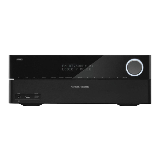
AVR 2700
Audio/Video Receiver
CONTENTS
8500 Balboa Blvd.
Northridge, CA. 91329
harman/kardon
AMPLIFIER BIAS ADJUSTMENT.............43
PACKAGING...........................................44
DISASSEMBLY....................................45
UNIT EXPLODED VIEW..........................46
BLOCK DIAGRAM.................................47
PCB DRAWINGS..................................49
ELECTRICAL PARTS LIST......................69
SEMICONDUCTOR PINOUTS...............138
SCHEMATICS.....................................139
WIRING DIAGRAM...............................158
Rev0 12/2012
Advertisement
Table of Contents

Related Manuals for Harman Kardon AVR 2700


Summary of Contents for Harman Kardon AVR 2700
-
Page 1: Table Of Contents
Service Manual harman/kardon AVR 2700 Audio/Video Receiver CONTENTS ESD WARNING…………………..……….2 AMPLIFIER BIAS ADJUSTMENT………….43 LEAKAGE TESTING……………….…..…..3 PACKAGING….…...……….………...………..44 BASIC SPECIFICATIONS…………………..4 DISASSEMBLY………………………………45 FRONT PANEL CONTROLS………..…..…..5 UNIT EXPLODED VIEW…………..…….…..46 REAR PANEL CONNECTIONS………….…7 BLOCK DIAGRAM………………….………..47 REMOTE CONTROL FUNCTIONS…….. …9 PCB DRAWINGS…………………….………49 CONNECTIONS/INSTALLATION……..14 ELECTRICAL PARTS LIST……..…….….…69 OPERATION…... - Page 2 AVR 2700 harman/kardon Some semiconductor (solid state) devices can be damaged easily by static electricity. Such components commonly are called Electrostatically Sensitive (ES) Devices. Examples of typical ES devices are integrated circuits and some field effect transistors and semiconductor "chip" components.
- Page 3 AVR 2700 harman/kardon SAFETY PRECAUTIONS The following check should be performed for the continued protection of the customer and service technician. LEAKAGE CURRENT CHECK Measure leakage current to a known earth ground (water pipe, conduit, etc.) by connecting a leakage current tester...
- Page 4 AVR 3700/AVR 370: 125W per channel, two channels driven @ 6/8 ohms, 20Hz – 20kHz, <0.07% THD Usable sensitivity (loop): 500µV AVR 2700/AVR 270: 105W per channel, two channels Distortion (1kHz, 50% mod): 1.0% driven @ 6/8 ohms, 20Hz – 20kHz, <0.07% THD Selectivity (±10kHz):...
-
Page 5: Front Panel Controls
AVR 2700 harman/kardon Front-Panel Controls Power Info Button Button Power Setup Message Volume Indicator Button Sensor Display Knob Resolution Video Back/Exit Source List Port Button Modes Button Button Button Button Headphone Jack/ HDMI ® Front Audio Surround Left/Right Up/Down EzSet/EQ... - Page 6 Resolution button: Press this button to access the AVR’s video output resolution setting: 480p (AVR 3700/AVR 2700), 576p (AVR 370/AVR 270), 720p, 1080i, 1080p or 1080p/24Hz. Use the Up/Down and OK buttons to change the setting.
-
Page 7: Rear Panel Connections
AVR 2700 harman/kardon Rear-Panel Connectors Wi-Fi Antenna Connector Analog Video (AVR 3700/AVR 370) Connectors Network Radio Antenna HDMI Output HDMI Input Connector Connectors Connectors Connectors Analog Audio Speaker Digital Audio AC Input IR and Trigger Connectors Connectors Connectors Vents Connector... - Page 8 AVR 2700 harman/kardon Subwoofer connector: Connect this jack to a powered subwoofer with a line-level input. Rear-Panel Connectors, continued See Connect Your Subwoofer, on page 17, for more information. NOTE: The AVR 3700 and AVR 370 have two subwoofer connectors.
-
Page 9: Remote Control Functions
AVR 2700 harman/kardon System Remote Control Functions IR Transmitter AVR Power On/Off Device Power Buttons On/Off Buttons Source Selector Buttons Audio Effects Surround Modes Button Button Video Modes Button Number Buttons Last Channel Activity Button Button Back/Exit Menu Button Button... -
Page 10: Operation
AVR 2700 harman/kardon Menu button: This button is used within the tuner menus and an iPod connected to the System Remote Control Functions, continued AVR’s front-panel USB port, and is also used to display the main menu on some source devices. -
Page 11: Processor Reset
AVR 2700 harman/kardon Recording Advanced Remote Control Programming Two-channel analog audio signals, as well as composite video signals, are normally available at the appropriate recording outputs. To make a recording, connect your audio Remote Channel-Control Punch-Through or video recorder to the appropriate AVR output connectors as described in the Making... - Page 12 AVR 2700 harman/kardon Zone 2 Remote Control Functions (AVR 3700/AVR 370 only) IR Transmitter Lens Power Off Mute Button Button Source Selector Buttons Sleep Button AVR Button Back/Exit Menu Button Button Up/Down/Left/Right Buttons OK Button Volume Up/Down Buttons Transport Control...
- Page 13 AVR 2700 harman/kardon Zone 2 Remote Control Functions (AVR 3700/AVR 370 only), continued By installing an IR receiver in the remote zone of a multizone system and connecting it to the AVR’s Zone 2 IR Input connector, you can use the Zone 2 remote to control the sound in the remote zone from within the remote zone.
- Page 14 AVR 2700 harman/kardon Connect Your Subwoofer Making Connections Use a single RCA audio cable to connect the AVR’s Subwoofer connector to your subwoofer as explained in Subwoofer Connections, on page 14. NOTE: The AVR 3700 and AVR 370 CAUTION: Before making any connections to the audio/video receiver, ensure provide connections for two subwoofers.
- Page 15 AVR 2700 harman/kardon Connect Your Audio and Video Source Devices However, you can connect your source devices as you wish and re-assign any of the input connections to any of the Source Buttons listed in the table according to where you Source devices are components where a playback signal originates, e.g.
- Page 16 AVR 2700 harman/kardon Connect Your HDMI Devices Connect Your Composite Video Devices If any of your source devices have HDMI connectors, using them will provide the best Use composite video connectors for video source devices that don’t have HDMI or possible video and audio performance quality.
- Page 17 AVR 2700 harman/kardon Connect Your Analog Audio Devices Connect Your Video Recorder Use the AVR’s analog audio connectors for source devices that don’t have HDMI or digital Connect an analog video recorder’s video input connector to the AVR’s Composite Monitor audio connectors.
- Page 18 AVR 2700 harman/kardon Connect to Your Home Network Install a Multizone System Use a Cat. 5 or Cat. 5E cable (not supplied) to connect the AVR’s Network connector to your home network to enjoy Internet radio and content from DLNA-compatible devices IMPORTANT SAFETY NOTE: Installing a multizone system typically requires that are connected to the network.
- Page 19 AVR 2700 harman/kardon B. Connect an external amplifier to the AVR’s Zone 2 Out connectors. This method Connect IR Equipment offers the benefit of retaining a 7.1-channel home theater in the main room simultaneously The AVR is equipped with Remote IR Input and Output connectors and a Zone 2 IR Input with multizone operation, although it does require an additional amplifier for Zone 2.
- Page 20 AVR 2700 harman/kardon To control more than one source device through the AVR’s IR Remote Out connector, Connect to AC Power connect all sources in “daisy chain” fashion, connecting each device’s IR output to the Connect the supplied AC power cord to the AVR’s AC Input connector and then to a next device’s IR input, starting with the AVR.
- Page 21 AVR 2700 harman/kardon 4. Aim the remote at the source device and use the remote’s Number buttons to enter a Set Up the Remote Control code number from Step 1, above. a) If the device turns off, press the Source Selector button again to save the code. The Install the Batteries in the Remote Control Source Selector button will flash, and the remote will exit the Programming mode.
- Page 22 AVR 2700 harman/kardon Learning (AVR 3700/AVR 370 only) If you have the device’s original remote control, you may “teach” its individual button codes into the following “destination” buttons on the AVR 3700/AVR 370 remote: Device Power On/Off buttons, Number buttons, Last button, Back/Exit button, Menu...
- Page 23 AVR 2700 harman/kardon The Main Menu system consists of six submenus: Source Select, Setup Source, Speaker Set Up the AVR Setup, Zone 2, System and Settings Lock. Use the Up/Down/Left/Right buttons on the remote or the front panel to navigate the menu system, and press the OK button to select In this section, you will configure the AVR to match your actual system’s makeup.
- Page 24 AVR 2700 harman/kardon 5. Press the remote control’s AVR button. The AVR’s on-screen display (OSD) Main Menu Set Up Your Sources screen will appear on the TV. The Setup Source menu lets you assign the correct physical audio and video connections to each source and lets you set many audio and video playback features for each source.
- Page 25 find the HDMI Bypass mode acceptable for normal 2D viewing as well must set the resolution to “480i” (AVR 3700/AVR 2700) or to “576p” (AVR 370/AVR as for 3D viewing. In this case, you may find it more convenient to use the 3D 270) to view any content.
- Page 26 AVR 2700 harman/kardon Wired Network Setup The following options appear in the Wireless Setup menu: If your network uses an automatic IP address, you should not have to perform any Search AP: Select this option to display and select the wireless network you wish network setup procedures for a wired network connection.
- Page 27 AVR 2700 harman/kardon Step Three – Manual Speaker Setup Menu Manual Speaker Setup Now you are ready to program the receiver. Sit in your usual listening position, and make Your AVR is flexible and may be configured to work with most speakers and to compensate the room as quiet as possible.
- Page 28 AVR 2700 harman/kardon Any changes will be reflected in the total Number Of Speakers displayed at the top of Sub Mode the screen. Move the cursor to the Sub Mode line. This setting depends upon the Crossover setting The Assigned AMP setting includes four options: you selected for the front left and right speakers.
- Page 29 AVR 2700 harman/kardon Step Four – Setting Channel Output Levels Manually Reset Levels: To reset all levels to their factory defaults of 0dB, scroll down to this line at the bottom of the menu and press the OK button. For a conventional stereo receiver, a simple balance control adjusts the stereo imaging by varying the relative loudness of the left and right channels.
- Page 30 AVR 2700 harman/kardon Listening in Zone 2 With the multizone system in use, you may enjoy an exciting 5.1-channel home theater presentation in the main listening area, while others listen to the same program or an entirely different source in another room. See Install a Multizone System, on page 21, for installation information.
- Page 31 AVR 2700 harman/kardon CEC Power Control: This setting links the power on/off functions of the AVR to those of a System Settings TV connected to its HDMI Monitor Out connector. When Power Control is set to On, turning the TV’s power off will automatically put the AVR into the Standby mode; turning the TV’s The AVR’s System Settings menu lets you customize in what way many of the AVR’s...
-
Page 32: Released
AVR 2700 harman/kardon Volume Units: This setting lets you select whether the AVR displays the volume level in Settings Lock the conventional decibel scale or on a numeric scale from 0 to 100. When the decibel Settings Lock prevents the Setup Source, Speaker Setup and System settings menus scale is used, 0dB is the maximum recommended volume, with lower volumes displayed from being inadvertently changed. - Page 33 Both Modeler and Leveler modules are active; Medium AVR 2700 and AVR 270 receivers that are connected to the same network as the device Leveler module has a value of 3 that has the app installed. With this easy-to-use app you can turn the AVR on or off, select Both Modeler and Leveler modules are active;...
- Page 34 AVR 2700 harman/kardon Selecting a Source Listening to FM and AM Radio There are three different ways to select a source: Select the Radio source. A screen similar to the one in the illustration below will appear. Press the front-panel Source List button. Use the Up/Down buttons to scroll through the sources, and press the OK button to select the source being displayed.
- Page 35 AVR 2700 harman/kardon Playing files on a USB device Listening to an iPod/iPhone/iPad Device 1. Insert the USB drive into the AVR’s front-panel USB port. When an iPod, iPhone or iPad device is connected to the AVR’s front-panel USB port, you may play audio files through your high-quality audio system, operate the iPod, iPad or...
- Page 36 AVR 2700 harman/kardon If a video monitor is connected to the AVR and the system is not in iPod manual mode, Listening to vTuner (Internet Radio) an iPod screen will appear and display the play mode icon, song title, artist and album. A Your AVR’s Network connection brings you a world of MP3- and WMA-format streams via...
- Page 37 AVR 2700 harman/kardon To share media on PCs: Stereo: When you want two-channel playback, select the number of speakers you want to use for playback: 1. Open Windows Media Player. “2 CH Stereo” uses two speakers. 2. Open the Library menu and select Media Sharing. The Media Sharing window will appear.
- Page 38 AVR 2700 harman/kardon The second number indicates whether any surround channels are present: “0” indicates Advanced Functions that no surround information is present. “1” indicates that a matrixed surround signal is present. “2” indicates discrete left and right surround channels. “3” is used with DTS-ES Much of the adjusting and configuration your AVR requires is handled automatically, with...
- Page 39 AVR 2700 harman/kardon Audio Effects Button Treble/Bass: These settings boost or cut the treble or bass frequencies by up to 10dB. Use the Left/Right buttons to change the setting. The default setting is 0dB, at the center To adjust other audio settings, such as the tone controls, press the Audio Effects of the bar.
- Page 40 AVR 2700 harman/kardon How to Adjust the Custom Picture Settings Sharpness Adjustment Set the Video Mode to Custom to display the picture settings. Contrary to intuition, the picture will appear sharper and clearer with the sharpness backed off from the maximum setting. Reduce the Sharpness setting on your television, Video Modes –...
- Page 41 AVR 2700 harman/kardon Symptom Cause Solution Unit does not function when Main Power switch is turned on power outlet Front-panel Message display lights, but there’s no sound or picture No sound from any speaker; PROTECT message appears on Message display...
- Page 42 AVR 2700 harman/kardon Reset Proceedure To restore the AVR to factory defaults (reset) press & hold Surround Mode Key about 5sec, when AVR's in eco stand by. !!Warning!! This will erase all of the user programmed settings and pre sets.
- Page 43 AVR 2700 harman/kardon AMPLIFIER SECTION BIAS ADJUSTMENT Measurement condition .No input signal or volume position is minimum. .Do not adjust at FM/ AM. Standard value .Ideal current = 48mA ( .Ideal DC Voltage = 22.5mV ( DC EVM PCB) CN66...
- Page 44 AVR 2700 harman/kardon...
- Page 45 AVR 2700 harman/kardon DISASSEMBLY AVR2700 1. Removing the Top Cabinet 3. Removing the Rear Panel Remove the Screws Remove the Screws 25 26 4. Removing the Main PCB Remove the Screws 2. Removing the Front Panel Remove the Screws...
- Page 46 AVR 2700 harman/kardon AVR270/230 EXPLODE VIEW AVR2700 KCA-11 UCD-11A CRE1A108 (KCA-34) 46-4 46-3 46-2 44-2 44-1 PARTS NO. Q,ty REMARK NO DESCRIPTION AVR270/230 AVR2700 KNOB,VOLUME CBN1A269B65 INDICATOR,VOLUME CGL1A300 CGB3A158Z BADGE, HARMAN/KARDON 46-1 SHEET,AL FRONT CGX6A390C82Z WINDOW,FIP CGU2A410A25H 44-4 BADGE,AVR3700 CGB1A249Z...
- Page 47 AVR 2700 harman/kardon AVR2700/3700 Block Diagram ADV3002 ADV7850 ADC & ADV3002 2D/3D Decoder Only AVR370 HDMI Fast Switch HDMI Rx ADV8195 HDMI BUFFER ADV8003 Video Processor 4k2k bypass Audio Out Up/down scaling RJ 45 Bridge Co DM860(Only AVR270) CX870 (Only AVR370) SPI (OSD) GPIO&...
- Page 48 AVR 2700 harman/kardon AVR2700/3700 Block Diagram (DSP Part) To HDMI / BCO SPDIF & Analog Audio S I/F By Upgrade SPI & GPIO UART & GPIO AZ4580 DSP DOWNMIX REC DOWNMIX DAI 1 DA0 2 CS497024 USB ? GPIO DAI 2...
- Page 49 AVR 2700 harman/kardon...
- Page 50 AVR 2700 harman/kardon...
- Page 51 AVR 2700 harman/kardon...
- Page 52 AVR 2700 harman/kardon...
- Page 53 AVR 2700 harman/kardon...
- Page 54 AVR 2700 harman/kardon...
- Page 55 AVR 2700 harman/kardon...
- Page 56 AVR 2700 harman/kardon...
- Page 57 AVR 2700 harman/kardon...
- Page 58 AVR 2700 harman/kardon...
- Page 59 AVR 2700 harman/kardon...
- Page 60 AVR 2700 harman/kardon...
- Page 61 AVR 2700 harman/kardon...
- Page 62 AVR 2700 harman/kardon...
- Page 63 AVR 2700 harman/kardon...
- Page 64 AVR 2700 harman/kardon...
- Page 65 AVR 2700 harman/kardon...
- Page 66 AVR 2700 harman/kardon...
- Page 67 AVR 2700 harman/kardon...
- Page 68 AVR 2700 harman/kardon...
- Page 69 CGR1A539 FRONT PANEL ASS'Y CGWAVR2700 KNOB , STANDBY CBT2A1064 KNOB , BACK CBT2A1065 BADGE , AVR2700 CGB1A252Z BADGE , HARMAN/KARDON (FRONT) CGB3A158Z INDICATOR , POWER AVR155 CGL1A265Y ORNAMENT , RING CGR1A538G5 WINDOW , FIP CGU2A410A25O PANEL , FRONT AVR270/230 CGW1A527RHYB24...
- Page 70 AVR 2700 harman/kardon CHASSIS , BOTTOM CUA2A337 INLET WIRE ASS'Y CWZAVR2700CN90A CN10 WIRE ASS'Y (3P, 150mm) CWB1B003150LL F901 FUSE(215Series, 250V/8A) KBA2C8000TLHEY SW91 SW , ROCKER ASS'Y CSH2B026ZA AVR2700 DIGITAL PCB ASS'Y COP12457D AVR270 MAIN PCB ASS'Y COP12459D AVR2700/3700 JACK PCB ASS'Y...
- Page 71 AVR 2700 harman/kardon C452 CAP, ELECT(16V/100uF) CCEA1CH101TC C453 CAP , ELECT(63V/47uF),105'C CCEA1JH470TCS C454 CAP , POLYESTER FILM(250V/0.027UF, 5%) CCME2E273JX14T C455 CAP, ELECT(16V/100uF) CCEA1CH101TC C721 CAP, ELECT(50V/2.2uF) S CCEA1HKS2R2TC C731 CAP, ELECT(10V/470uF) CCEA1AH471TC C811 CAP, ELECT(50V/10uF) CCEA1HH100TC C823 CAP, ELECT(50V/10uF) CCEA1HH100TC...
- Page 72 AVR 2700 harman/kardon J151 WIRE, COPPER(D0.6) C3A206 0.018 J152 WIRE, COPPER(D0.6) C3A206 0.022 J153 WIRE, COPPER(D0.6) C3A206 0.022 J154 WIRE, COPPER(D0.6) C3A206 0.027 J155 WIRE, COPPER(D0.6) C3A206 0.027 J156 WIRE, COPPER(D0.6) C3A206 0.022 J157 WIRE, COPPER(D0.6) C3A206 0.022 J158 WIRE, COPPER(D0.6) C3A206 0.022...
- Page 73 AVR 2700 harman/kardon S318 SW , TACT CST1A024ZT S319 SW , TACT CST1A024ZT S320 SW , TACT CST1A024ZT S321 SW , TACT CST1A024ZT S322 SW , TACT CST1A024ZT S323 SW , TACT CST1A024ZT S330 SW , TACT CST1A024ZT C121 CAP, CHIP(1608, 50V/150pF)
- Page 74 AVR 2700 harman/kardon Q114 T.R,RT1N144C(10K 47K) CVTRT1N144C Q252 T.R,RT1N144C(10K 47K) CVTRT1N144C Q721 T.R,RT1N144C(10K 47K) CVTRT1N144C Q906 T.R,RT1P144C(10K 47K) CVTRT1P144C Q907 T.R,RT1P144C(10K 47K) CVTRT1P144C Q955 T.R,RT1N144C(10K 47K) CVTRT1N144C R101 RES, CHIP(1608/5%/220ohm) CRJ10DJ221T R102 RES, CHIP(1608/5%/680ohm) CRJ10DJ681T R104 RES, CHIP(1608/5%/10Kohm) CRJ10DJ103T R108...
- Page 75 AVR 2700 harman/kardon R644 RES, CHIP(1608/5%/0ohm) CRJ10DJ0R0T R645 RES, CHIP(1608/5%/0ohm) CRJ10DJ0R0T R701 RES, CHIP(1608/5%/1Kohm) CRJ10DJ102T R702 RES, CHIP(1608/5%/1Kohm) CRJ10DJ102T R703 RES, CHIP(1608/5%/1Kohm) CRJ10DJ102T R711 RES, CHIP(1608/5%/47ohm) CRJ10DJ470T R712 RES, CHIP(1608/5%/47ohm) CRJ10DJ470T R713 RES, CHIP(1608/5%/47ohm) CRJ10DJ470T R721 RES, CHIP(1608/5%/10Kohm) CRJ10DJ103T R722...
- Page 76 AVR 2700 harman/kardon C501 CAP, CHIP(2012, 6.3V/10uF, X7R) CCUC0J106KC C502 CAP, CHIP(1608, 10V/1uF) CCUS1A105KC C503 CAP, CHIP(1608, 50V/0.1uF) CCUS1H104KC C504 CAP, CHIP(2012, 6.3V/10uF, X7R) CCUC0J106KC C505 CAP, CHIP(2012, 6.3V/10uF, X7R) CCUC0J106KC C507 CAP, CHIP(1608, 50V/0.1uF) CCUS1H104KC IC501 IC, CURRENT LIMIT, 2A...
- Page 77 AVR 2700 harman/kardon C3934 CAP, CHIP(1005, 16V/0.1uF) CCUI1C104KC C3935 CAP, CHIP(1005, 16V/0.1uF) CCUI1C104KC C3936 CAP, CHIP(1005, 16V/0.1uF) CCUI1C104KC C3937 CAP, CHIP(1005, 16V/0.1uF) CCUI1C104KC C3938 CAP, CHIP(1005, 16V/0.1uF) CCUI1C104KC C3939 CAP, CHIP(1005, 16V/0.1uF) CCUI1C104KC C3944 CAP, CHIP(1608, 6.3V/4.7uF, MURATA GRM18) CCUS0J475KC C3947 CAP, CHIP(1608, 6.3V/4.7uF, MURATA GRM18)
- Page 78 AVR 2700 harman/kardon R3969 RES, CHIP(1005/5%/33ohm*4) CRJ064IJ330T R3984 RES, CHIP(1005/5%/47ohm) CRJ06IJ470T C3213 CAP, CHIP(1608, 6.3V/4.7uF, MURATA GRM18) CCUS0J475KC C3900 CAP, CHIP(1005, 50V/1000pF) CCUI1H102KC C3901 CAP, CHIP(1608, 50V/8pF) CCUS1H080DA C3902 CAP, CHIP(1608, 50V/8pF) CCUS1H080DA C3905 CAP, CHIP(1608, 6.3V/4.7uF, MURATA GRM18) CCUS0J475KC...
- Page 79 AVR 2700 harman/kardon R3973 RES, CHIP(1005/5%/4.7Kohm) CRJ06IJ472T R3974 RES, CHIP(1005/5%/1.5Kohm) CRJ06IJ152T R3975 RES, CHIP(1005/5%/1Kohm) CRJ06IJ102T R3976 RES, CHIP(1005/5%/12Kohm) CRJ06IJ123T X3900 X TAL, SMD 3.2X2.5, 24.000MHz, 8PF COX24000I080ST DIGITAL PCB ASS'Y (COP12457D) Description Parts No. CN53 PIN SOCKET,SMD(14PIN,2.54mm,8.5mm Height,STRAIGHT) CJP14GA300ZB CN54 PIN SOCKET,SMD(22PIN,2.54mm,8.5mm Height,STRAIGHT)
- Page 80 AVR 2700 harman/kardon C1253 CAP, CHIP(1005, 16V/0.1uF) CCUI1C104KC C1254 CAP, CHIP(1005, 25V/0.01uF) CCUI1E103KC C1255 CAP, CHIP(1005, 25V/0.01uF) CCUI1E103KC C1256 CAP, CHIP(1005, 25V/0.01uF) CCUI1E103KC C1257 CAP, CHIP(1005, 16V/0.1uF) CCUI1C104KC C1258 CAP, CHIP(1005, 16V/0.1uF) CCUI1C104KC C1259 CAP, CHIP(1005, 16V/0.1uF) CCUI1C104KC C1260 CAP, CHIP(1005, 16V/0.1uF)
- Page 81 AVR 2700 harman/kardon C1315 CAP, CHIP(1005, 16V/0.1uF) CCUI1C104KC C1316 CAP, CHIP(1005, 16V/0.1uF) CCUI1C104KC C1317 CAP, CHIP(1005, 16V/0.1uF) CCUI1C104KC C1318 CAP, CHIP(1005, 16V/0.1uF) CCUI1C104KC C1319 CAP, CHIP(1005, 16V/0.1uF) CCUI1C104KC C1320 CAP, CHIP(2012, 6.3V/10uF, X7R) CCUC0J106KC C1321 CAP, CHIP(1005, 16V/0.1uF) CCUI1C104KC C1322 CAP, CHIP(1005, 16V/0.1uF)
- Page 82 AVR 2700 harman/kardon C1447 CAP, CHIP(1005, 16V/0.1uF) CCUI1C104KC C1448 CAP, CHIP(1005, 16V/0.1uF) CCUI1C104KC C1449 CAP, CHIP(1005, 16V/0.1uF) CCUI1C104KC C1450 CAP, CHIP(1005, 25V/0.01uF) CCUI1E103KC C1451 CAP, CHIP(1005, 16V/0.1uF) CCUI1C104KC C1452 CAP, CHIP(1005, 25V/0.01uF) CCUI1E103KC C1453 CAP, CHIP(2012, 6.3V/10uF, X7R) CCUC0J106KC C1454 CAP, CHIP(1005, 16V/0.1uF)
- Page 83 AVR 2700 harman/kardon C1528 CAP, CHIP(1005, 16V/0.1uF) CCUI1C104KC C1529 CAP, CHIP(1005, 16V/0.1uF) CCUI1C104KC C1530 CAP, CHIP(1005, 16V/0.1uF) CCUI1C104KC C1531 CAP, CHIP(1005, 16V/0.1uF) CCUI1C104KC C1532 CAP, CHIP(1005, 16V/0.1uF) CCUI1C104KC C1533 CAP, CHIP(1005, 16V/0.1uF) CCUI1C104KC C1534 CAP, CHIP(1005, 16V/0.1uF) CCUI1C104KC C1535 CAP, CHIP(1005, 16V/0.1uF)
- Page 84 AVR 2700 harman/kardon C1777 CAP, CHIP(2012, 10V/22uF) CCUC1A226KC C1778 CAP, CHIP(1608, 50V/0.1uF) CCUS1H104KC C1779 CAP, CHIP(2012, 10V/22uF) CCUC1A226KC C1780 CAP, CHIP(1608, 50V/0.1uF) CCUS1H104KC C1782 CAP, CHIP(1608, 50V/0.1uF) CCUS1H104KC C1789 CAP, CHIP(2012, 10V/22uF) CCUC1A226KC C1804 CAP, CHIP(2012, 6.3V/10uF, X7R) CCUC0J106KC C1805 CAP, CHIP(1608, 50V/0.1uF)
- Page 85 AVR 2700 harman/kardon C1975 CAP, CHIP(1608, 50V/0.1uF) CCUS1H104KC C1977 CAP, CHIP(1608, 50V/0.1uF) CCUS1H104KC C1979 CAP, CHIP(1608, 50V/0.1uF) CCUS1H104KC C1980 CAP, CHIP(1608, 50V/0.1uF) CCUS1H104KC C1981 CAP, CHIP(1608, 50V/0.1uF) CCUS1H104KC C1982 CAP, CHIP(1608, 50V/0.1uF) CCUS1H104KC C1983 CAP, CHIP(1608, 50V/0.1uF) CCUS1H104KC C1985 CAP, CHIP(1608, 50V/0.1uF)
- Page 86 AVR 2700 harman/kardon C2212 CAP, CHIP(1608, 50V/0.01uF) CCUS1H103KC C2213 CAP, CHIP(1608, 50V/0.01uF) CCUS1H103KC C2219 CAP, CHIP(1608, 50V/0.068uF) CCUS1H683KC C2220 CAP, CHIP(1608, 50V/2700pF) CCUS1H272KC C2222 CAP, CHIP(1608, 50V/8200pF) CCUS1H822KC C2223 CAP, CHIP(1608, 50V/390pF) CCUS1H391JA C2225 CAP, CHIP(1608, 50V/0.01uF) CCUS1H103KC C2226 CAP, CHIP(1608, 50V/0.01uF)
- Page 87 AVR 2700 harman/kardon IC1711 I.C , OPAMP(DUAL/LOW NOISE)_Copper CVIAZ4580MTR E1 CU IC1714 I.C , 2CH DAC(32BIT,384KHZ,TSSOP 20P) CVIPCM5100PWR IC1906 I.C , DAC(192kHz STEREO DAC /TSSOP 10) CVICS4344CZZR IC1911 I.C , SERIAL FLASH(8M) CVIMX25L8006EM2I 12G IC2102 I.C , RESET (2.8V , SOT 89)
- Page 88 AVR 2700 harman/kardon Q2211 T.R,RT1N144C(10K 47K) CVTRT1N144C Q2212 T.R,RT1P144C(10K 47K) CVTRT1P144C Q2213 T.R,RT1N144C(10K 47K) CVTRT1N144C T.R,RT1P144C(10K 47K) CVTRT1P144C RN1207 RES, CHIP(1005/5%/47ohm*4) CRJ064IJ470T RN1208 RES, CHIP(1005/5%/47ohm*4) CRJ064IJ470T RN1411 RES, CHIP(1005/5%/47ohm*4) CRJ064IJ470T RN1413 RES, CHIP(1005/5%/47ohm*4) CRJ064IJ470T RN1904 RES, CHIP(1005/5%/33ohm*4) CRJ064IJ330T RN1916 RES, CHIP(1608/5%/10Kohm*4)
- Page 89 AVR 2700 harman/kardon R1218 RES, CHIP(1005/5%/680ohm) CRJ06IJ681T R1219 RES, CHIP(1608/5%/0ohm) CRJ10DJ0R0T R1220 RES, CHIP(1608/5%/24ohm) CRJ10DJ240T R1222 RES, CHIP(1608/5%/24ohm) CRJ10DJ240T R1224 RES, CHIP(1608/5%/24ohm) CRJ10DJ240T R1226 RES, CHIP(1608/5%/24ohm) CRJ10DJ240T R1228 RES, CHIP(1608/5%/51ohm) CRJ10DJ510T R1230 RES, CHIP(1608/5%/51ohm) CRJ10DJ510T R1232 RES, CHIP(1608/5%/51ohm) CRJ10DJ510T R1234...
- Page 90 AVR 2700 harman/kardon R1478 RES, CHIP(1608/1%/470ohm) CRJ10DF4700T R1479 RES, CHIP(1005/5%/1.8Kohm) CRJ06IJ182T R1480 RES, CHIP(1005/5%/1.8Kohm) CRJ06IJ182T R1483 RES, CHIP(1608/5%/5.1ohm) CRJ10DJ5R1T R1485 RES, CHIP(1608/1%/51ohm) CRJ10DF51R0T R1486 RES, CHIP(1608/1%/51ohm) CRJ10DF51R0T R1493 RES, CHIP(1005/5%/47ohm) CRJ06IJ470T R1494 RES, CHIP(1005/5%/47ohm) CRJ06IJ470T R1495 RES, CHIP(1005/5%/47ohm) CRJ06IJ470T R1496...
- Page 91 AVR 2700 harman/kardon R1904 RES, CHIP(1608/5%/4.7Kohm) CRJ10DJ472T R1906 RES, CHIP(1608/5%/2.7Kohm) CRJ10DJ272T R1907 RES, CHIP(1608/5%/2.7Kohm) CRJ10DJ272T R1908 RES, CHIP(1608/5%/4.7Kohm) CRJ10DJ472T R1909 RES, CHIP(1608/5%/3.9Kohm) CRJ10DJ392T R1912 RES, CHIP(1608/5%/4.7Kohm) CRJ10DJ472T R1913 RES, CHIP(1608/5%/2.7Kohm) CRJ10DJ272T R1915 RES, CHIP(1608/5%/2.7Kohm) CRJ10DJ272T R1916 RES, CHIP(1608/5%/2.7Kohm) CRJ10DJ272T R1917...
- Page 92 AVR 2700 harman/kardon R2122 RES, CHIP(1608/5%/100ohm) CRJ10DJ101T R2131 RES, CHIP(1608/5%/0ohm) CRJ10DJ0R0T R2134 RES, CHIP(1608/5%/10Kohm) CRJ10DJ103T R2135 RES, CHIP(1608/5%/10Kohm) CRJ10DJ103T R2149 RES, CHIP(1608/5%/100ohm) CRJ10DJ101T R2150 RES, CHIP(1608/5%/47Kohm) CRJ10DJ473T R2151 RES, CHIP(1608/5%/2.7Kohm) CRJ10DJ272T R2152 RES, CHIP(1608/5%/2.7Kohm) CRJ10DJ272T R2159 RES, CHIP(1608/5%/2.2Kohm) CRJ10DJ222T R2160 RES, CHIP(1608/5%/2.2Kohm)
- Page 93 AVR 2700 harman/kardon R2251 RES, CHIP(1608/5%/100ohm) CRJ10DJ101T R2252 RES, CHIP(1608/5%/100Kohm) CRJ10DJ104T R2253 RES, CHIP(1608/5%/100Kohm) CRJ10DJ104T R2254 RES, CHIP(1608/5%/100ohm) CRJ10DJ101T R2255 RES, CHIP(1608/5%/3.3Kohm) CRJ10DJ332T R2261 RES, CHIP(1608/5%/3.3Kohm) CRJ10DJ332T R2263 RES, CHIP(1608/5%/6.8Kohm) CRJ10DJ682T R2264 RES, CHIP(1608/5%/0ohm) CRJ10DJ0R0T R2265 RES, CHIP(1608/5%/1.5Kohm) CRJ10DJ152T R2266 RES, CHIP(1608/5%/1.5Kohm)
- Page 94 AVR 2700 harman/kardon R2333 RES, CHIP(1608/5%/47Kohm) CRJ10DJ473T R2334 RES, CHIP(1608/5%/2.2Kohm) CRJ10DJ222T R2335 RES, CHIP(1608/5%/1.5Kohm) CRJ10DJ152T R2336 RES, CHIP(1608/5%/1.2Kohm) CRJ10DJ122T R2337 RES, CHIP(1608/5%/5.6Kohm) CRJ10DJ562T R2338 RES, CHIP(1608/5%/47Kohm) CRJ10DJ473T R2339 RES, CHIP(1608/5%/47Kohm) CRJ10DJ473T R2340 RES, CHIP(1608/5%/560ohm) CRJ10DJ561T R2341 RES, CHIP(1608/5%/560ohm) CRJ10DJ561T R2343 RES, CHIP(1608/5%/3.9Kohm)
- Page 95 AVR 2700 harman/kardon CN20 PIN SOCKET,SMD(32PIN,2.54mm,8.5mm Height,STRAIGHT) CJP32GA300ZB CN21 PIN SOCKET,SMD(30PIN,2.54mm,8.5mm Height,STRAIGHT) CJP30GA300ZB CN52 WAFER, 20037WR NN Series, 2mm, SMD, ANGLE, 15P CJP15GB276ZY CN76 WAFER, 2mm, SMD, Vertical, 07p CJP07GA208ZY C100 CAP, CHIP(1608, 50V/0.1uF) CCUS1H104KC C1001 CAP, CHIP(1005, 16V/0.1uF) CCUI1C104KC C1002 CAP, CHIP(1005, 16V/0.1uF)
- Page 96 AVR 2700 harman/kardon C1516 CAP, CHIP(1608, 10V/1uF) CCUS1A105KC C1520 CAP, CHIP(1608, 50V/0.1uF) CCUS1H104KC C1538 CAP, CHIP(1005, 16V/0.1uF) CCUI1C104KC C1556 CAP, CHIP(1005, 16V/0.1uF) CCUI1C104KC C1560 CAP, CHIP(2012, 6.3V/10uF, X7R) CCUC0J106KC C1561 CAP, CHIP(2012, 6.3V/10uF, X7R) CCUC0J106KC C1610 CAP, CHIP(2012, 6.3V/10uF, X7R)
- Page 97 AVR 2700 harman/kardon C1798 CAP, CHIP(1608, 50V/0.015uF) CCUS1H153KC C1799 CAP, CHIP(2012, 10V/22uF) CCUC1A226KC C1800 CAP, CHIP(1608, 50V/0.01uF) CCUS1H103KC C1802 CAP, CHIP(2012, 10V/22uF) CCUC1A226KC C1803 CAP, CHIP(1608, 50V/0.1uF) CCUS1H104KC C1806 CAP,ALUMINUM ELECTROLYTIC (6.3V/47uF) CCEC0JMVG470T C1812 CAP, CHIP(1608, 50V/0.1uF) CCUS1H104KC C1813 CAP, CHIP(1608, 50V/0.1uF)
- Page 98 AVR 2700 harman/kardon C1912 CAP, CHIP(1608, 50V/100pF) CCUS1H101JA C1913 CAP, CHIP(1608, 50V/2700pF) CCUS1H272KC C1914 CAP, CHIP(1608, 50V/0.1uF) CCUS1H104KC C1916 CAP,ALUMINUM ELECTROLYTIC (16V/10uF) CCEC1CMVG100T C1920 CAP, CHIP(2012, 10V/22uF) CCUC1A226KC C1922 CAP, CHIP(2012, 6.3V/10uF, X7R) CCUC0J106KC C1924 CAP,ALUMINUM ELECTROLYTIC (16V/10uF) CCEC1CMVG100T C1925...
- Page 99 AVR 2700 harman/kardon C2217 CAP, CHIP(1608, 50V/8200pF) CCUS1H822KC C2218 CAP, CHIP(1608, 50V/390pF) CCUS1H391JA C2221 CAP, CHIP(1608, 50V/0.1uF) CCUS1H104KC C2224 CAP,ALUMINUM ELECTROLYTIC (16V/10uF) CCEC1CMVG100T C2227 CAP,ALUMINUM ELECTROLYTIC (16V/10uF) CCEC1CMVG100T C2228 CAP, CHIP(1608, 50V/0.1uF) CCUS1H104KC C2229 CAP, CHIP(1608, 50V/2700pF) CCUS1H272KC C2230 CAP, CHIP(1608, 50V/2700pF)
- Page 100 AVR 2700 harman/kardon C2332 CAP,ALUMINUM ELECTROLYTIC (16V/10uF) CCEC1CMVG100T C2333 CAP,ALUMINUM ELECTROLYTIC (16V/10uF) CCEC1CMVG100T C2334 CAP,ALUMINUM ELECTROLYTIC (16V/10uF) CCEC1CMVG100T C2335 CAP,ALUMINUM ELECTROLYTIC (16V/10uF) CCEC1CMVG100T C2336 CAP,ALUMINUM ELECTROLYTIC (16V/10uF) CCEC1CMVG100T C2401 CAP,ALUMINUM ELECTROLYTIC (16V/10uF) CCEC1CMVG100T C2402 CAP,ALUMINUM ELECTROLYTIC (16V/10uF) CCEC1CMVG100T C2407 CAP,ALUMINUM ELECTROLYTIC (16V/10uF)
- Page 101 AVR 2700 harman/kardon IC2215 IC, REGULATOR(1A, 8V) CVILM7808RTRL IC2216 IC, REGULATOR(1A, 8V) CVILM7908RTRL IC2218 T.R , CHIP(TS6) HVTKTC812TB IC2219 T.R , CHIP(TS6) HVTKTC812TB JK1001 JACK, HDMI(TYPE A, SMT 19P) CJJ9H008Y JK1002 JACK, HDMI(TYPE A, SMT 19P) CJJ9H008Y JK1003 JACK, HDMI(TYPE A, SMT 19P)
- Page 102 AVR 2700 harman/kardon L1730 FERRITE CHIP BEAD(4516/60R) CLZ9Z014Z L1733 FERRITE CHIP BEAD(4516/60R) CLZ9Z014Z L1734 FERRITE CHIP BEAD(4516/60R) CLZ9Z014Z L1735 FERRITE CHIP BEAD(4516/60R) CLZ9Z014Z L1736 FERRITE CHIP BEAD(4516/60R) CLZ9Z014Z L1737 COIL,SMD POWER(1.5uH/2A) CLQ18E1R5NRZ L1738 COIL,SMD POWER(1.5uH/2A) CLQ18E1R5NRZ L1739 COIL,SMD POWER(1.5uH/2A) CLQ18E1R5NRZ L1740 COIL,SMD POWER(1.5uH/2A)
- Page 103 AVR 2700 harman/kardon RN1417 RES, CHIP(1005/5%/47ohm*4) CRJ064IJ470T RN1418 RES, CHIP(1005/5%/47ohm*4) CRJ064IJ470T RN1419 RES, CHIP(1005/5%/47ohm*4) CRJ064IJ470T RN1420 RES, CHIP(1005/5%/47ohm*4) CRJ064IJ470T RN1421 RES, CHIP(1005/5%/47ohm*4) CRJ064IJ470T RN1422 RES, CHIP(1005/5%/47ohm*4) CRJ064IJ470T RN1423 RES, CHIP(1005/5%/47ohm*4) CRJ064IJ470T RN1424 RES, CHIP(1005/5%/47ohm*4) CRJ064IJ470T RN1901 RES, CHIP(1005/5%/33ohm*4) CRJ064IJ330T RN1902...
- Page 104 AVR 2700 harman/kardon R1105 RES, CHIP(1005/5%/47Kohm) CRJ06IJ473T R1106 RES, CHIP(1005/5%/100ohm) CRJ06IJ101T R1107 RES, CHIP(1005/5%/47Kohm) CRJ06IJ473T R1108 RES, CHIP(1005/5%/1Kohm) CRJ06IJ102T R1109 RES, CHIP(1005/5%/22Kohm) CRJ06IJ223T R1110 RES, CHIP(1005/5%/4.7Kohm) CRJ06IJ472T R1111 RES, CHIP(1005/5%/47Kohm) CRJ06IJ473T R1112 RES, CHIP(1005/5%/100ohm) CRJ06IJ101T R1113 RES, CHIP(1005/5%/47Kohm) CRJ06IJ473T R1114...
- Page 105 AVR 2700 harman/kardon R1449 RES, CHIP(1005/5%/0ohm) CRJ06IJ0R0T R1450 RES, CHIP(1005/5%/0ohm) CRJ06IJ0R0T R1466 RES, CHIP(1608/1%/1.37Kohm) CRJ10DF1371T R1467 RES, CHIP(1608/1%/2.2Kohm) CRJ10DF2201T R1489 RES, CHIP(1608/5%/0ohm) CRJ10DJ0R0T R1490 RES, CHIP(1608/5%/0ohm) CRJ10DJ0R0T R1491 RES, CHIP(1005/5%/47ohm) CRJ06IJ470T R1492 RES, CHIP(1005/5%/47ohm) CRJ06IJ470T R1501 RES, CHIP(1005/5%/10Kohm) CRJ06IJ103T R1505...
- Page 106 AVR 2700 harman/kardon R1715 RES, CHIP(1608/1%/14.3Kohm) CRJ10DF1432T R1716 RES, CHIP(1608/1%/18Kohm) CRJ10DF1802T R1717 RES, CHIP(1608/5%/10Kohm) CRJ10DJ103T R1718 RES, CHIP(1608/1%/14.3Kohm) CRJ10DF1432T R1719 RES, CHIP(1608/1%/18Kohm) CRJ10DF1802T R1720 RES, CHIP(1608/5%/10Kohm) CRJ10DJ103T R1721 RES, CHIP(1608/1%/14.3Kohm) CRJ10DF1432T R1722 RES, CHIP(1608/1%/18Kohm) CRJ10DF1802T R1723 RES, CHIP(1608/5%/10Kohm) CRJ10DJ103T R1724 RES, CHIP(1608/1%/14.3Kohm)
- Page 107 AVR 2700 harman/kardon R1952 RES, CHIP(1608/5%/10Kohm) CRJ10DJ103T R1953 RES, CHIP(1608/5%/0ohm) CRJ10DJ0R0T R1959 RES, CHIP(1608/5%/33ohm) CRJ10DJ330T R1960 RES, CHIP(1608/5%/33ohm) CRJ10DJ330T R1961 RES, CHIP(1608/5%/33ohm) CRJ10DJ330T R1962 RES, CHIP(1608/5%/33ohm) CRJ10DJ330T R1963 RES, CHIP(1608/5%/33ohm) CRJ10DJ330T R1967 RES, CHIP(1608/5%/33ohm) CRJ10DJ330T R1968 RES, CHIP(1608/5%/33ohm) CRJ10DJ330T R1969...
- Page 108 AVR 2700 harman/kardon R2164 RES, CHIP(1608/5%/10Kohm) CRJ10DJ103T R2165 RES, CHIP(1608/5%/47Kohm) CRJ10DJ473T R2167 RES, CHIP(1608/5%/10Kohm) CRJ10DJ103T R2168 RES, CHIP(1608/5%/10Kohm) CRJ10DJ103T R2172 RES, CHIP(1608/5%/10Kohm) CRJ10DJ103T R2176 RES, CHIP(1608/5%/10Kohm) CRJ10DJ103T R2177 RES, CHIP(1608/5%/10Kohm) CRJ10DJ103T R2178 RES, CHIP(1608/5%/0ohm) CRJ10DJ0R0T R2179 RES, CHIP(1608/5%/0ohm) CRJ10DJ0R0T R2182...
- Page 109 AVR 2700 harman/kardon MAIN PCB ASS'Y (COP12459D) Description Parts No. BN14 WIRE ASS'Y (2.5MM, 180MM, 7PIN, DUAL DIPPING TYPE) CWB1D00718088 BN15 WIRE ASS'Y (2.5mm, 150mm, 9pin, Dual dipping type) CWB1D00915088 BN20 WIRE ASS'Y CWB3FE03200UZ BN25 WIRE ASS'Y(#18,2P,120mm, 3.96mm Dual dipping type)
- Page 110 AVR 2700 harman/kardon C561 CAP, ELECT(16V/100uF) CCEA1CH101TC C562 CAP, ELECT(16V/100uF) CCEA1CH101TC C563 CAP, ELECT(16V/100uF) CCEA1CH101TC C564 CAP, ELECT(16V/100uF) CCEA1CH101TC C565 CAP, ELECT(16V/100uF) CCEA1CH101TC C566 CAP, ELECT(16V/100uF) CCEA1CH101TC C567 CAP, ELECT(16V/100uF) CCEA1CH101TC C568 CAP, ELECT(16V/100uF) CCEA1CH101TC C569 CAP, ELECT(16V/100uF) CCEA1CH101TC C570...
- Page 111 AVR 2700 harman/kardon C816 CAP , CERAMIC(330PF/50V) CCBS1H331KBT C817 CAP, ELECT(50V/10uF) CCEA1HH100TC C818 CAP, ELECT(50V/10uF) CCEA1HH100TC C819 CAP , CERAMIC(270PF/50V) CCBS1H271KBT C820 CAP , CERAMIC(270PF/50V) CCBS1H271KBT C851 CAP, ELECT(50V/10uF) CCEA1HH100TC C852 CAP, ELECT(50V/10uF) CCEA1HH100TC C853 CAP, ELECT(50V/10uF) CCEA1HH100TC C854 CAP, ELECT(50V/10uF)
- Page 112 AVR 2700 harman/kardon D954 DIODE , RECT CVD1N4003SRT D955 DIODE , RECT CVD1N4003SRT ET90 PLATE , EARTH(TRONIC ELECTRONICS) CJT1A026 ET91 PLATE , EARTH(TRONIC ELECTRONICS) CJT1A026 J106 WIRE, COPPER(D0.6) C3A206 0.018 J107 WIRE, COPPER(D0.6) C3A206 0.018 J109 WIRE, COPPER(D0.6) C3A206 0.018 J110 WIRE, COPPER(D0.6)
- Page 113 AVR 2700 harman/kardon J173 WIRE, COPPER(D0.6) C3A206 0.018 J175 WIRE, COPPER(D0.6) C3A206 0.018 J176 WIRE, COPPER(D0.6) C3A206 0.018 J177 WIRE, COPPER(D0.6) C3A206 0.018 J178 WIRE, COPPER(D0.6) C3A206 0.018 J179 WIRE, COPPER(D0.6) C3A206 0.018 J181 WIRE, COPPER(D0.6) C3A206 0.018 J182 WIRE, COPPER(D0.6) C3A206 0.018...
- Page 114 AVR 2700 harman/kardon J344 WIRE, COPPER(D0.6) C3A206 0.022 J346 WIRE, COPPER(D0.6) C3A206 0.022 J348 WIRE, COPPER(D0.6) C3A206 0.022 J352 WIRE, COPPER(D0.6) C3A206 0.022 J404 WIRE, COPPER(D0.6) C3A206 0.025 J405 WIRE, COPPER(D0.6) C3A206 0.025 J406 WIRE, COPPER(D0.6) C3A206 0.02 J501 WIRE, COPPER(D0.6) C3A206 0.027...
- Page 115 AVR 2700 harman/kardon J806 WIRE, COPPER(D0.6) C3A206 0.037 J808 WIRE, COPPER(D0.6) C3A206 0.022 J809 WIRE, COPPER(D0.6) C3A206 0.037 J810 WIRE, COPPER(D0.6) C3A206 0.02 J811 WIRE, COPPER(D0.6) C3A206 0.018 J813 WIRE, COPPER(D0.6) C3A206 0.018 J816 WIRE, COPPER(D0.6) C3A206 0.02 J817 WIRE, COPPER(D0.6) C3A206 0.02...
- Page 116 AVR 2700 harman/kardon Q505 PNP, TO 92, LOW NOISE, HFE:300 600, FAILCHILD CVTKSA992FTA Q508 T.R , MUTE HVTKTC2874BT Q509 T.R , MUTE HVTKTC2874BT Q511 NPN, TO 92, LOW NOISE, HFE:300 600, FAILCHILD CVTKSC1845FTA Q512 NPN, TO 92, LOW NOISE, HFE:300 600, FAILCHILD...
- Page 117 AVR 2700 harman/kardon Q950 HVTKTA1266YT Q961 HVTKTA1024YT R501 RES, CARBON(1/5W,43Kohm,J) CRD20TJ433T R502 RES, CARBON(1/5W,43Kohm,J) CRD20TJ433T R503 RES, CARBON(1/5W,43Kohm,J) CRD20TJ433T R504 RES, CARBON(1/5W,43Kohm,J) CRD20TJ433T R505 RES, CARBON(1/5W,43Kohm,J) CRD20TJ433T R506 RES, CARBON(1/5W,27Kohm,J) CRD20TJ273T R507 RES, CARBON(1/5W,27Kohm,J) CRD20TJ273T R508 RES, CARBON(1/5W,27Kohm,J) CRD20TJ273T R509...
- Page 118 AVR 2700 harman/kardon R567 RES, CARBON(1/5W,560ohm,J) CRD20TJ561T R568 RES, CARBON(1/5W,560ohm,J) CRD20TJ561T R569 RES, CARBON(1/5W,560ohm,J) CRD20TJ561T R570 RES, CARBON(1/5W,560ohm,J) CRD20TJ561T R571 RES, CARBON(1/5W,560ohm,J) CRD20TJ561T R572 RES, CARBON(1/5W,560ohm,J) CRD20TJ561T R573 RES, CARBON(1/5W,560ohm,J) CRD20TJ561T R574 RES, CARBON(1/5W,560ohm,J) CRD20TJ561T R575 RES, CARBON(1/5W,560ohm,J) CRD20TJ561T R576...
- Page 119 AVR 2700 harman/kardon R647 RES , CARBON CRD25FJ3R3T R648 RES , CARBON CRD25FJ3R3T R649 RES , CARBON CRD25FJ3R3T R650 RES , CARBON CRD25FJ3R3T R651 RES , CARBON CRD25FJ3R3T R652 RES , CARBON CRD25FJ3R3T R653 RES , CARBON CRD25FJ3R3T R654 RES , CARBON...
- Page 120 AVR 2700 harman/kardon R736 RES, M OXIDE FILM(2W/0.47ohm) CRG2SANJR47RT R737 RES, M OXIDE FILM(2W/0.47ohm) CRG2SANJR47RT R738 RES, M OXIDE FILM(2W/0.47ohm) CRG2SANJR47RT R739 RES, M OXIDE FILM(2W/0.47ohm) CRG2SANJR47RT R740 RES, M OXIDE FILM(2W/0.47ohm) CRG2SANJR47RT R741 RES, M OXIDE FILM(2W/0.47ohm) CRG2SANJR47RT R742 RES, M OXIDE FILM(2W/0.47ohm)
- Page 121 AVR 2700 harman/kardon R840 RES, CARBON(1/5W,560ohm,J) CRD20TJ561T R841 RES, CARBON(1/5W,560ohm,J) CRD20TJ561T R842 RES, CARBON(1/5W,560ohm,J) CRD20TJ561T R843 RES, CARBON(1/5W,560ohm,J) CRD20TJ561T R844 RES, CARBON(1/5W,560ohm,J) CRD20TJ561T R845 RES, CARBON(1/5W,560ohm,J) CRD20TJ561T R848 RES, CARBON(1/5W,27Kohm,J) CRD20TJ273T R849 RES, CARBON(1/5W,27Kohm,J) CRD20TJ273T R850 RES, CARBON(1/5W,1.8Kohm,J) CRD20TJ182T R851 RES, CARBON(1/5W,1.8Kohm,J)
- Page 122 AVR 2700 harman/kardon R924 RES, CARBON(1/5W,47Kohm,J) CRD20TJ473T R925 RES, CARBON(1/5W,47Kohm,J) CRD20TJ473T R926 RES, CARBON(1/5W,47Kohm,J) CRD20TJ473T R928 RES, CARBON(1/5W,2.2Kohm,J) CRD20TJ222T R929 RES, CARBON(1/5W,2.2Kohm,J) CRD20TJ222T R930 RES, CARBON(1/5W,2.2Kohm,J) CRD20TJ222T R941 RES, CARBON(1/5W,10Kohm,J) CRD20TJ103T R942 RES, CARBON(1/5W,10Kohm,J) CRD20TJ103T R943 RES, CARBON(1/5W,10Kohm,J) CRD20TJ103T R944...
- Page 123 AVR 2700 harman/kardon Q940 High Voltage PNP Transistors(SOT 23) CVTMMBT5401 Q941 High Voltage NPN Transistors(SOT 23) CVTMMBT5551 Q942 High Voltage NPN Transistors(SOT 23) CVTMMBT5551 Q943 High Voltage NPN Transistors(SOT 23) CVTMMBT5551 Q951 High Voltage NPN Transistors(SOT 23) CVTMMBT5551 Q952 High Voltage NPN Transistors(SOT 23)
- Page 124 AVR 2700 harman/kardon SOLDER , FLUX WIRE PB FREE(PIE 1.0) C2K86102 TAPE , BOTH SIDE C4FM073 0.02 FLUX C8E534 BN53 PIN HEADER, DIP(14P, 2.54mm, H :36.9mm, STRAIGHT) CJP14GA301ZB BN54 PIN HEADER, DIP(22P, 2.54mm, H :36.9mm, STRAIGHT) CJP22GA301ZB BN55 PIN HEADER, DIP(8P, 2.54mm, H :36.9mm, STRAIGHT)
- Page 125 AVR 2700 harman/kardon J132 WIRE, COPPER(D0.6) C3A206 0.022 J133 WIRE, COPPER(D0.6) C3A206 0.025 J134 WIRE, COPPER(D0.6) C3A206 0.027 J135 WIRE, COPPER(D0.6) C3A206 0.018 J136 WIRE, COPPER(D0.6) C3A206 0.025 J137 WIRE, COPPER(D0.6) C3A206 0.025 J138 WIRE, COPPER(D0.6) C3A206 0.037 J139 WIRE, COPPER(D0.6) C3A206 0.027...
- Page 126 AVR 2700 harman/kardon C302 CAP, CHIP(1608, 50V/220pF) CCUS1H221JA C303 CAP, CHIP(1608, 50V/220pF) CCUS1H221JA C304 CAP, CHIP(1608, 50V/220pF) CCUS1H221JA C305 CAP, CHIP(1608, 50V/220pF) CCUS1H221JA C306 CAP, CHIP(1608, 50V/220pF) CCUS1H221JA C310 CAP, CHIP(1608, 50V/0.1uF) CCUS1H104KC C312 CAP, CHIP(1608, 50V/0.1uF) CCUS1H104KC C322 CAP, CHIP(1608, 50V/0.1uF)
- Page 127 AVR 2700 harman/kardon R311 RES, CHIP(1608/5%/100Kohm) CRJ10DJ104T R312 RES, CHIP(1608/5%/100Kohm) CRJ10DJ104T R313 RES, CHIP(1608/5%/100Kohm) CRJ10DJ104T R314 RES, CHIP(1608/5%/100Kohm) CRJ10DJ104T R321 RES, CHIP(1608/5%/4.7Kohm) CRJ10DJ472T R322 RES, CHIP(1608/5%/4.7Kohm) CRJ10DJ472T R323 RES, CHIP(1608/5%/4.7Kohm) CRJ10DJ472T R324 RES, CHIP(1608/5%/100ohm) CRJ10DJ101T R325 RES, CHIP(1608/5%/0ohm) CRJ10DJ0R0T R326...
- Page 128 AVR 2700 harman/kardon BK52 BRACKET , HDMI CMD1A787 C3002 CAP, CHIP(1005, 16V/0.1uF) CCUI1C104KC C3003 CAP, CHIP(1005, 16V/0.1uF) CCUI1C104KC C3004 CAP, CHIP(1005, 16V/0.1uF) CCUI1C104KC C3005 CAP, CHIP(1005, 16V/0.1uF) CCUI1C104KC C3007 CAP, CHIP(1005, 16V/0.1uF) CCUI1C104KC C3008 CAP, CHIP(1005, 16V/0.1uF) CCUI1C104KC C3009 CAP, CHIP(1005, 16V/0.1uF)
- Page 129 AVR 2700 harman/kardon CY93 CAP , CERAMIC (400V Y CAP) CCKDHS102ME CY94 CAP , CERAMIC (400V Y CAP) CCKDHS471ME CY95 CAP , CERAMIC (400V Y CAP) CCKDHS102ME CY96 CAP , CERAMIC (400V Y CAP) CCKDHS222ME C901 CAP , ELECT (470uF/250V, 105'C, 25.4X35)
- Page 130 AVR 2700 harman/kardon PC91 I.C , PHOTO COUPLER CVIEL817B PC92 I.C , PHOTO COUPLER CVIEL817B PC93 I.C , PHOTO COUPLER CVIEL817B PC94 I.C , PHOTO COUPLER CVIEL817B PC95 I.C , PHOTO COUPLER CVIEL817B PC96 I.C , PHOTO COUPLER CVIEL817B PC99 I.C , PHOTO COUPLER...
- Page 131 AVR 2700 harman/kardon J909 WIRE, COPPER(D0.6) C3A206 0.022 J910 WIRE, COPPER(D0.6) C3A206 0.022 J911 WIRE, COPPER(D0.6) C3A206 0.02 J912 WIRE, COPPER(D0.6) C3A206 0.022 J913 WIRE, COPPER(D0.6) C3A206 0.02 J914 WIRE, COPPER(D0.6) C3A206 0.025 J915 WIRE, COPPER(D0.6) C3A206 0.022 J916 WIRE, COPPER(D0.6) C3A206 0.02...
- Page 132 AVR 2700 harman/kardon J968 WIRE, COPPER(D0.6) C3A206 0.025 J969 WIRE, COPPER(D0.6) C3A206 0.027 J971 WIRE, COPPER(D0.6) C3A206 0.02 J972 WIRE, COPPER(D0.6) C3A206 0.02 J973 WIRE, COPPER(D0.6) C3A206 0.02 J974 WIRE, COPPER(D0.6) C3A206 0.02 J975 WIRE, COPPER(D0.6) C3A206 0.025 J976 WIRE, COPPER(D0.6) C3A206 0.02...
- Page 133 AVR 2700 harman/kardon D901 DIODE, SURFACE MOUNT RECTIFIER(1000V/1A) CVDS1M D902 DIODE, SURFACE MOUNT RECTIFIER(1000V/1A) CVDS1M D903 DIODE , ULTRA FAST RECTIFIER CVDUS1M D904 DIODE , ULTRA FAST RECTIFIER CVDUS1M D905 DIODE , ULTRA FAST RECTIFIER CVDUS1M D907 DIODE , ZENER(20V/0.5W, SOD 123)
- Page 134 AVR 2700 harman/kardon R891 RES, CHIP(3216/1%/56Kohm) CRJ14CF5602T R892 RES, CHIP(2012/1%/270Kohm) CRJ18AF2703T R893 RES, CHIP(2012/1%/56Kohm) CRJ18AF5602T R894 RES, CHIP(2012/5%/180ohm) CRJ18AJ181T R895 RES, CHIP(2012/5%/180ohm) CRJ18AJ181T R896 RES, CHIP(2012/1%/15Kohm) CRJ18AF1502T R897 RES, CHIP(3216/5%/0ohm) CRJ14CJ0R0T R904 RES, CHIP(3216/5%/0ohm) CRJ14CJ0R0T R906 RES, CHIP(2012/5%/33ohm) CRJ18AJ330T R907...
- Page 135 AVR 2700 harman/kardon R969 RES, CHIP(2012/5%/0ohm) CRJ18AJ0R0T R970 RES, CHIP(2012/5%/10ohm) CRJ18AJ100T R971 RES, CHIP(2012/5%/10ohm) CRJ18AJ100T R972 RES, CHIP(2012/5%/10ohm) CRJ18AJ100T R973 RES, CHIP(6432/5%/100ohm) CRJ01HJ101T R974 RES, CHIP(3216/5%/75Kohm) CRJ14CJ753T R975 RES, CHIP(3216/5%/75Kohm) CRJ14CJ753T R976 RES, CHIP(3216/5%/75Kohm) CRJ14CJ753T R978 RES, CHIP(6432/5%/100ohm) CRJ01HJ101T R979...
-
Page 136: Packaging
AVR 2700 harman/kardon D947 DIODE , ULTRA FAST RECTIFIER CVDUS1M D948 DIODE , ZENER(24V/0.5W, SOD 123) CVDMM1Z24H D949 DIODE , FAST SWITCHING(0.5W, SOD 123) CVD1N4448W D951 DIODE , ULTRA FAST RECTIFIER CVDUS1M Q902 T.R (NPN, SOT 23, ISAHAYA) CVT2SC6046T1121W Q904 T.R,RT1N141C(10K 10K) - Page 137 AVR 2700 harman/kardon FM 1 POLE ANT(UL) CSA1A019Z ANT, AM LOOP(9.5uH/5T) CSA1A039Z...
-
Page 138: Block Diagram
AVR 2700 harman/kardon TRANSISTOR, REGULATOR IC BLOCK DIAGRAM TO-92L TO-92M TO-92 TO-220 1. Emitter 1. Emitter 1. Emitter 1. GND 2. Collector 2. Collector 2. Collector 2. INPUT 3. Base 3. Base 3. Base 3. OUTPUT KTA1024Y KSC2316Y KTC2874B KSC2785Y... -
Page 139: Schematics
AVR 2700 harman/kardon R3902 33X4 DEBUG_TX DEBUG_TX ETDO DEBUG_RX DEBUG_RX ETDI ETCK ETMS DM_D0 R3961 DM_D1 DEBUG_TX 33X4 DM_D2 DEBUG_RX DM_D3 E_RXDMOEI DM_D4 E_TXDMIEO NC_01 256M SDRAM NC_02 R3962 DM_D5 NC_03 NC_04 33X4 C3952 1000P IC392 R3903 33X4 DM_D6 NC_05... - Page 140 AVR 2700 harman/kardon BCO_3.3V CX870 Low Density Connector 1.GND 2.GND 3.3.3V E_RXDMOEI R3101 4.RXD0 5.3.3V E_TXDMIEO R3102 6.TXD0 BCO_1.2V 7.GND 8.GND 9.1.9V 10.1.2V 11.1.9V 12.1.2V 13.GND 14.GND 15.NWAIT DEBUG_RX R3103 16.RXD1 17.NCS2 DEBUG_TX R3104 18.TXD1 E_RESET 19.NREST 20.GND 21.3.3V_RTC E_256FS R3105 22.MCLK...
- Page 141 AVR 2700 harman/kardon AVR270/AVR370 SMPS SUB SCHEMATIC DIAGRAM SN92 SN93 R951 D945 R902 D906 SAUXB SAUXA US1M US1M D951 D919 R999 R918 US1M US1M 100K 100K SHVB SHVA SFBA SFBB SPGND SPGND C933 D948 C909 D909 0 ohm 0 ohm...
- Page 142 AVR 2700 harman/kardon...
- Page 143 AVR 2700 harman/kardon ADV7630 3.3V Decoupling Capacitor AVDD_3V3_3002_M2 CUP12457Z Worst Measured Currents +3.3V_MUX L1001 170mA (561mW) 9R005Z Q1001 #21: HPD Part Q1002 T1P141C HDMI_3_RX_HPD I2C_ADDR[1] I2C_ADDR[0] --> ADDR T1N241C R1003 HP DET 0x90 R1006 HDMI_3_RX_PWR C1001 R1005 0x92 1005 / 1/16W / 0ohm AVDD_3V3_3002_M2 0.1uF / 16V...
- Page 144 AVR 2700 harman/kardon CUP12457Z ADV7630 3.3V Decoupling Capacitor Q1101 #21: HPD Part AVDD_3V3_3002_M1 Q1102 Worst Measured Currents +3.3V_MUX L1101 170mA (561mW) T1P141C HDMI_7_RX_HPD 9R005Z R1103 T1N241C HP DET R1106 HDMI_7_RX_PWR C1101 R1105 0.1uF / 16V DDC DATA HDMI_7_RX_DDC_SDA DDC CLK...
- Page 145 AVR 2700 harman/kardon DDR_VREF DDR2 Memory (ADV7850 Used) IC1202 AVRx70 -> 8P Analog Video IN/OUT CVIK4T51163QI-HCE7 CUP12457Z VREF SDRAM_DQ0 SDRAM_DQ1 SDRAM_DQ5 SDRAM_DQ2 SDRAM_DQ0 SDRAM_A0 SDRAM_DQ3 CHGND SDRAM_A1 SDRAM_DQ4 SDRAM_DQ7 SDRAM_A2 SDRAM_DQ5 CVBS1 CVBS1 SDRAM_A3 SDRAM_DQ6 DQ13 SDRAM_A4 SDRAM_DQ7 SDRAM_DQ13 CHGND...
- Page 146 AVR 2700 harman/kardon +1.8V_SCALER ADV8003_DVDD_1.8V 1.8V Power Supply 3.3V Power Supply DDR2 Memory layout Guidelines: ADV8003_AVDD2_3.3V L1413 - Route VREF at least 2cm away form other signals to minmize coupling L1401 HCB1608KF-600T30 HCB1608KF-600T30 - Design traces as short and wide as possible between the voltage source and VREF 1.
- Page 147 AVR 2700 harman/kardon USB PART ** AVR370 : CR870 Module Used CX870A_MODULE_INTERFACE 2012.06.07 USB_VBUSDRV USB_VBUSDRV USB_VBUS USB_VBUS USB_OC USB_OC USB_ OE USB_ OE R1674 0 (OPEN) BCO_VBUSDRV USB_SEL USB_SEL R1675 CUP12457Z USB_VBUSDRV MCU_USB_DM 10K_OPEN MCU_USB_DM MCU_USB_DP MCU_USB_DP R1603 VBUS USB_OC...
- Page 148 AVR 2700 harman/kardon L1702 HDMI_Power Control BCO_Power Control CLZ9Z014Z L1703 CLZ9Z014Z CN52 L1704 Max. 3820mA VOLTAGE_SEL1 VOL_SEL_1 +5V_DC/DC Nor. 3000mA 2012.03.14 CLZ9Z014Z VOL_SEL_2 VOLTAGE_SEL2 C1705 L1701 R1790 PWGND 0.01uF +3.3V_DC_1 10UH/3A R1791 +5V_D C1800 3229mA CUP12457Z L1728 PWGND L1714 472mA...
- Page 149 AVR 2700 harman/kardon R1901 C1906 100P R1902 CUP12457Z AGND 4.7K +1.8V_DSP +1V8_1 +1.8V_DSP +1V8_2 NJM2115 L1901 L1902 IC1904 CLZ9Z014Z CLZ9Z014Z R1903 2.7K AGND C1908 C1909 R1907 R1905 R1906 AD_LIN 2.7K 2.7K 150P C1910 10/16V 2012.05.31 10/16V R1909 R1908 +5VD_DSP IC1912 3.9K...
- Page 150 AVR 2700 harman/kardon HDMI CEC_PART CUP12457Z ST+5V IC2101 * MODEL OPTION * MCU_CEC R2101 R2131 R2130 * MODEL Model UPA672T_NC IC2105 AVR2700 OPEN DA1510 TEMP. SENSING Option AVR3700 1.65 +3.3VC ST+5V R2103 AVR270 2.27 R2130 R2131 OPTION OPTION CHGND +3.3VC...
- Page 151 AVR 2700 harman/kardon Sub-Woofer VOLUME AVR270 ONLY R2328 CUP12457Z *AVR270 10/16V C2306 R2335: 1.5K , R2334: 2.2K R2209 R2210 C2307 10/16V +12V 6.8K 3.3K R2211 C2208 R2201 D_FR- AGND AGND 1.5K DAC-R DAC-R 390P C2210 C2320 R2202 3.3K R2203 R2218...
- Page 152 AVR 2700 harman/kardon...
- Page 153 AVR 2700 harman/kardon...
- Page 154 AVR 2700 harman/kardon...
- Page 155 AVR 2700 harman/kardon PGND AVR270/AVR370 SMPS SCHEMATIC DIAGRAM TH91 SW91 DSC-2.5D-20 D+5V C901 BN67 35328 DB91 100V : 250V/470uF RS1005M 240V : JUMPER C930 100V : 250V/470uF LF92 LF91 240V : 450V/270uF J933 CV507100BS DGND CV507100BS F901 20mm SW92 J938...
- Page 156 AVR 2700 harman/kardon D954 FCU20A40 TF95 HS92 (400V/20A) L924 HEAT SINK VCC(+50V) C940 DGND Not used C906 C981 VCC(-50V) 1KV 222 K 1KV 222 K CN20 D904 D905 US1M US1M J929 MN92 CJP09GA01ZY AVR270 AVR370 J901 15mm R960 : 56KF...
- Page 157 AVR 2700 harman/kardon...
-
Page 158: Harman/Kardon
AVR 2700 harman/kardon...