Table of Contents
Advertisement
For more information regarding bed rail safety, refer to the Bed Rail
Entrapment Risk Notification Guide at www.invacare.com.
This manual MUST be given to the user of the product.
BEFORE using this product, read this manual and save for future reference.
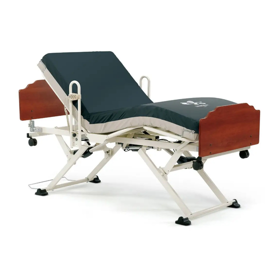
Invacare ®CS Series Beds
CS3, CS5, CS7, CS9, CS9FX600
User Manual
EN
Advertisement
Table of Contents

Related Manuals for Invacare CS3


Summary of Contents for Invacare CS3
-
Page 1: User Manual
Invacare ®CS Series Beds CS3, CS5, CS7, CS9, CS9FX600 User Manual For more information regarding bed rail safety, refer to the Bed Rail Entrapment Risk Notification Guide at www.invacare.com. This manual MUST be given to the user of the product. - Page 2 © 2011 Invacare Corporation. All rights reserved. Republication, duplication or modification in whole or in part is prohibited without prior written permission from Invacare. Trademarks are identified by ™ and ®. All trademarks are owned by or licensed to Invacare Corporation or its subsidiaries unless otherwise noted.
-
Page 3: Table Of Contents
USAGE Hand Control - Pendant Operation ........................................37 Pendant Storage and Location ..........................................39 Power Cord Storage .............................................41 Raise and Lower the Heel Lift Ratchet......................................42 Foot Pad Lock Mechanism on CS3 Bed......................................43 Bed Steer Mechanism............................................44 Part No 1153410 Invacare ®CS Series Beds... - Page 4 Optional 39 Inch and 42 Inch Wide Decks .....................................57 Adjustable Width Bed Model CS9FX600......................................58 MAINTENANCE Cleaning Instructions.............................................63 Annual Maintenance Check ..........................................64 Quarterly Maintenance Check..........................................64 Environmental Conditions for Storage and Transport .................................64 Environmental Conditions for Operation......................................64 10 TROUBLESHOOTING Invacare ®CS Series Beds Part No 1153410...
-
Page 5: General
Caution indicates a potentially hazardous situation which, if not avoided, may result in property damage or minor injury or both. IMPORTANT Indicates a hazardous situation that could result in damage to property if it is not avoided. Gives useful tips, recommendations and information for efficient, trouble-free use. Part No 1153410 Invacare ®CS Series Beds... - Page 6 1 GENERAL Symbols used on the CS Bed Battery Charging (Yellow) (on Trend ACP) Battery Fully Charged (Green) Invacare ®CS Series Beds Part No 1153410...
-
Page 7: Limited Warranty
MANUFACTURED AFTER JULY 4, 1975. This warranty is extended only to the original purchaser who purchases this product when new and unused from Invacare Continuing Care, Inc (ICCI) or a dealer. This warranty is not extended to any other person or entity and is not transferable or assignable to any subsequent purchaser or owner. Coverage under this warranty will end upon any such subsequent sale or other transfer of title to any other person. -
Page 8: Safety
Check all parts for shipping damage and test before using. In case of damage, DO NOT use. Contact ICCI Customer Service Department (1-800-668-2337)/Carrier for further instruction. This Manual/Electric bed has been engineered to provide reliable operation. The bed has been thoroughly tested and inspected prior to shipment. Invacare ®CS Series Beds Part No 1153410... -
Page 9: Operation Information
DO NOT entangle the cords on other objects. A pinched electric cord is dangerous and can become damaged. Use the Power Cord Strap when moving the bed. Refer to Pendant Storage and Location on page 39 and Power Cord Storage on page 41. Part No 1153410 Invacare ®CS Series Beds... - Page 10 This bed is rated to 600 lbs. (272 kg) for model CS9FX600, 500 lbs. (228 kg) for models CS5, CS7, and CS9 and 450 lbs. (204 kg) for model CS3. DO NOT overload the bed. The combined weight of patients, visitors, mattress, bedding and all accessories must NOT exceed rated capacity or Safe Working Load.
- Page 11 When using nasal or masked type oxygen administering equipment, the oxygen or air tubing MUST be routed and secured properly to ensure that the tubing does not become entangled and/or severed during normal operation of manual/electric bed. Part No 1153410 Invacare ®CS Series Beds...
- Page 12 Electric components, such as motors may cause severe injury including electrocution if exposed to water. During routine bed operation or when cleaning, DO NOT expose electrical components to water. Unplug and de- energize electrical components when water products are near these components. Invacare ®CS Series Beds Part No 1153410...
- Page 13 Given this situation, release the pendant button and allow the bed unit to sit for several minutes. This will allow the protection function time to reset and restore bed function. Depending on the severity of the initial overheating, this could take up to 30 minutes. Part No 1153410 Invacare ®CS Series Beds...
-
Page 14: Emi Information
Some cellular telephones and similar devices transmit signals while they are ON, even when not being used. Medium-range mobile transceivers, such as those used in police cars, fire trucks, ambulances and taxis. These usually have the antenna mounted on the outside of the vehicle; and Invacare ®CS Series Beds Part No 1153410... - Page 15 This product may contain substances that could be harmful to the environment if disposed of in places (landfills) that are not appropriate according to legislation. Please be environmentally responsible and recycle this product through your recycling facility at its end of life. Part No 1153410 Invacare ®CS Series Beds...
-
Page 16: Emc Information
Harmonic emissions IEC 61000-3-2 Class A Complies Voltage fluctuations / flicker emissions IEC 61000-3-3 Invacare ®CS Series Beds Part No 1153410... - Page 17 (30 % dip in U for 25 cycles for 25 cycles <5 % U <5 % U (>95 % dip in U (>95 % dip in U for 5 sec for 5 sec Part No 1153410 Invacare ®CS Series Beds...
- Page 18 CS Bed, including cables, than the recommended separation distance calculated from the equation applicable to the frequency of the transmitter. Recommended separation distance 3 Vrms 150 kHz to 80 Conducted RF d=1.2 IEC 61000-4-6 3 Vrms Invacare ®CS Series Beds Part No 1153410...
- Page 19 RF compliance level above, the CS Bed should be observed to verify normal operation. If abnormal performance is observed, additional measures may be necessary, such as re-orienting or relocating the CS Bed. Over the frequency range 150 kHz to 80 MHz, field strengths should be less than 3 V/m. Part No 1153410 Invacare ®CS Series Beds...
- Page 20 NOTE 1 At 80 MHz and 800 MHz, the separation distance for the higher frequency range applies. NOTE 2 These guidelines may not apply in all situations. Electromagnetic propagation is affected by absorption and reflection from structures, objects and people. Invacare ®CS Series Beds Part No 1153410...
-
Page 21: Product Labeling
éviter le coincement du patient. Il est important de lire et de comprendre le manuel de l'utilisateur avant understand the User Manual prior to using this equipment. ICCI manuals are available at www.invacare-cc.com or your d'utiliser cet équipement. Vous trouverez les manuels ICCI sur le site www.invacare-cc.com ou chez votre détaillant. - Page 22 4 PRODUCT LABELING Optional Foot End Board ACP with Trendelenburg Invacare ®CS Series Beds Part No 1153410...
-
Page 23: Technical Data
Typical Product Parameters Certifications All models (120 V~ models - CS3, CS5, CS7, CS9, CS9FX600 and 230 V~ models - CS7, CS9) conform to UL60601-1 and IEC60601-1. Certified to IEC60601-2-38 and IEC60601-1-2 and CAN/CSA C22.2 No. 601.1 Elevation Range (floor to deck) - Page 24 24 Volts DC and HI/LO) Six button hand pendant standard not available Eight button hand pendant with contour not available standard (10 button optional) function Attendant control panel (ACP) optional Trendelenburg ACP not available optional Invacare ®CS Series Beds Part No 1153410...
- Page 25 (standard with Trendelenburg 24V DC 9.2 Amps) Security - Pendant Lock-Out CS9FX600 Pendant connection from either side standard of bed ACL (attendant control lock-out) optional pendant HI/LO function lock-out Individual pendant function lock-out optional on ACP Part No 1153410 Invacare ®CS Series Beds...
- Page 26 35½ in (901 mm) 39 in Wide Deck 38½ in (978 mm) 42 in Wide Deck 41½ in (1054 mm) Width with assist rails - 36 in standard 39¼ in (997 mm) deck Invacare ®CS Series Beds Part No 1153410...
- Page 27 4 in bed length extension optional optional 39 in or 42 wide bed deck optional not available Not compatible with 68 inch rail. Adjustable Deck Standard Not Available Not compatible with 68 inch rail Part No 1153410 Invacare ®CS Series Beds...
-
Page 28: Mattress Specifications
Refer to the Bed Rail Entrapment Risk Notification Guide at www.invacare.com. Use only a mattress of recommended specifications with this bed. A mattress may not be included with this bed. It is highly recommended that you use an Invacare branded mattress that is designed to conform to the following dimensions:... -
Page 29: Set-Up
Steady upright bed. Slowly lower to floor - use two people if Slide off end boxes and remove plastic sleeve. necessary. Part No 1153410 Invacare ®CS Series Beds... - Page 30 Ensure the bed is lowered slowly to the floor. Use additional people, if necessary. Remove wood spacer from front end of bed by Cut the untrimmed or green tie holding the lifting it off of bed end brackets. head deck to the frame. Invacare ®CS Series Beds Part No 1153410...
- Page 31 Carefully cut the untrimmed or green tie holding 10. Carefully cut the untrimmed or green tie holding 11. Plug power cord into a properly grounded the pendant bundle. the mains cable bundle. outlet. Part No 1153410 Invacare ®CS Series Beds...
-
Page 32: Assembly Instructions
Keeper Rods prevent unsafe gaps from forming between the bed ends or rails and the mattress. Install the Mattress Keeping Rods correctly to prevent patient entrapment. The mattress keeper rods hold the mattress in place. Install them in the head and foot decks. Invacare ®CS Series Beds Part No 1153410... - Page 33 With the mattress keeper upright, insert the There are two choices for mattress keeper rod Mattress keeper rod insertion on 80 in Bed. rod ends into the appropriate deck holes. insertion. (76 in bed option shown above) Part No 1153410 Invacare ®CS Series Beds...
- Page 34 76 in Bed Only - Slide the bed end bracket in the 76 in Bed Only - Reinsert the bed end bracket bed end bracket. mounting channel. Align the hole in the bracket fasteners. with the channel hole. Invacare ®CS Series Beds Part No 1153410...
- Page 35 Head and foot ends are normally packaged together either in a cardboard box or on a wooden skid separate from the bed. Bed end model IHBEADJ must be used with bed model CS9FX600. Refer to Adjusting the Head Board Width for CS9FX600 on page 62. Part No 1153410 Invacare ®CS Series Beds...
- Page 36 The key is attached to the bed bracket with a Repeat on the other side, then the opposite bed bed cables (ACP cable and pendant coupling). lanyard. end, securing both mounting points on each Tighten the nut*. board. *ACP bed only. Invacare ®CS Series Beds Part No 1153410...
-
Page 37: Usage
7 Usage Hand Control - Pendant Operation CAUTION CRUSH Hazard. DO NOT place feet under the frame when lowering the bed. 3 Function Pendant Raise/Lower Head Raise/Lower Raise/Lower Knee FIGURE 1 3 Function Pendant Part No 1153410 Invacare ®CS Series Beds... - Page 38 7 USAGE 4 Function Pendant Alternate Pendants Raise/Lower Head Raise/Lower Knee Nurse Call Under the Bed Light Raise/Lower Raise/Lower Head and Knee FIGURE 2 4 Function Pendant Invacare ®CS Series Beds Part No 1153410...
-
Page 39: Pendant Storage And Location
20 times after main electrical power to the control box is cut. Ensure the hand pendant is not locked-out when discharging it. Place the pendant holster between the top Slide the pendant into the holster. Alternatively, use the pendant clip to rail bars. secure the pendant to bed linen. Part No 1153410 Invacare ®CS Series Beds... - Page 40 Screw the coupling cap to the threaded Y cap from the Y cable housing. Replace the end into the Y cable housing. cable housing end. cap on the other side of the bed. Invacare ®CS Series Beds Part No 1153410...
-
Page 41: Power Cord Storage
Secure the power cord to the back of the head end with the hook and loop strap when moving the bed. Excess power cord can be secured to the back of head end with the hook and loop strap. Part No 1153410 Invacare ®CS Series Beds... -
Page 42: Raise And Lower The Heel Lift Ratchet
To reset the ratchet mechanism, raise the At the lowest position the deck can once stop while being adjusted. platform to the highest level then lower the again be raised to the desired stop. platform in one motion. Invacare ®CS Series Beds Part No 1153410... -
Page 43: Foot Pad Lock Mechanism On Cs3 Bed
DO NOT move the bed unless the floor lock, caster lock, or foot pad is disengaged (unlocked). Mobility Stability Range Bed at the Lowest Position FIGURE 3 Foot Pad Lock Mechanism on CS3 Bed Part No 1153410 Invacare ®CS Series Beds... -
Page 44: Bed Steer Mechanism
Bed Steer Mechanism Steer mechanism is on either side of the With the locking wheel tab facing outward, When engaged the bed will steer easily. head end of the bed. flip the steer mechanism. Invacare ®CS Series Beds Part No 1153410... -
Page 45: Options
Safety Information For Options WARNING Refer to the Bed Rail Entrapment Risk Notification Guide at www.invacare.com. Patient ENTRAPMENT with Assist Rail or Assist Bar may cause injury or death. Mattress must fit snugly within the mattress keepers to prevent patient entrapment. Use only a mattress of recommended specifications with the bed. Monitor patient frequently. - Page 46 Entrapment, the mattress support platform should be left in the flat position while unattended (except when required otherwise by medical staff for special or particular circumstances). Use of incompatible trapeze units may cause injury and/or damage. Use only Invacare trapeze systems designed specially for the CS bed: Standard Trapeze (1153385) or Heavy Duty Trapeze (1153386).
- Page 47 Place the bed in the lowest position to minimize the risk from falls. The trapeze bar may damage walls and ceilings when used with the Trendelenburg feature. Invacare recommends removing the trapeze when using the Trendelenburg function.
-
Page 48: Bed Rails And Positioning Devices
The listed items are available as optional accessories: MODEL DESCRIPTION IHCSBEK 4 Inch Extension Kit IHCSDB Drainage Bag Holder IHCSTRP Standard Trapeze and Mounting Bracket IHCSTRPHD Heavy Duty Trapeze and Mounting Bracket IHCSPD Aftermarket Pan Deck Kit Invacare ®CS Series Beds Part No 1153410... -
Page 49: Optional Drainage Bag Holder
8 OPTIONS Optional Drainage Bag Holder Optional Touch-up Paint Sherwin-Williams ® 5A-58147 00(A) CODE 82X WHITE BIRCH 2nd Dimension 5.0 Acrylic Enamel This product can be purchased at Sherwin Williams Automotive paint branches only. Part No 1153410 Invacare ®CS Series Beds... -
Page 50: Optional Attendant Control Panel Operation
8 OPTIONS Optional Attendant Control Panel Operation 3 Function Pendant Attendant Control Panel Lockout FIGURE 1 3 Function Pendant Invacare ®CS Series Beds Part No 1153410... - Page 51 Coil any extra cable and secure to the bed. Test Nurse Call by pressing the red first aid button on the hand pendant. In the event of a power failure or an issue occurs within the electronic system of your Invacare bed, the nurse call button ...
- Page 52 8 OPTIONS The underbed light can be turned on by pressing the blue light button on the hand pendant. Press again to turn off. Attendant Alternate Pendants Control Panel Lockout All functionality is the same on the alternate pendants except where noted. Under the Bed Light Nurse Call FIGURE 2 4 Function Pendant Invacare ®CS Series Beds Part No 1153410...
-
Page 53: Optional Trendelenburg And Reverse Trendelenburg Attendant Control Panel
DO NOT install a CS Bed Extender on a bed that is equipped with the Trendelenburg and Reverse Trendelenburg feature. Under Nurse Bed Light Call FIGURE 3 Optional Trendelenburg and Reverse Trendelenburg Attendant Control Panel Part No 1153410 Invacare ®CS Series Beds... -
Page 54: Pendant Hi/Lo Lock Out - Optional
The head function and knee-foot function on the pendant remains operational whether the lock out is activated or deactivated. HI/LO Attendant Control Lockout Lockout (at foot end of the bed) FIGURE 4 Pendant HI/LO Lock Out - Optional Invacare ®CS Series Beds Part No 1153410... -
Page 55: Optional Cardiopulmonary Resuscitation (Cpr) Release
The clevis pin and retaining clip can be removed from the connection between the head actuator and head deck section to lower it. The head deck must be supported while removing the pin and lowering the head deck. Part No 1153410 Invacare ®CS Series Beds... - Page 56 A second person is recommended of bed ). the head deck. to gently lower the head deck. Foot end not shown for clarity. Rapid Action Once the CPR handle is squeezed, the head deck will drop rapidly. Invacare ®CS Series Beds Part No 1153410...
-
Page 57: Optional 39 Inch And 42 Inch Wide Decks
The CS bed is available with wider decks for resident comfort. Both 39 inch wide deck and 42 inch wide decks are factory installed options. 39 in or 42 in Nominal FIGURE 5 Optional 39 Inch and 42 Inch Wide Decks Part No 1153410 Invacare ®CS Series Beds... -
Page 58: Adjustable Width Bed Model Cs9Fx600
The CS9FX600 has eight adjustable deck wings which can be adjusted to 36 in, 39 in or 42 in. The locations of the wings and adjustment knobs are FIGURE 6 shown in Invacare ®CS Series Beds Part No 1153410... - Page 59 Adjustment Knob Adjustment Knob Adjustment Knob Adjustment Adjustment Knob Adjustment Knob Adjustment Knob Knobs Adjustable Head Section Adjustable Seat Adjustable Thigh Adjustable Foot Section Section Section FIGURE 6 Adjustable deck wings, knobs and snap buttons Part No 1153410 Invacare ®CS Series Beds...
- Page 60 Adjustable Hole Deck Deck Wing Hole Deck Wing Wing Adjustment Adjustment Adjustment Knob Knob Knob Snap Button Snap Button Snap Button Top Bed Deck View Top Bed Deck View Top Bed Deck View Invacare ®CS Series Beds Part No 1153410...
- Page 61 Adjust the head board width. Refer to Adjusting the Head Board Width for CS9FX600 on page 62. Repeat STEPS 1 to 6 for each section until they are all adjusted to the same width. Part No 1153410 Invacare ®CS Series Beds...
- Page 62 Move the board wing until the mounting holes line up with the desired adjustment holes in the center section. Install the knobs to secure the board wing in the desired position. Tighten securely Repeat STEPS 1-4 for the remaining board wing. Invacare ®CS Series Beds Part No 1153410...
-
Page 63: Maintenance
Rinse thoroughly with water (maximum temperature 110°F or 43°C). DO NOT use solvents, bleach, alcohol, petroleum products, caustic agents, or highly alkaline or acidic agents to clean the bed. Retract each actuator to the minimum stroke length before washing to avoid degreasing the piston rod. Dry all components before storing. Part No 1153410 Invacare ®CS Series Beds... -
Page 64: Annual Maintenance Check
Store and/or transport the bed in a clean and dry environment with an ambient temperature range between 10° and 50° Celsius (0° to 125° F). Environmental Conditions for Operation • Bring the bed to a Safe Operating Temperature between 5° and 40° Celsius (41° and 100° F) before operating the bed. Invacare ®CS Series Beds Part No 1153410... -
Page 65: Troubleshooting
Floor lock not functioning. Floor lock is stuck in one position. Contact Invacare Continuing Care Service Department 1-800-668-2337. Bed is not level Hi/Lo actuators are unevenly Bed deck is not parallel with floor... - Page 66 VERIFICATION CORRECTIVE ACTION Actuator not working. HI/LO lock-out is on. For non-openbus (CS3) - A Lockout Rotate the lockout dial to the “unlocked” position box (a square black box) with a (horizontal), or flip switch to OFF. toggle switch. When the switch is towards "ON"...
- Page 67 VERIFICATION CORRECTIVE ACTION Actuator not working. Faulty hand control pendant. Pendant cable is connected, power Contact Invacare Continuing Care Service is on, lock-out is off and hand Department 1-800-668-2337. control pendant does not function. Disconnect power supply then replace hand pendant with functioning unit (from another bed, if available).
- Page 68 Location: Invacare Continuing Care, Inc. 994 Hargrieve Road A subsidiary of Invacare Corporation. London, Ontario Canada For more information regarding Invacare continuing Care, N6E1P5 Inc. (ICCI) products, parts, and services, please visit www.invacare-cc.com or call 800-668-2337 Invacare Continuing Care, Inc.