Table of Contents
Advertisement
OM-2094
110100
Revised 01/01
Revised 02/01
Revised 03/01
Revised 05/01
Revised 06/01
Revised 07/01
Revised 08/01
Operation and Maintenance Manual
1.
Hobart Brothers Company (hereinafter called HOBART) warrants that each new and unused Hobart Ground
Power Equipment, (hereinafter called the PRODUCT) is of good workmanship and is free from mechanical defects,
Series 500285
Hobart Brothers Company
Ground Power Division
Troy, Ohio 45373
U.S.A.
Advertisement
Table of Contents
Troubleshooting

Related Manuals for Hobart Jet-Ex 5D


Summary of Contents for Hobart Jet-Ex 5D
- Page 1 Jet-Ex 5D Generator Sets Series 500285 Hobart Brothers Company Hobart Brothers Company (hereinafter called HOBART) warrants that each new and unused Hobart Ground Ground Power Division Power Equipment, (hereinafter called the PRODUCT) is of good workmanship and is free from mechanical defects, Troy, Ohio 45373 U.S.A.
-
Page 2: Section 1. Description
In the event any component manufacturer has warranted its component to HOBART and will not deal directly with a first user then HOBART will cooperate with the first user in the presentation of a claim to such manufacturer. Under NO circumstances does HOBART assume any liability for any warranty claim against or warranty work done by or in behalf of any manufacturer of the foregoing components. -
Page 3: General
OM-2094 / Operation and Maintenance Manual Jet-Ex 5D / Series 500285 / Generator Set Safety Warnings and Cautions WARNING CALIFORNIA PROPOSITION 65 - DIESEL ENGINES. Diesel engine exhaust and some of its constituents are known to the State of California to cause cancer, birth defects and other reproductive harm. - Page 4 OM-2094 / Operation and Maintenance Manual Jet-Ex 5D / Series 500285 / Generator Set Always connect the grounding lead, if supplied in a power line cable, to the grounded switch box or building ground. If not provided, use a separate grounding lead. Ensure that the current (amperage) capacity of the grounding lead will be adequate for the worst fault current situation.
- Page 5 OM-2094 / Operation and Maintenance Manual Jet-Ex 5D / Series 500285 / Generator Set Medical and First Aid Treatment First aid facilities and a qualified first aid person should be available for each shift for immediate treatment of all injury victims. Electric shock victims should be checked by a physician and taken to a hospital immediately if any abnormal signs are observed.
- Page 6 OM-2094 / Operation and Maintenance Manual Jet-Ex 5D / Series 500285 / Generator Set This page intentionally left blank. Safety Warnings November 1, 2000 Page 4 Revised 03/01...
- Page 7 These units are available as stationary, skid- mounted units, or they may be trailer-mounted for portability. Both versions are available with 14 V DC output capability. Most information in the manual applies to the 28.5 V Jet-Ex 5D in general. Information which applies to options and special equipment are listed in Appendix A.
- Page 8 A collection of manufacturer’s literature is supplied as part of the information package. If you have any questions concerning your Hobart Ground Power equipment, immediately contact our Service Department by mail, telephone or FAX. Write:...
-
Page 9: Table Of Contents
OM-2094 / Operation and Maintenance Manual Jet-Ex 5D / Series 500285 / Generator Set Table of Contents Chapter 1. Description/Operation Section 1. Description General Special Features Standard Options Orientation Identification Canopy Engine, Generator, and Controls General Engine Generator Rectifier Assembly... -
Page 10: Table Of Contents
OM-2094 / Operation and Maintenance Manual Jet-Ex 5D / Series 500285 / Generator Set Generator Operation Deliver Power Stop Operation (Shutdown) Adverse Weather Precautions Chapter 2. Servicing / Troubleshooting Section 1. Maintenance Inspection/Check General Maintenance Schedule General Maintenance Schedule Check Sheet... -
Page 11: Table Of Contents
OM-2094 / Operation and Maintenance Manual Jet-Ex 5D / Series 500285 / Generator Set Section 3. Adjustment/Test General Testing the Generator Set Pre-operational Test Procedures Operational Tests Voltage Regulator Adjustment 28.5 Volt Adjustment Line Drop Compensation Section 4. Troubleshooting Procedures... - Page 12 OM-2094 / Operation and Maintenance Manual Jet-Ex 5D / Series 500285 / Generator Set Explanation of Parts List Contents Parts List Form Section 2. Manufacturer’s Codes Explanation of Manufacturer’s (Vendor) Code List Section 3. Parts List Explanation of Parts List Arrangement Symbols and Abbreviations Section 4.
-
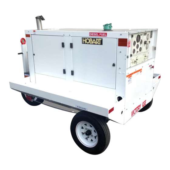
Page 13: Standard
Section 1. Description General The Jet-Ex 5D units (Figure 1) covered in this manual are diesel engine driven, self-contained generator sets manufactured by Hobart Brothers Company, Ground Power Division, Troy, Ohio U.S.A. A basic unit is identified by a Series Number - 500285 - plus a dash number which defines a specific configuration. - Page 14 OM-2094 / Operation and Maintenance Manual Jet-Ex 5D / Series 500285 / Generator Set Jet-Ex 5D Generator Set Figure 1 Chapter 1-1 November 1, 2000 Page 2 Revised 07/01...
- Page 15 OM-2094 / Operation and Maintenance Manual Jet-Ex 5D / Series 500285 / Generator Set Unit with Stationary Mount (500285-002) Length 68” (172.7 cm) Width 37” (94 cm) Height 46” (116.8 cm) Weight (dry fuel tank) 2400 lbs (1088.6 kg) Approx.
-
Page 16: Orientation
Jet-Ex 5D / Series 500285 / Generator Set Orientation The radiator end of the Jet-Ex 5D is the front. Right and left are determined by standing at the rear of the unit, facing it. The control panel is located at the rear. -
Page 17: Generator
OM-2094 / Operation and Maintenance Manual Jet-Ex 5D / Series 500285 / Generator Set 1. Fuel Tank Support 5. Generator 9. Battery 2. Fuel Tank 6. Frame 10. Contactor 3. Control Panel 7. Engine 4. Rectifier Assembly 8. Air Cleaner... - Page 18 OM-2094 / Operation and Maintenance Manual Jet-Ex 5D / Series 500285 / Generator Set 1. Muffler 2. Alternator 3. Oil filter 4. Starter 5. Starter solenoid Generator Set Components (Left Side) Figure 3 Chapter 1-1 November 1, 2000 Page 6...
- Page 19 OM-2094 / Operation and Maintenance Manual Jet-Ex 5D / Series 500285 / Generator Set 1. Fuel filter 2. Air cleaner 3. Throttle control assembly 4. Oil pressure sender 5. Oil pressure switch 20 psi (138 kPA) 6. Water Temp. Switch 7.
- Page 20 OM-2094 / Operation and Maintenance Manual Jet-Ex 5D / Series 500285 / Generator Set (2) Cooling fan The cooling fan on the engine is designed to blow air out through the radiator rather than to draw it in. This prevents hot air, heated by the engine, from entering the generator.
-
Page 21: Ammeter Shunt
OM-2094 / Operation and Maintenance Manual Jet-Ex 5D / Series 500285 / Generator Set c. Generator The generator (5, Figure 2) is a multi-phase, synchronous salient pole, revolving field, AC generator whose output is rectified. The output is rectified by a rectifier assembly (4) made up of twelve rectifiers connected into a full wave configuration. - Page 22 OM-2094 / Operation and Maintenance Manual Jet-Ex 5D / Series 500285 / Generator Set 1. TACHOMETER (M403) 11. ENGINE ON lamp (DS407) 2. HOUR METER (M402) 12. ENGINE START push button switch (S401) 3. VOLTMETER (generator) (M406) 13. ENGINE CIRCUIT toggle switch (S404) 4.
-
Page 23: Control Box Assembly (Front)
OM-2094 / Operation and Maintenance Manual Jet-Ex 5D / Series 500285 / Generator Set g. Control Box Assembly (Front) (Figure 5) The Control Box Assembly (Figure 5) houses and provides mounting facilities for controls, monitoring instruments, voltage regulator, relays, etc. The box is mounted at the rear of the canopy. - Page 24 OM-2094 / Operation and Maintenance Manual Jet-Ex 5D / Series 500285 / Generator Set This page intentionally left blank. Chapter 1-1 November 1, 2000 Page 12 Revised 07/01...
- Page 25 OM-2094 / Operation and Maintenance Manual Jet-Ex 5D / Series 500285 / Generator Set (12) ENGINE START push button switch (S401) The ENGINE START push button switch is a momentary contact switch which closes the starter solenoid (5, Figure 3) circuit and cranks the engine. This switch is operable only when the ENGINE CIRCUIT toggle switch (13, Figure 5) is held in its top spring-loaded START position.
- Page 26 OM-2094 / Operation and Maintenance Manual Jet-Ex 5D / Series 500285 / Generator Set 1. Over voltage relay (K403) 2. Voltage regulator (VR402) 3. Excitation rectifiers (CR417 & CR418) 4. Control windings fuses (10 Amp.) (F406 - F408) 5. Voltage build-up fuse (10 Amp.) (F405) 6.
- Page 27 In addition to the other devices provided by the engine manufacturer, an engine shutdown feature is added by Hobart Brothers. Since diesel engines typically require several minutes of running at idle speed before shutdown, this push button switch is intended for use in emergencies only.
- Page 28 OM-2094 / Operation and Maintenance Manual Jet-Ex 5D / Series 500285 / Generator Set This page intentionally left blank. Chapter 1-1 November 1, 2000 Page 16 Revised 07/01...
-
Page 29: Section 2. Preparation For Use, Storage Or Shipping
The oil level dipstick is located on the left side of the engine. Refer to the Engine Manufactures User’s handbook for oil recommendations. c. Output Cable Requirements and Installation Jet-Ex 5D units are normally supplied with a 30ft. generator-to-aircraft output cable. This output cable consists of two single conductor 4/0 cables. (1) Cable requirements ·... - Page 30 OM-2094 / Operation and Maintenance Manual Jet-Ex 5D / Series 500285 / Generator Set · The recommended cable size for 28.5 volt DC is determined by the maximum starting load amperage expectations. A maximum starting load of 1500 amps. requires two single conductor 4/0 cables.
-
Page 31: Preparation For Storage
Long Time Storage (1) Engine Protection The Jet-Ex 5D generator set may be stored for long periods if the engine is given proper protection from rust and corrosion. Refer to the Engine Manufactures Users Handbook for proper procedures to be followed. - Page 32 OM-2094 / Operation and Maintenance Manual Jet-Ex 5D / Series 500285 / Generator Set This page intentionally left blank. Chapter 1-2 November 1, 2000 Page 4...
-
Page 33: Operating The Generator Set
OM-2094 / Operation and Maintenance Manual Jet-Ex 5D / Series 500285 / Generator Set Section 3. Operation General This section contains information and instructions for the safe and efficient operation of the generator set. Operating instructions are presented in a step-by-step sequence of procedures to be followed in supplying power to an aircraft. - Page 34 OM-2094 / Operation and Maintenance Manual Jet-Ex 5D / Series 500285 / Generator Set 1. TACHOMETER M403 11. ENGINE ON lamp DS407 2. HOUR METER M402 12. ENGINE START push button switch S401 3. VOLTMETER (generator) M406 13. ENGINE CIRCUIT toggle switch S404 4.
-
Page 35: Starting The Engine
OM-2094 / Operation and Maintenance Manual Jet-Ex 5D / Series 500285 / Generator Set c. Starting The Engine (Figure 1) Make sure that all Prestarting Instructions have been carried out, and reference to Initial Preparation for Use has been checked for operating details. -
Page 36: Adverse Weather Precautions
OM-2094 / Operation and Maintenance Manual Jet-Ex 5D / Series 500285 / Generator Set CAUTION THE BATTERY WILL DRAIN if the ENGINE CIRCUIT toggle switch (13), is not placed in STOP position after shutdown, (2) Emergency Conditions To prevent personal damage or damage to generator set, use of the EMERGENCY SHUT DOWN (E-STOP) push button switch will provide immediate shut down of the engine. - Page 37 OM-2094 / Operation and Maintenance Manual Jet-Ex 5D / Series 500285 / Generator Set (2) Operation in Hot and Humid Conditions a. Cooling system Maintain a more frequent check of the coolant level in the radiator. (3) Operation in Extremely Dusty Conditions If unit is to be operated under dusty, out-of-door conditions, place it in a sheltered area.
- Page 38 OM-2094 / Operation and Maintenance Manual Jet-Ex 5D / Series 500285 / Generator Set This page intentionally left blank. Chapter 1-3 November 1, 2000 Page 6...
-
Page 39: Section 1. Maintenance Inspection/Check
OM-2094 / Operation and Maintenance Manual Jet-Ex 5D / Series 500285 / Generator Set Chapter 2. Servicing / Troubleshooting Section 1. Maintenance Inspection/Check General To make certain that generator set is always in good operating condition, it must be inspected, maintained, and lubricated regularly and systematically. - Page 40 OM-2094 / Operation and Maintenance Manual Jet-Ex 5D / Series 500285 / Generator Set 8 hrs. First 500 hrs. Daily 250 hrs. Service 2000 Recommended Service Intervals Hours 6 Months 20/40 Months Engine Check oil level Check coolant level Check fuel quantity...
-
Page 41: Inspection And Cleaning
OM-2094 / Operation and Maintenance Manual Jet-Ex 5D / Series 500285 / Generator Set Inspection and Cleaning Every day, check for oil, coolant, or fuel leaks. Also check for loose electrical connection. Check oil pressure with engine running at rated RPM (2500). Do not operate engine if oil pressure is less than 20 psi (138 kPA). - Page 42 OM-2094 / Operation and Maintenance Manual Jet-Ex 5D / Series 500285 / Generator Set This page intentionally left blank Chapter 2-1 November 1, 2000 Page 4 Revised 03/01...
-
Page 43: Section 2. Maintenance Procedures
OM-2094 / Operation and Maintenance Manual Jet-Ex 5D / Series 500285/ Generator Set Section 2. Maintenance Procedures General A suggested Maintenance Schedule is provided in Section 1 of this Chapter. Each step of the schedule is also covered in general in Section 1. This Section covers maintenance in more detail where necessary. - Page 44 OM-2094 / Operation and Maintenance Manual Jet-Ex 5D / Spec. 7500285/ Generator Set Check oil daily Check crankcase oil daily; change 200 hours. Change oil filter after 200 hours. Lubrication Chart Figure 1 Chapter 2-2 November 1, 2000 Page 2...
- Page 45 OM-2094 / Operation and Maintenance Manual Jet-Ex 5D / Series 500285/ Generator Set Symbol Name Specification Notes Grease, Automotive and Federal VV-G-632 Sinclair LItholene Industrial Industrial No.2; Mobile-Mobilplex 47 or equivalent. Oil, Engine, Heavy Duty MIL-L-46152 or See Cummins Engine MIL-L-2104C User’s Handbook for...
-
Page 46: Servicing The Air Cleaner
OM-2094 / Operation and Maintenance Manual Jet-Ex 5D / Spec. 7500285/ Generator Set h. Remove filler cap on valve cover and refill crankcase with fresh clean oil, of proper specification and viscosity (see Para. 2, E, (2) and Figure 2). Seven quarts are required when oil filter is changed. -
Page 47: Radiator Cap Removal
OM-2094 / Operation and Maintenance Manual Jet-Ex 5D / Series 500285/ Generator Set a. Radiator Cap Removal Cover the cap with a thick cloth and turn it slowly counterclockwise to the first stop. When pressure is completely released, press downward and finish removing cap. -
Page 48: Cleaning The Battery
OM-2094 / Operation and Maintenance Manual Jet-Ex 5D / Spec. 7500285/ Generator Set mix the water and the electrolyte, or damage to the battery will result from the water freezing. e. Cleaning the Battery If the top of the battery is dirty, it may be cleaned with a brush dipped in ammonia or soda solution. -
Page 49: Generator Maintenance
OM-2094 / Operation and Maintenance Manual Jet-Ex 5D / Series 500285/ Generator Set Generator Maintenance a. General The only maintenance service required for the generator will be brush replacement, slip ring cleaning, etc. b. Brush Service If inspection reveals that brushes are gummy or sticking in the brush holders, they should be removed and cleaned. - Page 50 OM-2094 / Operation and Maintenance Manual Jet-Ex 5D / Spec. 7500285/ Generator Set This page intentionally left blank. Chapter 2-2 November 1, 2000 Page 8 Revised 08/01...
-
Page 51: Section 3. Adjustment/Test
OM-2094 / Operation and Maintenance Manual Jet-Ex 5D / Series 500285 / Generator Set Section 3. Adjustment/Test General The adjustments and test procedures presented below are required after major repairs, parts replacement, or long storage. Testing the Generator Set Test values listed below will result when the generator set is operating properly. If your test results are not within the limits shown, perform the applicable troubleshooting procedures given in Chapter 3. - Page 52 OM-2094 / Operation and Maintenance Manual Jet-Ex 5D / Series 500285 / Generator Set 1. TACHOMETER M403 11. ENGINE ON lamp DS407 2. HOUR METER M402 12. ENGINE START push button switch S401 3. VOLTMETER (generator) M406 13. ENGINE CIRCUIT toggle switch S404 4.
-
Page 53: Operational Tests
OM-2094 / Operation and Maintenance Manual Jet-Ex 5D / Series 500285 / Generator Set b. Operational Tests (Figure 1) (1) Start the engine as described in 1-3; Para. 2, and let it warm at idle speed. (2) Inspect for oil, fuel, and coolant leaks. -
Page 54: Voltage Regulator Adjustment
OM-2094 / Operation and Maintenance Manual Jet-Ex 5D / Series 500285 / Generator Set Voltage Regulator Adjustment a. 28.5 Volt Adjustment (1) The regulating voltage, in the 28.5 volt range, is determined by the position of the wiper arm of the multi-turn potentiometer (1,Figure 2) R46. -
Page 55: Section 4. Troubleshooting Procedures
OM-2094 / Operation and Maintenance Manual Jet-Ex 5D / Series 500285 / Generator Set Section 4. Troubleshooting Procedures General Troubleshooting is an orderly process of checking and eliminating possible causes of trouble until the exact cause of a trouble is found. As a rule, the best place to start looking for the cause of a trouble in a circuit is at the source of power. - Page 56 OM-2094 / Operation and Maintenance Manual Jet-Ex 5D / Series 500285 / Generator Set 1. Fuel Tank Support 6. Frame 2. Fuel Tank 7. Engine 3. Control Panel 8. Air Cleaner 4. Rectifier Assembly 9. Battery 5. Generator 10. Contactor...
- Page 57 OM-2094 / Operation and Maintenance Manual Jet-Ex 5D / Series 500285 / Generator Set 1. Muffler 2. Alternator 3. Oil filter 4. Starter 5. Starter solenoid Engine Comp[onents (Right Side of Unit) Figure 2 November 1, 2000 Chapter 2-4 Revised 07/01...
- Page 58 OM-2094 / Operation and Maintenance Manual Jet-Ex 5D / Series 500285 / Generator Set 1. Fuel filter 2. Air cleaner 3. Throttle control assembly 4. Oil pressure sender 5. Oil pressure switch 20 psi (138 kPA) 6. Water Temp. Sender 7.
- Page 59 OM-2094 / Operation and Maintenance Manual Jet-Ex 5D / Series 500285 / Generator Set 1. TACHOMETER (M403) 11. ENGINE ON lamp (DS407) 2. HOUR METER (M402) 12. ENGINE START push button switch (S401) 3. VOLTMETER (generator) (M406) 13. ENGINE CIRCUIT toggle switch (S404) 4.
- Page 60 OM-2094 / Operation and Maintenance Manual Jet-Ex 5D / Series 500285 / Generator Set 1. Over voltage relay (K403) 2. Voltage regulator (VR402) 3. Excitation rectifiers (CR417 & CR418) 4. Control windings fuses (10 Amp.) (F406 - F408) 5. Voltage build-up fuse (10 Amp.) (F405) 6.
-
Page 61: Section 5. Troubleshooting Charts
OM-2094 / Operation and Maintenance Manual Jet-Ex 5D / Series 500285 / Generator Set Section 5. Troubleshooting Charts See section 2-4 for all figures referenced in this section. Engine and Controls Trouble, Symptom and Condition Probable Cause Test, Check, and Remedy 1. - Page 62 OM-2094 / Operation and Maintenance Manual Jet-Ex 5D / Series 500285 / Generator Set Engine and Controls (continued) See section 2-4 for all figures referenced in this section. Trouble, Symptom and Condition Probable Cause Test, Check, and Remedy Engine will not start. Starter f.
- Page 63 OM-2094 / Operation and Maintenance Manual Jet-Ex 5D / Series 500285 / Generator Set Engine and Controls (continued) See section 2-4 for all figures referenced in this section. Trouble, Symptom and Condition Probable Cause Test, Check, and Remedy 4. Engine starts then stops when a.
- Page 64 OM-2094 / Operation and Maintenance Manual Jet-Ex 5D / Series 500285 / Generator Set Engine and Controls (continued) See section 2-4 for all figures referenced in this section. Trouble, Symptom and Condition Probable Cause Test, Check, and Remedy 7. Engine lacks power.
- Page 65 OM-2094 / Operation and Maintenance Manual Jet-Ex 5D / Series 500285 / Generator Set Generator and Controls See section 2-4 for all figures referenced in this section. Trouble, Symptom and Condition Probable Cause Test, Check, and Remedy 1. Generator will not build up a.
- Page 66 OM-2094 / Operation and Maintenance Manual Jet-Ex 5D / Series 500285 / Generator Set Generator and Controls (continued) See section 2-4 for all figures referenced in this section. Trouble, Symptom and Condition Probable Cause Test, Check, and Remedy Generator will not build up h.
- Page 67 OM-2094 / Operation and Maintenance Manual Jet-Ex 5D / Series 500285 / Generator Set Generator and Controls (continued) See section 2-4 for all figures referenced in this section. Trouble, Symptom and Condition Probable Cause Test, Check, and Remedy Load contactor will not close c.
- Page 68 OM-2094 / Operation and Maintenance Manual Jet-Ex 5D / Series 500285 / Generator Set Generator and Controls (continued) See section 2-4 for all figures referenced in this section. Trouble, Symptom and Condition Probable Cause Test, Check, and Remedy 7. Output current cannot be a.
- Page 69 Figure 1 shows a rear view and side view of the flexible coupling assembly. The primary function of this assembly is to couple a Hobart generator set to a diesel engine. The flexible coupling assembly compensates for slight misalignment between the engine and the generator, due to manufacturing tolerances.
-
Page 70: Coupling Screws (Routine Coupling Maintenance)
Use a long-handled, reversible ratchet drive fitted with a 5/16-inch Allen wrench to remove one coupling screw. Examine the screw. Screws specified for this coupling are Hobart Part No. 402789-004, which are socket-head, 3/8 - 16 X 3/4 inch long. -
Page 71: Disassembly
Check the flexible coupling disks for warping, cracks, or worn mounting holes. d. Check the screws which attach the flexible disks to the hub. The screws are Hobart Part No. 287935-001, which are socket head, 3/8 - 16 X 2-1/4 inch long. If they are cracked, stretched, or have stripped threads, replace them. -
Page 72: Coupling Service
If you have any questions concerning your Hobart Ground Power equipment, immediately contact our Service Department by mail, telephone or FAX. When calling about service or parts from your Hobart Brothers Company Distributor, be sure to include all pertinent information from the unit’s identification plate: Specification No., Model No., and unit rating. -
Page 73: Cleaning
(1) Attach the four flexible disks to the coupling hub with the six socket head 3/8 - 16 X 2-1/4 inch screws (Hobart Part No. 287935-001). The screws must be torqued to 40 - 45 foot-pounds (54 - 61 Nm). - Page 74 OM-2094 / Operation and Maintenance Manual Jet-Ex 5D / Series 500285/ Generator Set (12) Refer to Figure 2. Insert and hold a short iron bar through the flywheel housing against the fan blades of the fan and coupling assembly to block the armature against clockwise rotation. Do this carefully to avoid damaging the fan blades.
-
Page 75: Run-In And Periodic Check
OM-2094 / Operation and Maintenance Manual Jet-Ex 5D / Series 500285/ Generator Set Run-in and Periodic Check a. Mount the engine-generator assembly in a suitable test area and operate it for a 2-hour run-in. b. Shut down the engine after 2 hours and re-torque all coupling screws to 40 - 45 foot-pounds (54 - 61 Nm) to compensate for normal torque relaxation. - Page 76 OM-2094 / Operation and Maintenance Manual Jet-Ex 5D / Series 500285/ Generator Set This page intentionally left blank. Chapter 3-1 November 1, 2000 Page 8 Revised 03/01...
-
Page 77: Section 1. Introduction
Section 1. Introduction General The illustrated Parts List identifies, describes, and illustrates main assemblies, sub-assemblies, and detail parts of the Jet-Ex 5D Generator Sets manufactured by Hobart Brothers Company, Ground Power Division, Troy, Ohio 45373. Purpose The purpose of this list is to provide parts identification and descriptive information to maintenance and provisioning personnel for use in provisioning, requisitioning, purchasing, storing, and issuing of spare parts. - Page 78 Jet-Ex 5D / Series 500285/ Generator Set (2) “HOBART PART NUMBER” Column ALL part numbers appearing in this column are Hobart numbers. In all instances where the part is a purchased item, the vendor’s identifying five-digit code and his part number will appear in the “Nomenclature”...
-
Page 79: Explanation Of Manufacturer's (Vendor) Code List
OM-2094 / Operation and Maintenance Manual Jet-Ex 5D / Series 500285/ Generator Set Section 2. Manufacturer’s Codes Explanation of Manufacturer’s (Vendor) Code List The following list is a compilation of vendor codes with names and addresses for suppliers of purchased parts listed in this publication. The codes are in accordance with the Federal Supply Codes for Manufacturer’s Cataloging Handbook H4-l, and are arranged in numerical order. - Page 80 OM-2094 / Operation and Maintenance Manual Jet-Ex 5D / Series 500285 / Generator Set Code Vendor’s Name and Address 5E599 NVF Co., Primary Products Div., Yorklyn Rd, Yorklyn DE 19736 57733 Stewart-Warner Corp., 1826 Diversey Parkway, Chicago, IL 60614 59993 International Rectifier, 233 Kansas St., EL Segundo CA 90245...
-
Page 81: Explanation Of Parts List Arrangement
OM-2094 / Operation and Maintenance Manual Jet-Ex 5D / Series 500285 / Generator Set Section 3. Parts List Explanation of Parts List Arrangement The parts list is arranged so that the illustration will appear on a left-hand page and the applicable parts list will appear on the opposite right-hand page. - Page 82 OM-2094 / Operation and Maintenance Manual Jet-Ex 5D / Series 500285/ Generator Set Generator Set Assembly Figure 1 Chapter 4-3 November 1, 2000 Page 2 Revised 06/01...
- Page 83 OM-2094 / Operation and Maintenance Manual Jet-Ex 5D / Series 500285 / Generator Set NOMENCLATURE FIGURE & HOBART AIRLINE ITEM NO. PART NO. PART NO. 1 2 3 4 5 6 7 EFF QTY 500285-001 GENERATOR SET ASSEMBLY WITH TRAILER AND CABLE TRAYS...
- Page 84 OM-2094 / Operation and Maintenance Manual Jet-Ex 5D / Series 500285/ Generator Set Mounting Frame Assembly Figure 2 Chapter 4-3 November 1, 2000 Page 4 Revised 06/01...
- Page 85 OM-2094 / Operation and Maintenance Manual Jet-Ex 5D / Series 500285 / Generator Set NOMENCLATURE FIGURE & HOBART AIRLINE ITEM NO. PART NO. PART NO. 1 2 3 4 5 6 7 EFF QTY No Number MOUNTING FRAME ASSEMBLY 2- 1 287971 .
- Page 86 OM-2094 / Operation and Maintenance Manual Jet-Ex 5D / Series 500285/ Generator Set Canopy Components Figure 3 Chapter 4-3 November 1, 2000 Page 6 Revised 06/01...
- Page 87 OM-2094 / Operation and Maintenance Manual Jet-Ex 5D / Series 500285 / Generator Set NOMENCLATURE FIGURE & HOBART AIRLINE ITEM NO. PART NO. PART NO. 1 2 3 4 5 6 7 EFF QTY No Number CANOPY COMPONENTS 3- 1 287981 .
- Page 88 OM-2094 / Operation and Maintenance Manual Jet-Ex 5D / Series 500285/ Generator Set Generator Interior Components Figure 4 Chapter 4-3 November 1, 2000 Page 8 Revised 06/01...
- Page 89 OM-2094 / Operation and Maintenance Manual Jet-Ex 5D / Series 500285 / Generator Set NOMENCLATURE FIGURE & HOBART AIRLINE ITEM NO. PART NO. PART NO. 1 2 3 4 5 6 7 EFF QTY No Number GENERATOR SET INTERIOR COMPONENTS...
- Page 90 OM-2094 / Operation and Maintenance Manual Jet-Ex 5D / Series 500285/ Generator Set Control Box Assembly Figure 5 Chapter 4-3 November 1, 2000 Page 10 Revised 06/01...
- Page 91 OM-2094 / Operation and Maintenance Manual Jet-Ex 5D / Series 500285 / Generator Set NOMENCLATURE FIGURE & HOBART AIRLINE ITEM NO. PART NO. PART NO. 1 2 3 4 5 6 7 EFF QTY 288007-001 CONTROL PANEL ASSY 5- 1 286865 .
- Page 92 OM-2094 / Operation and Maintenance Manual Jet-Ex 5D / Series 500285/ Generator Set This page intentionally left blank. Chapter 4-3 November 1, 2000 Page 12 Revised 06/01...
- Page 93 OM-2094 / Operation and Maintenance Manual Jet-Ex 5D / Series 500285 / Generator Set NOMENCLATURE FIGURE & HOBART AIRLINE ITEM NO. PART NO. PART NO. 1 2 3 4 5 6 7 EFF QTY 288007-001 CONTROL BOX ASSY (continued) 5-34 404065-002 .
- Page 94 OM-2094 / Operation and Maintenance Manual Jet-Ex 5D / Series 500285/ Generator Set Battery Components Figure 6 Chapter 4-3 November 1, 2000 Page 14 Revised 06/01...
- Page 95 OM-2094 / Operation and Maintenance Manual Jet-Ex 5D / Series 500285 / Generator Set NOMENCLATURE FIGURE & HOBART AIRLINE ITEM NO. PART NO. PART NO. 1 2 3 4 5 6 7 EFF QTY No Number BATTERY COMPONENTS 6- 1 281881-001 .
- Page 96 OM-2094 / Operation and Maintenance Manual Jet-Ex 5D / Series 500285/ Generator Set Muffler Components Figure 7 Chapter 4-3 November 1, 2000 Page 16 Revised 06/01...
- Page 97 OM-2094 / Operation and Maintenance Manual Jet-Ex 5D / Series 500285 / Generator Set NOMENCLATURE FIGURE & HOBART AIRLINE ITEM NO. PART NO. PART NO. 1 2 3 4 5 6 7 EFF QTY No Number MUFFLER AND AIR CLEANER COMPONENTS...
- Page 98 OM-2094 / Operation and Maintenance Manual Jet-Ex 5D / Series 500285/ Generator Set Rectifier Assembly Figure 8 Chapter 4-3 November 1, 2000 Page 18 Revised 06/01...
- Page 99 OM-2094 / Operation and Maintenance Manual Jet-Ex 5D / Series 500285 / Generator Set NOMENCLATURE FIGURE & HOBART AIRLINE ITEM NO. PART NO. PART NO. 1 2 3 4 5 6 7 EFF QTY 288306 RECTIFIER ASSEMBLY 8 - 1 287184-003 .
- Page 100 OM-2094 / Operation and Maintenance Manual Jet-Ex 5D / Series 500285/ Generator Set Contactor Components Figure 9 Chapter 4-3 November 1, 2000 Page 20 Revised 06/01...
- Page 101 OM-2094 / Operation and Maintenance Manual Jet-Ex 5D / Series 500285 / Generator Set NOMENCLATURE FIGURE & HOBART AIRLINE ITEM NO. PART NO. PART NO. 1 2 3 4 5 6 7 EFF QTY No Number CONTACTOR COMPONENTS 9 - 1 .
- Page 102 OM-2094 / Operation and Maintenance Manual Jet-Ex 5D / Series 500285/ Generator Set Engine Components Figure 10 Chapter 4-3 November 1, 2000 Page 22 Revised 06/01...
- Page 103 OM-2094 / Operation and Maintenance Manual Jet-Ex 5D / Series 500285 / Generator Set NOMENCLATURE FIGURE & HOBART AIRLINE ITEM NO. PART NO. PART NO. 1 2 3 4 5 6 7 EFF QTY No Number ENGINE COMPONENTS 10- 1 W9360-229 .
- Page 104 OM-2094 / Operation and Maintenance Manual Jet-Ex 5D / Series 500285/ Generator Set Cooling System Components Figure 11 Chapter 4-3 November 1, 2000 Page 24 Revised 06/01...
- Page 105 OM-2094 / Operation and Maintenance Manual Jet-Ex 5D / Series 500285 / Generator Set NOMENCLATURE FIGURE & HOBART AIRLINE ITEM NO. PART NO. PART NO. 1 2 3 4 5 6 7 EFF QTY No Number COOLING SYSTEM COMPONENTS 11-1 056534 .
- Page 106 OM-2094 / Operation and Maintenance Manual Jet-Ex 5D / Series 500285/ Generator Set Fuel System Components Figure 12 Chapter 4-3 November 1, 2000 Page 26 Revised 06/01...
- Page 107 OM-2094 / Operation and Maintenance Manual Jet-Ex 5D / Series 500285 / Generator Set NOMENCLATURE FIGURE & HOBART AIRLINE ITEM NO. PART NO. PART NO. 1 2 3 4 5 6 7 EFF QTY No Number FUEL SYSTEM COMPONENTS 12-1 288009 .
- Page 108 OM-2094 / Operation and Maintenance Manual Jet-Ex 5D / Series 500285/ Generator Set Generator Assembly Figure 13 Chapter 4-3 November 1, 2000 Page 28 Revised 06/01...
- Page 109 OM-2094 / Operation and Maintenance Manual Jet-Ex 5D / Series 500285 / Generator Set NOMENCLATURE FIGURE & HOBART AIRLINE ITEM NO. PART NO. PART NO. 1 2 3 4 5 6 7 EFF QTY 287556 GENERATOR, ASSY. 288210 SPARE GENERATOR ASSEMBLY...
- Page 110 OM-2094 / Operation and Maintenance Manual Jet-Ex 5D / Series 500285/ Generator Set Brushholder Assembly Figure 14 Chapter 4-3 November 1, 2000 Page 30 Revised 06/01...
- Page 111 OM-2094 / Operation and Maintenance Manual Jet-Ex 5D / Series 500285 / Generator Set NOMENCLATURE FIGURE & HOBART AIRLINE ITEM NO. PART NO. PART NO. 1 2 3 4 5 6 7 EFF QTY 14 - 488784 BRUSH HOLDER ASSEMBLY...
- Page 112 OM-2094 / Operation and Maintenance Manual Jet-Ex 5D / Series 500285/ Generator Set Air Cleaner Components Figure 15 Chapter 4-3 November 1, 2000 Page 32 Revised 06/01...
- Page 113 OM-2094 / Operation and Maintenance Manual Jet-Ex 5D / Series 500285 / Generator Set NOMENCLATURE FIGURE & HOBART AIRLINE ITEM NO. PART NO. PART NO. 1 2 3 4 5 6 7 EFF QTY 15 - No Number AIR CLEANER COMPONENTS...
- Page 114 OM-2094 / Operation and Maintenance Manual Jet-Ex 5D / Series 500285/ Generator Set Trailer Components Figure 16 Chapter 4-3 November 1, 2000 Page 34 Revised 06/01...
- Page 115 OM-2094 / Operation and Maintenance Manual Jet-Ex 5D / Series 500285 / Generator Set NOMENCLATURE UNITS FIGURE HOBART ITEM NO. PART NO. 1234567 EFF ASSY No Number TRAILER W/FENDERS & CABLE TRAYS 16-1 181256 . KNOB, BRAKE LEVER * 16-2 287565 .
- Page 116 OM-2094 / Operation and Maintenance Manual Jet-Ex 5D / Series 500285/ Generator Set This page intentionally left blank. Chapter 4-3 November 1, 2000 Page 36 Revised 05/01...
- Page 117 OM-2094 / Operation and Maintenance Manual Jet-Ex 5D / Series 500285 / Generator Set NOMENCLATURE UNITS FIGURE HOBART ITEM NO. PART NO. 1234567 EFF ASSY No Number TRAILER W/FENDERS & CABLE TRAYS (cont) A 16-42 85A-1023 ..SEAL, GREASE, V22938, NO. 6300...
- Page 118 OM-2094 / Operation and Maintenance Manual Jet-Ex 5D / Series 500285/ Generator Set This page intentionally left blank. Chapter 4-3 November 1, 2000 Page 38 Revised 06/01...
- Page 119 OM-2094 / Operation and Maintenance Manual Jet-Ex 5D / Series 500285 / Generator Set Section 4. Numerical Index 1. Explanation of Numerical Index The purpose of this index is to assist the user in finding the illustration and description of a part when the part number is known.
- Page 120 OM-2094 / Operation and Maintenance Manual Jet-Ex 5D / Series 500285 / Generator Set FIG-ITEM PART FIG-ITEM PART NUMBER NUMBER 287556 10- 3 288014 13- 2 287564 8 -29 288015 16-2 287565 5-38 288016 5-42 287621 5-41 288017 12-2 287639...
- Page 121 OM-2094 / Operation and Maintenance Manual Jet-Ex 5D / Series 500285 / Generator Set FIG-ITEM PART FIG-ITEM PART NUMBER NUMBER 5-29 400642-003 9 - 8 489658-010 16-23 400954 4-11 489689 5-19 401428-001 5- 4 494134-001 16-25 401468 6- 5 494295...
- Page 122 OM-2094 / Operation and Maintenance Manual Jet-Ex 5D / Series 500285 / Generator Set FIG-ITEM PART FIG-ITEM PART NUMBER NUMBER 8 -17 W11097-007 5-35 W10051-010 8 -21 W11097-022 5-23 W10051-014 8 - 9 W11114-012 13-14 W10072-063 5- 2 W11166-001 10-14...
- Page 123 Jet-Ex 5D / Series 500285 / Generator Set Chapter 5. Manufacturer’s Literature Section 1. Manufacturer’s Listing VENDOR LITERATURE Engine Cummins Engine Operation Manual Cummins Engine Parts Catalog Hobart Brothers Diagrams: 288005 - Connection and Schematic Diagram, Jet-Ex 5D, Series 500285 November 1, 2000 Chapter 5-1 Page 1...
- Page 124 OM-2094 / Operation and Maintenance Manual Jet-Ex 5D / Series 500285 / Generator Set This page intentionally left blank Chapter 5-1 November 1, 2000 Page 2...
- Page 133 OM-2094 / Operation and Maintenance Manual Jet-Ex 5D / Series 500285 / Generator Set Appendix A. Options/Features The following is a list of options available for Series 500285. This chart contains the description, part number, and document number of the option. There is also a column to identify which option is contained in this Appendix.
- Page 134 OM-2094 / Operation and Maintenance Manual Jet-Ex 5D / Series 500285 / Generator Set This page intentionally left blank Appendix A November 1, 2000 Page 2...
- Page 135 OM-2094 / Operation and Maintenance Manual Jet-Ex 5D / Series 500285 / Generator Set Unusual Service Conditions This information is a general guideline and cannot cover all possible conditions of equipment use. The specific local environments may be dependent upon conditions beyond the manufacturer’s control. The manufacturer should be consulted if any unusual conditions of use exist which may affect the physical condition or operation of the equipment.
- Page 136 OM-2094 / Operation and Maintenance Manual Jet-Ex 5D / Series 500285 / Generator Set This page intentionally left blank Unusual Service Conditions November 1, 2000 Page 2...
- Page 137 OM-2094 / Operation and Maintenance Manual Jet-Ex 5D / Series 500285 / Generator Set Wet-Stacking in Generator Set Diesel Engines All diesel engines operated for extended periods under light load may develop a condition commonly referred to as wet-stacking. This condition results from the accumulation of unburned fuel in the exhaust system.
- Page 138 OM-2094 / Operation and Maintenance Manual Jet-Ex 5D / Series 500285 / Generator Set This page intentionally left blank. Wet Stacking November 1, 2000 Page 2...