
Related Manuals for Agilent Technologies NPD


Summary of Contents for Agilent Technologies NPD
- Page 1 Installation Guide Nitrogen-Phosphorus Detector on 6890 GC Accessories G1575A, G1576A, G1594A, G1599A...
- Page 2 Safety Information CAUTION A caution calls attention to a condition or All Rights Reserved. Reproduction, The Agilent Technologies 6890 Gas possible situation that could damage or adaptation, or translation without Chromatograph meets the following IEC destroy the product or the user’s work.
-
Page 3: Parts List
Overview Overview This section reviews the procedure for installing a nitrogen-phosphorus detector (NPD) on an Agilent 6890 Gas Chromatograph (hereafter referred to as the GC.) Before following this procedure, refer to the safety information on the inside back cover. Parts List •... - Page 4 Installing the flow manifold Installing the makeup gas regulator (nonEPC detectors only) Positioning and securing the detector Connecting the detector Routing the tubing Installing the nutwarmer cup (adaptable NPD only) Restoring the GC to operating condition Calibrating your detector (EPC detectors only)
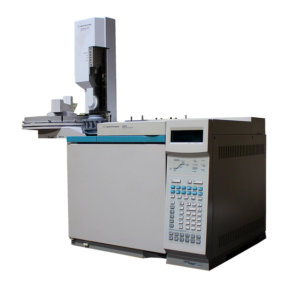
- Page 5 Overview Nitrogen-phosphorus detector Makeup gas regulator (nonEPC only) Flow manifold (early version) Power switch Printed circuit board...
-
Page 6: Preparing The Gc
Preparing the GC Preparing the GC WARNING Hazardous voltages are present in the mainframe when the GC is plugged in. Avoid a potentially dangerous shock hazard by unplugging the power cord before removing the side panels. Turn off the GC and unplug the power cord. Allow time for all heated zones to cool and then turn off supply gases at their sources. - Page 7 Preparing the GC Loosen the five captive screws in the top rear panel with a T-20 Torx screwdriver. Grasp the panel at each end and gently lift it up and away from the GC. Be careful not to disrupt the supply tubing. Pneumatics cover RFI cover Makeup gas regulator...
- Page 8 Preparing the GC Remove the electronics side cover. Loosen the two captive screws at the top, slide the panel to the rear, and lift it off. Captive screws Remove the electronics top cover. Push in on the tab underneath the back of the cover and lift it off.
-
Page 9: Installing The Flow Manifold
Installing the flow manifold Installing the flow manifold This section describes the installation of the current version of the manifold. For information about the early version, see the Appendix. Caution Always hold the manifold by its support bracket to avoid damaging board components. - Page 10 Installing the flow manifold Bracket is flush with carrier rails Figure 2. Manifold, after installation Route the gas tubing behind the manifold, over the top of the chassis, and through the slots. Connect the ribbon cable to the mating connector on the pneumatics board.
- Page 11 Using a pair of needle-nosed pliers, remove the appropriate top rear panel detector cutout for the NPD. Also remove any cutouts needed to access other manifolds or accessories installed in the GC. See Figure 4.
- Page 12 Installing the flow manifold Connect the source gas lines to the manifold. Figure 5. Gas line connections Restore gas pressures and leak test the fittings.
-
Page 13: Installing The Makeup Gas Regulator (Nonepc Detectors)
Installing the makeup gas regulator (nonEPC detectors) Installing the makeup gas regulator (nonEPC detectors) Install a screw in the front or back position of the pneumatics carrier. Do not tighten the screw. Install a screw in the makeup gas regulator. Do not tighten the screw. Screw Back Front... - Page 14 Installing the makeup gas regulator (nonEPC detectors) connecting the air and hydrogen tubing (labeled at the back of the instrument) to the flow manifold. Hydrogen Makeup gas regulator Locate the RFI cover that you removed in Preparing the GC. Remove the front or back rectangular cutout on the cover.
-
Page 15: Positioning And Securing The Detector
Positioning and securing the detector Positioning and securing the detector Remove the round metal cutout on the oven top and the square plastic cutout in the electronics carrier in the front or back detector position, if necessary. Cut the metal circle with diagonal cutters so that the nibs are connected to the piece removed. - Page 16 Positioning and securing the detector Method 1: Use a sharp knife to cut out the insulation using the scribed circle as a guide. Method 2: Pierce the insulation with a screwdriver. Rotate the screwdriver around the scribed circle to remove excess insulation. Clean up any pieces of insulation that fall inside the oven.
-
Page 17: Connecting The Detector
Connecting the detector Connecting the detector Caution Board components can be damaged by static electricity; use a properly grounded static control wrist strap when handling the board. Remove the PC board from its static control bag, slide it into the front or back slot on the main circuit board and plug it into the main board. - Page 18 Connecting the detector Attach the bead and signal cables to the PC board. Bead cable Signal cable Signal connector PC board Bead connector...
- Page 19 Connecting the detector Connect the heater/sensor cable to the square connector closest to the front or back detector. Heater/sensor cable Heater/sensor connector (back position) Heater/sensor connector (front position)
-
Page 20: Routing The Tubing
Routing the tubing Routing the tubing Route the tubing from the flow manifold through the slots in the top of the carrier to the detector area. Front detector tubing Back detector tubing... -
Page 21: Installing The Nutwarmer Cup (Adaptable Npd)
Installing the nutwarmer cup (adaptable NPD) Installing the nutwarmer cup (adaptable NPD) Install the insulation in the cup. Push the wire spring lever at the bottom of the cup to the right to uncover the hole. From inside the oven, place the cup over the detector fitting so that the top of the cup touches the top of the oven. -
Page 22: Restoring The Gc To Operating Condition
Reinstall the electronics top cover. Plug in the GC and turn it on. Press [Front Det] or [Back Det]. If the detector has been properly installed, you will see the following display: NonEPC FRONT DET (NPD) FRONT DET (NPD) Temp Off < Temp Off <... - Page 23 Reinstall the RFI cover. 10. Replace the pneumatics top cover. 11. Plug in the GC and turn it on. 12. If your GC did not detect the new NPD, check the following connections: • Detector card to main board •...
-
Page 24: Appendix: Installing The Pneumatics Module (Early Version)
Appendix: Installing the pneumatics module (early version) Appendix: Installing the pneumatics module (early version) Caution Board components can be damaged by static electricity; use a properly grounded static control wrist strap when removing the electronics covers. From the back of the GC, locate the pneumatics carrier. Pneumatics carrier If you are installing a detector in the front position and an inlet is installed in the back position, unplug the back inlet ribbon cable. - Page 25 Appendix: Installing the pneumatics module (early version) Locate the troughs in the flow manifold and the ridges in the pneumatics carrier. Slide the flow manifold into the carrier, lining up the ridges and troughs. Back detector Front detector Ridges Troughs Flow manifold Plug the ribbon cable into the front or back connector.
- Page 26 Appendix: Installing the pneumatics module (early version) From the front of the GC, secure the flow manifold to the carrier by tightening the captive screw until snug using a T-20 Torx screwdriver. Front captive screw Back captive screw...
- Page 28 Printed on recycled paper. This product is recyclable. Agilent Technologies, Inc. Printed in USA AUG 2001 G1534-90347...