Advertisement
SV9501/SV9502/SV9601/SV9602
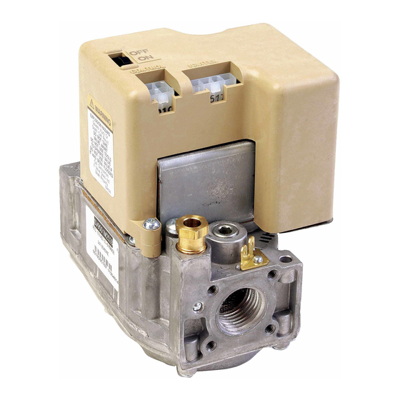
SmartValve
APPLICATION
The Honeywell TRADELINE® SmartValve
Controls provide easy field replacement of a wide range
of SV9500, SV9501, SV9502 and SV9602 SmartValve
System models. Gas appliance manufacturers use these
models in many types of gas fired heating appliances
including central furnaces, residential boilers, rooftop
furnaces, commercial cooking appliances, and unit
heaters. These TRADELINE® controls provide
intermittent pilot gas ignition sequencing, pilot flame
sensing, and both pilot and main gas control functions in
a single control. They are directly compatible with the
Q3450 or Q3480 Intermittent Pilot burners used with the
original controls on the appliance.
The TRADELINE® SV9501 and SV9502 SmartValve
models are replacement controls only for the SV9500,
SV9501, and SV9502 models noted in Table 5. Do not
use these controls to replace other types of intermittent
pilot or direct ignition controls. Do not use these controls
TM
to replace SmartValve
Replacement table. The controls might fit, but the gas
flow control functions might not be compatible with the
appliance.
The TRADELINE® SV9602 SmartValve
replacement controls only for the SV9500P, SV9501P,
SV9502P, SV9600P and SV9601P models noted in Table
5. The SV9602 is a prepurge, step-opening model.
IMPORTANT
Do not use these controls to replace
TM
SmartValve
replacement table.
Prepurge is nominally 30 seconds.
The step opening function provides a timed step outlet
pressure at the start of each heating cycle to allow main
burner ignition at reduced outlet pressure.
Reducer bushings are provided with the SV9602 and
SV9601 models for adapting to smaller pipe sizes.
TM
System Control
TM
System
models not listed in the
TM
models are
models not listed in the
IMPORTANT
Carefully determine the full Honeywell model
number of the existing control. Use Table 4 or
Table 5 to make sure the replacement control
model is suitable for replacing the original
TM
control. If the control is not suitable, obtain the
correct TRADELINE® replacement control as
shown in Table 4 or Table 5, or contact the
appliance manufacturer for the proper
replacement control.
INSTALLATION
When Installing this Product...
1. Read this instructions carefully. Failure to follow
TM
the instructions as written can damage the product
or cause a hazardous situation.
2. Check the relevant chart and the ratings given in
these instructions and on the specific model to
make sure the product is suitable for the
application.
3. Installer must be a trained, experienced, licensed
(if required by local ordinance) technician.
4. Use these instructions to check product operation
after completing installation.
IMPORTANT
Make sure the control being replaced is
defective. See Fig. 13 through 16 for SV9500,
SV9501, and SV9502 Sequence of Operation
and Troubleshooting procedures.
Planning the Installation
WARNING
Fire or Explosion Hazard.
Can cause severe injury, death or property
damage.
Follow these warnings exactly as written.
1. Plan the installation as outlined in this section.
2. Plan for frequent maintenance as described in
the Maintenance section of this manual.
Intermittent pilot systems used on heating equipment in
barns, greenhouses, and commercial properties, and on
heating appliances such as commercial cookers,
agricultural equipment, and pool heaters make heavy
INSTALLATION INSTRUCTIONS
69-1270-3
Advertisement
Table of Contents

Related Manuals for Honeywell TRADELINE SV9501


Summary of Contents for Honeywell TRADELINE SV9501
- Page 1 SmartValve System Control INSTALLATION INSTRUCTIONS APPLICATION IMPORTANT Carefully determine the full Honeywell model number of the existing control. Use Table 4 or The Honeywell TRADELINE® SmartValve System Table 5 to make sure the replacement control Controls provide easy field replacement of a wide range...
-
Page 2: Corrosive Chemicals
SV9501/SV9502/SV9601/SV9602 SMARTVALVE SYSTEM CONTROL Installation demands on the controls. Special steps are recommended to prevent nuisance shutdowns and control failures due to frequent cycling, or severe environmental conditions such as exposure to moisture, corrosive WARNING chemicals, dust, or excessive heat. Following are the possible causes of shutdown and the preventative Fire or Explosion Hazard. - Page 3 SV9501/SV9502/SV9601/SV9602 SMARTVALVE SYSTEM CONTROL Use of Pipe Adapters Ignition system controls are set at the factory for natural or LP gas. Do not attempt to use an ignition control made In some field service applications, space limitations make for LP gas on a natural gas system. Do not attempt to use it difficult or impossible to thread the gas control onto the an ignition control made for natural gas on an LP gas gas supply line.
-
Page 4: Installing The Control
SV9501/SV9502/SV9601/SV9602 SMARTVALVE SYSTEM CONTROL DROP PIPED IGNITION HORIZONTAL SYSTEM CONTROL SUPPLY RISER IGNITION SYSTEM PIPED CONTROL 3 IN. SUPPLY (76 MM) MINIMUM DROP HORIZONTAL 3 IN. TUBING (76 MM) MINIMUM VALVE OUTLET SUPPLY FLANGE IGNITION 9/64 INCH HEX SCREWS (4) M17142 SYSTEM CONTROL... - Page 5 SV9501/SV9502/SV9601/SV9602 SMARTVALVE SYSTEM CONTROL 4. Unscrew the brass compression fitting from the pilot outlet. IGNITION 5. Slip the fitting over the tubing and out of the way. IMPERFECT SYSTEM THREADS CONTROL 6. Push the tubing into the pilot gas outlet. 7.
- Page 6 SV9501/SV9502/SV9601/SV9602 SMARTVALVE SYSTEM CONTROL NOTE: If the wiring harness is damaged, contact the equipment manufacturer for a replacement harness. 120/240 VAC POWER PILOT BURNER GROUND SUPPLY 1. Make sure the power rating on the ignition system (THROUGH PILOT TUBING) NEMA 40 VA TRANSFORMER matches the available supply.
-
Page 7: Startup And Checkout
SV9501/SV9502/SV9601/SV9602 SMARTVALVE SYSTEM CONTROL STARTUP AND CHECKOUT D892 VENT DAMPER WARNING CABLE AND CONNECTOR Fire or Explosion Hazard. TO SUIT Can cause severe injury, death or property damage. Do not force the ignition switch on the appliance. AQUASTAT CONTROL Do not use tools to move the ignition switch. If the switch does not move by hand, a qualified service ROLLOUT technician must replace the control. - Page 8 SV9501/SV9502/SV9601/SV9602 SMARTVALVE SYSTEM CONTROL Turning on the System Push the switch to the ON position. 3/8 TO 1/2 IN. Turning on the Main Burner (10 TO 13 MM) PROPER FLAME Follow the instructions provided by the appliance ADJUSTMENT manufacturer or turn up the thermostat to call for heat. If the main burner does not light, refer to the troubleshooting GROUND table.
-
Page 9: Maintenance
SV9501/SV9502/SV9601/SV9602 SMARTVALVE SYSTEM CONTROL Standard Pressure Regulator (M Models), 5. If the inlet pressure is in the factory specified nominal range, as shown in Table 2 and 3, replace Slow Open (H models), Step Open (P the ignition system control. Otherwise, take the Models) necessary steps to provide proper gas pressure to the control. -
Page 10: Sequence Of Operation
SV9501/SV9502/SV9601/SV9602 SMARTVALVE SYSTEM CONTROL INSTRUCTIONS TO THE Replace the system if any of the following conditions occur: HOMEOWNER • The system does not perform properly at checkout or troubleshooting. • The gas control switch is difficult to move. WARNING • The gas control has operated for more than 200,000 cycles. -
Page 11: Operating Sequence
SV9501/SV9502/SV9601/SV9602 SMARTVALVE SYSTEM CONTROL Complete Shutdown NOTE: The SV9502 and SV9602 have an approximately 30-second prepurge delay before 1. Turn off the power to the appliance. start of Ignition Trial. Be sure to wait for prepurge 2. Move the ignition system control switch to OFF to be completed. -
Page 12: Troubleshooting
SV9501/SV9502/SV9601/SV9602 SMARTVALVE SYSTEM CONTROL SV9501/SV9502/SV9601/SV9602 SmartValve® FAMILY SEQUENCE OF OPERATION START APPLY 24 VAC TO APPLIANCE THERMOSTAT CALLS FOR HEAT FIVE-MINUTE RETRY DELAY PREPURGE/ SYSTEM CHECK PREPURGE (SV9502/SV9602 ONLY) • WAIT FOR FLAME SIGNAL TO DISAPPEAR. FLAME SIGNAL DETECTED? • PILOT VALVE/IGNITER REMAIN OFF INTERNAL CHECK OKAY? TRIAL •... - Page 13 SV9501/SV9502/SV9601/SV9602 SMARTVALVE SYSTEM CONTROL SV9500SV9600 SmartValve™ TROUBLESHOOTING SEQUENCE INSET A END VIEW OF CONTROL 24 VOLT HARNESS THERMOSTAT NOTE: BEFORE TROUBLESHOOTING, CONNECTOR OR PRESSURE BECOME FAMILIAR WITH THE STARTUP SWITCH AND CHECKOUT PROCEDURE. ALSO START OUTPUT CHECK PILOT BURNER ELEMENT FOR •...
- Page 14 SV9501/SV9502/SV9601/SV9602 SMARTVALVE SYSTEM CONTROL SV9501/SV9502/SV9601/SV9602 SmartValve™ TROUBLESHOOTING SEQUENCE INSET A END VIEW OF CONTROL 24 VOLT HARNESS THERMOSTAT NOTE: BEFORE TROUBLESHOOTING, CONNECTOR OR PRESSURE BECOME FAMILIAR WITH THE STARTUP SWITCH START AND CHECKOUT PROCEDURE. ALSO • TURN OFF GAS SUPPLY OUTPUT CHECK PILOT BURNER ELEMENT FOR •...
-
Page 15: Pressure Regulator Setting
Regulator setting in replacement control differs from original. Adjust to rated pressure as necessary for optimum performance. Shipped by Honeywell as LP gas only; may have been converted to natural gas. Use Natural to LP gas conversion kit (included) if necessary. Follow instructions in conversion kit. - Page 16 SV9602P4824 as the replacement. Automation and Control Solutions Honeywell International Inc. Honeywell Limited-Honeywell Limitée 1985 Douglas Drive North 35 Dynamic Drive Golden Valley, MN 55422 Toronto, Ontario M1V 4Z9 customer.honeywell.com ® U.S. Registered Trademark © 2006 Honeywell International Inc. 69-1270—3 M.S. Rev. 08-06...