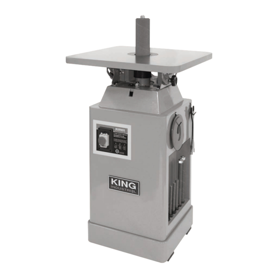
Summary of Contents for King Industrial KC-OVS-FX3
- Page 1 09/2016 instrUction ManUal MODEL: KC-OVS-FX3 COPYRIGHT © 2016 ALL RIGHTS RESERVED BY KING CANADA TOOLS INC.
-
Page 2: Warranty Information
warranty inForMation 2-year king canada tools liMited warranty oFFers a 2-year liMited warranty For tHis oscillating spindle sander intended For coMMercial Use prooF oF pUrcHase Please keep your dated proof of purchase for warranty and servicing purposes. replaceMent parts Replacement parts for this product are available at our authorized King Canada service centres across Canada. liMited tool warranty King Canada makes every effort to ensure that this product meets high quality and durability standards. - Page 3 general & speciFic saFety rUles 1. know yoUr tool watch) because they could get caught in moving parts. Non-slip Read and understand the owners manual and labels affixed to the footwear is recommended. Wear protective hair covering to contain tool. Learn its application and limitations as well as its specific po- long hair.
- Page 4 6) Table tilt lock knob (2) 13) 4” cast-iron dust chute 7) Two adjustment keys & storage hook 14) Tilting table 90 stop bolt spindle sander specifications MODEL KC-OVS-FX3 Oscillations per minute Oscillations stroke 1-1/2” Spindle drum length 10 (5” - 9”) Spindle diameter 1/4”...
-
Page 5: Electrical Information
electrical inForMation warning! ALL ELECTRICAL CONNECTIONS MUST BE DONE BY A QUALIFIED ELECTRICIAN. FAILURE TO COMPLY MAY RESULT IN SE- RIOUS INJURY! ALL ADJUSTMENTS OR REPAIRS MUST BE DONE WITH THE MACHINE DISCONNECTED FROM THE POWER SOURCE. FAILURE TO COMPLY MAY RESULT IN SERIOUS INJURY! power sUpply 110V eXtension cords warning: YOUR SPINDLE SANDER MUST BE CONNECTED TO A... -
Page 6: Assembly And Adjustments
asseMbly & adJUstMents warning! IF ANY PART IS MISSING OR DAMAGED, DO NOT PLUG THE SPIN- DLE SANDER IN UNTIL YOU HAVE REPLACED THE MISSING OR DAMAGED PART. For your safety, complete the assembly of the spindle sander before plugging it into the power supply. - Page 7 asseMbly & adJUstMents installing tHe appropriate table insert warning: FAILURE TO USE THE PROPER INSERT WITH THE CORRESPON- DING SPINDLE MAY RESULT IN INJURY AND/OR DAMAGE TO THE MACHINE OR THE WORKPIECE. 1. This machine comes three table inserts. When changing spindles, the table insert will need to be changed to the matching size.
- Page 8 adJUstMents & operation tUrning tHe sander on/oFF This sander comes with a 2 step activation safety switch, refer to Fig.11, which starts and stops the machine. To turn the sander on; 1. Push up on the emergency stop button (A) Fig.11 and lift the switch cover (B) upwards as shown.
-
Page 9: Maintenance
Maintenance & troUblesHooting warning! FOR YOUR OWN SAFETY, TURN THE SWITCH OFF AND REMOVE PLUG FROM THE POWER SOURCE BEFORE PERFORMING MAINTENANCE, CLEANING OR LUBRICATION WORK ON THE SPINDLE SANDER. cleaning / lUbricating 1. Blow out dust accumulation and wood chips inside the motor, housing, and dust chute frequently.


