Table of Contents
Advertisement
Advertisement
Chapters
Table of Contents

Related Manuals for Omron 3F88L-160


Summary of Contents for Omron 3F88L-160
- Page 1 Cat. No. O008-E1-04 USER’S MANUAL 3F88L-160/162 Cam Positioner...
- Page 2 Please read this manual thoroughly and handle and operate the product with care. 1. To ensure safe and proper use of the OMRON Cam Positioners, please read this USER’S MANUAL (Cat. No. O008-E1) to gain sufficient knowledge of the devices, safety information, and precautions before actual use.
- Page 3 OMRON Product References All OMRON products are capitalized in this manual. The word “Unit” is also capitalized when it refers to an OMRON product, regardless of whether or not it appears in the proper name of the product. The abbreviation “Ch,” which appears in some displays and on some OMRON products, of- ten means “word”...
- Page 4 It is extremely important that a PC and all PC Units be used for the specified purpose and under the specified conditions, especially in applications that can directly or indirectly affect human life. You must consult with your OMRON representative before applying a PC System to the above-mentioned applications.
- Page 5 General Precautions Caution Fail-safe measures must be taken by the customer to ensure safety in the event of incorrect, missing, or abnormal signals caused by broken signal lines, momentary power interruptions, or other causes. Caution Always use the power supply voltages specified in the operation manuals. Caution Take appropriate measures to ensure that the specified power with the rated voltage and frequency is supplied.
- Page 6 Caution Be sure that cables and other items with locking devices are properly locked into place. Caution Always turn OFF the power supply to the Unit before attempting any of the following. S Assembling the Unit. S Setting switches. S Connecting cables or wiring the system. S Connecting or disconnecting the connectors.
- Page 7 EC Directives will vary depending on the configuration, wiring, and other conditions of the equipment or control panel in which the OMRON devices are installed. The customer must, therefore, perform final checks to confirm that devices and the overall machine con- form to EMC standards.
- Page 8 Conformance to EC Directives The 3F88L-160/162 Cam Positioner complies with EC Directives. To ensure that the system in which the 3F88L-160/162 is installed complies with EC Directives, the following precautions must be ob- served. 1. The 3F88L-160/162 is defined as an in-panel device according to the Low-voltage Directive.
- Page 9 Omron’s exclusive warranty is that the Products will be free from defects in materials Warranty and workmanship for a period of twelve months from the date of sale by Omron (or such other period expressed in writing by Omron). Omron disclaims all other war- ranties, express or implied.
- Page 10 It may represent the result of Omron’s test conditions, and the user must correlate it to actual application requirements. Actual performance is subject to the Omron’s Warranty and Limitations of Liability.
- Page 11 USER’S MANUAL 3F88L-160/162 Cam Positioner...
-
Page 12: Table Of Contents
Table of Contents Chapter 1. Outline ......... . 1-1 Functions . - Page 13 Table of Contents 3-6 Applied Functions ............3-44 3-6-1 Function Level Selection Setting (SET Mode) .
- Page 14 Table of Contents 7-5 Displays by Mode ............7-12 7-6 Error Codes .
-
Page 15: Chapter 1. Outline
Chapter 1 Outline Functions System Configuration Name and Function of Each Part Glossary Operation Procedure... -
Page 16: Functions
Resolver (a sensor that detects absolute angles) and turn output signals ON and OFF at a preset angle through a cam program. The 3F88L-160 Cam Positioner has 16 cam output points and the 3F88L-162 Cam Posi- tioner has 32 cam output points. -
Page 17: Modes
Note 2. A bank is a program unit made up of cam outputs 1 to 32 for the 3F88L-162 and cam outputs 1 to 16 for the 3F88L-160. By changing the bank, the program that will be operated will change. -
Page 18: Initial Settings Functions
Outline Chapter 1 H Data Save • Saves parameters and cam programs in non-volatile memory (EEPROM). As the data is stored in non-volatile memory, battery replacement, and other maintenance is not required. H Program Number Check • The number of programs and origin compensation angle can be checked. (Refer to 3-5-3 Cam Pro- gram Creating and Checking.) 1-1-6 Initial Settings Functions H Switching Resolution... - Page 19 (Refer to Chapter 4 Communications.) Note CompoWay/F is a uniform procedure in OMRON serial communications. CompoWay/F has uni- form frame formats and commands that conform to FINS (Factory Interface Network Service) that is used in OMRON PCs.
-
Page 20: System Configuration
Control I/O signal SYSMAC CS1-series PC or other PC G7TC-OC16 I/O Block 3F88L-160 or 3F88L-162 Cam Positioner Detection Section M7E or M7F Display Unit Note Refer to 2-3 Wiring or 7-4 Standard Models for information on various connection cables. -
Page 21: Name And Function Of Each Part
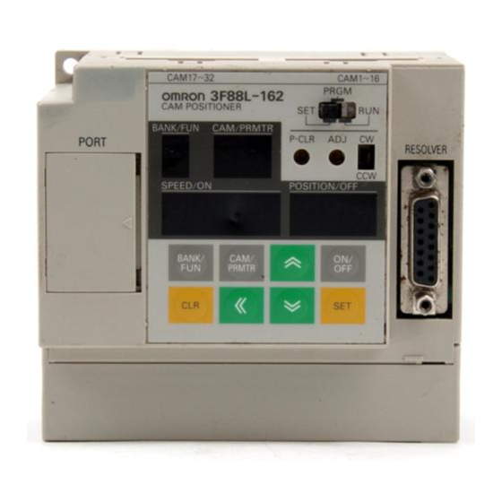
Outline Chapter 1 Name and Function of Each Part 1. Bank/Function display 2. Cam/Parameter No. display 5. Mode selection switch 11. Cam output 6. P⋅ CLR switch connector (top) 7. ADJ switch 8. CW/CCW setting switch Mounting hole 12. Commu- 10. -
Page 22: Display Section
Outline Chapter 1 1-3-1 Display Section • Displays the operation status, error status, and settings data. • The data displayed will differ depending on the mode. Name Mode Display 1. Bank and function display Display the number of the operating bank. PRGM Display the number of the bank being programmed. -
Page 23: Operation Keys
Outline Chapter 1 1-3-3 Operation Keys Name Mode Function Bank/Function Key PRGM/SET Increases bank and function numbers. BANK/ Cam/Parameter Key Increases cam and parameter numbers. CAM/ PRMTR ON/OFF Switching Key Switches between ON and OFF angles. Up Key Increases the numeral that is flashing. Down Key Decreases the numeral that is flashing. -
Page 24: Glossary
Resolver The Resolver is a sensor that detects the absolute angle. One of four Resolver models (3F88L-RS17, 3F88L-RS17T, 3F88L-RS15, and 3F88L-RS15W) can be selected for 3F88L-160 and 3F88L-162 Cam Positioners. Trial operation When in PRGM mode, this function can be used to adjust the cam output ON and OFF angles by using the operation keys in order to check mechanical operation. -
Page 25: Operation Procedure
Outline Chapter 1 Operation Procedure 1-5-1 Before Operation H Basic Use • The procedure for using the Cam Positioner at function level 1 (basic operation/monitor only) is out- lined below. Procedure Contents Reference section Installation Install the Cam Positioner according to the installation environment conditions. - Page 26 Outline Chapter 1 S When using the teaching function. S When making pulse output, cam data protect, output hold, one-direction function, and present value output settings. H Applied Functions • The procedure for using the Cam Positioner at function level 2 (all functions) is outlined below. Procedure Contents Reference...
-
Page 27: Chapter 2. Design
Chapter 2 Design System Design Installation Wiring... -
Page 28: System Design
Design Chapter 2 System Design WARNING Take safety measures outside the Cam Positioner to ensure safety for the entire system in the event of Cam Positioner failure or error caused by factors external to the Cam Positioner. Faulty operation may result in a serious accident. S Emergency stop circuits, interlock circuits, limit circuits, and similar safety mea- sures must be included in control circuits outside the Cam Positioner. - Page 29 Design Chapter 2 H Cam Positioner and Resolver Configuration 3-m Plug-in cable 3F88L-160 or 3F88L-162 3F88L-CRjjjC 3F88L-RS17/-RS17T Cam Positioner Resolver Extension Cable Resolver Connector type 3F88L-160 or 3F88L-162 3F88L-CRjjjNA 3F88L-RS15 Resolver Cam Positioner Resolver Cable 35-cm Separate wire plug-in cable...
-
Page 30: Selecting The Output Device
Select the device and connection method for ON/OFF outputs from the Cam Positioner. (Refer to 2-3 Wiring for information on connecting output devices.) H For Relay Output Use an I/O Block for relay output. 3F88L-160 or 3F88L-162 3F88L-CGjjjN G7TC-OC16 Cam Positioner... - Page 31 Design Chapter 2 H To Display Present Angles and Other Data on a Display Unit Connect a M7E or M7F Display Unit to the Cam Output Cable. 3F88L-160 or 3F88L-162 3F88L-CGjjjS M7E or M7F Display Unit Cam Positioner Cam Output Cable Note Parameters must be set to output present values.
-
Page 32: Installation
Design Chapter 2 Installation 2-2-1 External Dimensions Note All units are in millimeters unless otherwise indicated. H 3F88L-160 and 3F88L-162 Cam Positioners Two, 4.5 dia. 101±0.2 w When the Resolver Cable is connected... - Page 33 Chapter 2 Resolvers 3F88L-RS17 and 3F88L-RS17T 280.5 72 (81) (see note) Four, 4.5 dia. 50 0.3 dia. XM3A-1521 (OMRON) or the equivalent 15-pin D-sub Plug 8.6 dia. Approx. 3 m 8.6 dia. XM3D-1521 (OMRON) or the equivalent 15-pin D-sub Socket Note The dimensions in parentheses are for the 3F88L-RS17T Resolver.
-
Page 34: Installation Environment
Design Chapter 2 D 3F88L-RS15W max. 350 max. 16.5±0.5 2-2-2 Installation Environment Take precautions with the installation environment to improve the reliability and to fully utilize the functions of the Cam Positioner system. H Do not install the Unit in the following locations. •... -
Page 35: Mounting The Resolver
Design Chapter 2 H Conformance to EC Directives The 3F88L-160/162 Cam Positioner complies with EC Directives. To ensure that the system in which the 3F88L-160/162 is installed complies with EC Directives, the following precautions must be ob- served. • The 3F88L-160/162 is defined as an in-panel device according to the Low-voltage Directive. The 3F88L-160/162 must, therefore, be installed within a control panel. - Page 36 Design Chapter 2 D 3F88L-RS15/15W (Servo-mounted) w Recommended w Mounting example mounting hole Three, M4 screws (Evenly spaced around circumference) +0.025 33.332 +0.009 dia. 52 dia. 52 dia. 67 dia. 3-mm sheet min. w Mounting hook (Resolver attachment) 4.4 dia. H Connecting with the Coupling As a rule, the Resolver Coupling should be used when connecting the Resolver to the machinery.
- Page 37 Design Chapter 2 Note 2. Maximum bend angle Θ1 Note 3. Axle center displacement D Precautions when Connecting with the Coupling Take the following precautions when connecting the Resolver to the machinery via the Coupling. • Make sure the axle center does not protrude into the area marked C in the diagram. If the axle center is protruding when the Resolver rotates, the Coupling will no longer function and the machinery may be damaged.
- Page 38 Design Chapter 2 D Connection Examples Using a Timing Belt A pulley is attached directly onto the Resolver axle and connected to a rotating machinery by a timing belt. In this case, the load on the axle is the tension on the timing belt and the weight of the pulley. Timing belt Resolver Using Gears...
-
Page 39: Wiring
SYSMAC CS1 or other Display Units Programmable Controller 3F88L-CGjjjN 3F88L-CGjjjS 3F88L-CGjjjS Cam Output Cable Cam Output Cable Cam Output Cable Cam Output Connector 3F88L-160/162 Cam Positioner Resolver Connection Cables 3F88L-CRjjjC 3F88L-CRjjjNA 3F88L-CRjjjSA Resolver Extension Cable Resolver Cable Resolver Cable 3F88L-RS17/-RS17T Resolver... -
Page 40: Standard Wiring Method
Give sufficient consideration to noise countermeasures when wiring H Using Connection Cables Use the following Cables to connect the Unit to peripheral devices. Always use OMRON Cables when connecting the Resolver, in particular, to ensure reliability of the Unit. Peripheral device... - Page 41 • If using metal conduit or running wires through metal duct, ground the metal to one point. Note To make the 3F88L-160/162 Cam Positioner conform to EC Directives, be sure to install the Unit within a control panel.
-
Page 42: Terminal Block Wiring
Design Chapter 2 S Use a separate grounding system. S Attach a surge absorber or diode to the device or parts generating the noise, as shown in the fol- lowing diagram. AC relays or AC valves DC relays Surge absorber Diode power power... - Page 43 Design Chapter 2 D Terminal Functions Terminal name Symbol Function Recommended connection wire diameter Main circuit power supply Inputs the AC power supply for the Cam 1.25 mm AC1/L input terminal input terminal Positioner. Provide a 100 to 240 V AC Positioner.
- Page 44 Design Chapter 2 D Terminal Functions Terminal Function Recommended Symbol name connection wire diameter Control I/O The control I/O power supply terminal is used for the power 1.25 mm 24 V power supply for control I/O. pp y supply Provide a 24-V DC power supply. (Rated power supply voltage 20.4 to 26.4 V DC) Operation START...
- Page 45 Design Chapter 2 D Control Input Specifications Item Specification Rated input voltage 24 V DC –15%/10% Input impedance 4.7 kΩ Input current 4.7 mA TYP. (for 24 V DC input) ON voltage 17 V min. between 24-V terminal and control input terminals. OFF voltage 5 V max.
- Page 46 Design Chapter 2 Note 1. Use M3.5 round or forked crimp terminals for functional ground and protective ground termi- nals. w Round crimp terminal w Forked crimp terminal 6.2 mm 6.2 mm max. max. Note 2. Reinforced insulation or double insulation must be used for the DC power supplies used as I/O power supplies in order to comply EC Directives.
-
Page 47: Resolver Wiring
Chapter 2 2-3-4 Resolver Wiring Use OMRON Resolver Cables which are designed to reduce noise. Resolver Cables transfer signals that require a high degree of accuracy. Separate the Resolver Cables from other cables as much as possible to prevent the accuracy being affected by induction noise resulting from low signal voltage. -
Page 48: Cam Output Wiring
Note Cam output is also used for connection to Display Units. Refer to 2-3-6 Connecting a Display Unit for details. Cam Output Connectors CAM17 to 32 CAM1 to 16 G7TC-OC16 I/O Block 3F88L-CGjjjN Cam Output Cable PC or Relay 3F88L-160/162 3F88L-CGjjjS Cam Positioner Cam Output Cable 2-22... - Page 49 Design Chapter 2 Note The 3F88L-160 16-output Cam Positioner does not have cam output connector terminal numbers CAM17 to CAM32. D Cam Output Cable Models Cam Output Cables for Connection to I/O Blocks 0.5 m 3F88L-CG0R5N 3F88L-CG001N Cam Output Cables for Connection to Other Devices...
- Page 50 17 to 32 (CAM17 to CAM32). These connectors are not available on the 3F88L-160 16-point Cam Positioner. Note 3. The maximum switching capacity for cam outputs is 26.4 V DC, 300 mA. However, keep this at no more than 1.6 A per connector.
-
Page 51: Connecting A Display Unit
Some cam output signals can no longer be used, therefore, when pres- ent values are being output. H Connecting a M7E Display Unit Use a 3F88L-CGjjjS Cam Output Cable to connect the M7E Display Unit. 3F88L-160/162 Cam Positioner 3F88L-CGjjjS Cam Output Cable M7E Display Unit D Functions The present angle (in degrees) or the Resolver speed (r/min) can be displayed on a 3- or 4-digit Display Unit. - Page 52 Design Chapter 2 If set to an automatically switching display, the present angle will be displayed when the Resolver speed is less than 4 r/min and the Resolver speed will be displayed when it is greater than 4 r/min. D Unit Models Used Name Model Remarks...
- Page 53 Note 1. If pin 9 (4th digit) is left open, a zero (0) will appear as “0.” In the above wiring example, an output of 0 would appear as “0000.” Note 2. The cam output signal names not in parentheses will be displayed for 3F88L-160 Cam Posi- tioners and the names in parentheses will be displayed for 3F88L-162 Cam Positioners.
- Page 54 Note Write “deg” in the space when using a no display Unit. H Connecting a M7F Display Unit Use a 3F88L-CGjjjS Cam Output Cable to connect the M7F Display Unit. 3F88L-160/162 M7F Display Unit 3F88L-CGjjjS Cam Positioner Cam Output Cable...
- Page 55 Case mark Note 1. The cam output signal names not in parentheses will be displayed for 3F88L-160 Cam Posi- tioners and the names in parentheses will be displayed for 3F88L-162 Cam Positioners. Note 2. The circled terminal numbers have been provided for convenience. When assembling the socket, pay attention to the direction of the polarity guide and connect the wires as shown in the above terminal layout.
-
Page 57: Chapter 3. Operation
Chapter 3 Operation Nomenclature of Display and Operation Sections Modes, Functions, and Display Operation Procedure Selecting Function Levels Basic Operation Applied Functions... -
Page 58: Nomenclature Of Display And Operation Sections
Operation Chapter 3 Nomenclature of Display and Operation Sections Bank/Function display Cam/Parameter No. display Mode selection switch P⋅CLR switch ADJ switch CW/CCW setting switch Operation keys Present angle/OFF angle display No. of revolutions/ON angle display H Operation Keys Bank/Function Key Down Key BANK/ Cam/Parameter Key... - Page 59 Operation Chapter 3 H Display Patterns for Seven-segment Display Marks underneath a character display indicate that the character is flashing.
-
Page 60: Modes, Functions, And Display
Operation Chapter 3 Modes, Functions, and Display H Modes The 3F88L-160/162 Cam Positioner has three modes: SET, PRGM, and RUN. Set Mode (SET) Program Mode (PRGM) Operation Mode (RUN) S Unit parameter settings S Creation, editing, and S Normal operation... - Page 61 Operation Chapter 3 Classifi- Classifi- Function name Function name Applicable modes Applicable modes Conditions Conditions Front panel Refer- Refer- cation cation displays ence sec- ence sec- tion tion Function Parame- ter No. Basic Cam program writing PRGM 1 to 8 1 to 32 3-5-3 functions...
- Page 62 Operation Chapter 3 Classifi- Classifi- Function name Function name Applicable modes Applicable modes Conditions Conditions Front panel Refer- Refer- cation cation displays ence sec- ence sec- tion tion Function Parame- ter No. Applied Origin compensation 3-6-4 functions value setting Note Origin com- pensation can also be per- formed as a ba-...
- Page 63 Copy 3-6-13 Baud rate setting 3-6-13 (shared with Com- poWay/F and copy operation.) Note 1. The data for the 3F88L-160 (16-point model) Cam Positioner is shown in parentheses. Note 2. The data for 720 resolution (divisions/revolution) is shown in parentheses.
- Page 64 Operation Chapter 3 H Displays by Mode D SET Mode Bank/Func- Cam/Parame- Function Data range SPEED/ON POSITION/OFF tion 1 to 8 Origin Displays the (1 to 4) compensation absolute angle for (see note 2) absolute angle origin compensation. 1 to 32 Program Displays the number (1 to 16)
- Page 65 Operation Chapter 3 Bank/Func- Cam/Parame- Function Data range SPEED/ON POSITION/OFF tion c (c) Cam protect Protection can be set Protect can be set or or released for each released for each cam number or for cam number or for all cams in a bank all cams in a bank number.
- Page 66 Error display E–** (error display) Note 1. The data for the 3F88L-160 (16-point model) Cam Positioner is shown in parentheses. Note 2. The data for 720 resolution (divisions/revolution) is shown in parentheses. The angles will be set and displayed as “1” for 0.5°.
- Page 67 Control I/O monitor E–** (error display) Note 1. The data for the 3F88L-160 (16-point model) Cam Positioner is shown in parentheses. Note 2. The data for 720 resolution (divisions/revolution) is shown in parentheses. The angles will be set and displayed as “1” for 0.5°.
-
Page 68: Operation Procedure
Operation Chapter 3 Operation Procedure 3-3-1 Before Operation H Basic Use • The procedure for using the Cam Positioner at function level 1 (basic operation/monitor only) is out- lined below. Procedure Contents Reference section Installation Install the Cam Positioner according to the installation environment conditions. - Page 69 Operation Chapter 3 S When using the teaching function. S When setting pulse output, cam protect, output hold, one-direction function, and present value output. H Applied • The procedure for using the Cam Positioner at function level 2 (all functions) is outlined below. Procedure Contents Reference...
-
Page 70: Selecting Function Levels
This function level is for using applied functions. It is recommended, therefore, that cam programs be created and parameters set at level 2 (or level 1) first and then the 3F88L-160/162 Cam Positioner be used at level 0 (or level H Limiting Functions by Function Level The following table shows how functions are limited by the function level settings. - Page 71 Operation Chapter 3 Classifi- Classifi- Function Function Contents Contents Function level Refer- Refer- cation cation ence ence (Moni- (Basic (All opera- func- only) tion/ tions) monitor only) Basic Cam program writing Writes and edits cam 3-5-3 functions programs (settings for cam output ON/OFF angles) Program number checking...
- Page 72 Operation Chapter 3 Classifi- Classifi- Function Function Contents Contents Function level Refer- Refer- cation cation ence ence (Moni- (Basic (All opera- func- only) tion/ tions) monitor only) Basic Con- Input START While the START 3-5-8 functions trol sig- (Start signal is ON in RUN nals operation) mode, the cam...
- Page 73 Operation Chapter 3 Classifi- Classifi- Function Function Contents Contents Function level Refer- Refer- cation cation ence ence (Moni- (Basic (All opera- func- only) tion/ tions) monitor only) Applied Origin compensation value Sets the 3-6-4 functions setting compensation value to match the mechanical origin to the Cam Positioner origin.
- Page 74 Present value output setting Using cam output 3-6-10 signals, outputs signal connecting to M7E, M7F or other Display Units Units. Present value output Note Uses CAM 9(7) function (operation) to 16 for 3F88L-160 and CAM 25 (23) to 32 3F88L-162. 3-18...
- Page 75 Operation Chapter 3 Classifi- Classifi- Function Function Contents Contents Function level Refer- Refer- cation cation ence ence (Moni- (Basic (All opera- func- only) tion/ tions) monitor only) Applied Cam pro- Pulse output Creates cam 3-6-11 functions gram creat- setting programs that turn ON ing/changing and OFF at constant intervals in any bank...
-
Page 76: Basic Operation
Operation Chapter 3 Basic Operation 3-5-1 Function Level Selection Setting (SET Mode) H Function Level Selection Setting and Checking Check if the function level is set to function level 1 (basic operation/monitor only). Change to function level 1 (basic operation/monitor only) if set to a different level. Function level Function Parameter... -
Page 77: Initial Settings
Operation Chapter 3 Operation Display Explanation Press the Set Key to confirm the settings. The setting will stop flashing for approximately 1 second and then resume flashing. Note When a setting is flashing, the Up and Down Keys are enabled and the setting may be changed. - Page 78 Operation Chapter 3 D Relationship between Resolver Rotation Direction and Rotation Direction Selection Increasing angles Increasing angles Direction of increasing angles when Direction of increasing angles when setting switch is set to “CW.” setting switch is set to “CCW.” H Resolution Selection (SET Mode) Select a resolution of either 360 or 720 (divisions/rotation).
- Page 79 Operation Chapter 3 D Procedure Operation Display Explanation Use the mode selection switch to change to SET mode. Keep pressing the Bank/Function Key until “A” appears on the BANK/ Bank/Function display. Note The display for level 1 will change from “1” to “2” through to “8”...
-
Page 80: Cam Program Creating And Checking (Prgm Mode/Set Mode)
Operation Chapter 3 3-5-3 Cam Program Creating and Checking (PRGM Mode/SET Mode) Once the initial settings have been made, turn OFF the power and then turn it ON again. (The initial settings will be enabled once the power has been turned ON again.) Next, create a cam program (cam output ON/OFF patterns) in PRGM mode. - Page 81 Operation Chapter 3 Once a program has been checked for one cam number, change the cam number (using the Cam/Pa- rameter Key) and check another cam program in the same way. If multiple bank numbers are used, change the bank number (using the Bank/Function Key) and check another program in the same way. D Cam Program Deletion (PRGM Mode) There four methods to delete cam programs.
- Page 82 Operation Chapter 3 Deleting by Bank Number (PRGM Mode) Operation Explanation Set the mode selection switch to PRGM mode. Press the Bank/Function Key and set the bank number that is to be BANK/ deleted. Press the Clear Key three times. (The bank number display will start flashing.) Press the Set Key to delete the bank number.
- Page 83 Operation Chapter 3 H Cam Program Creation (PRGM Mode) Before creating cam programs, use the information contained in 7-7 Cam Programming Sheet to write down the ON/OFF patterns so as to make the process easier. D Time Chart The following shows how to create a cam program with the following kind of ON/OFF patterns. The resolution is set to 360 (divisions/rotation) in this example.
- Page 84 Operation Chapter 3 Operation Key Functions Operation keys Functions Bank/Function Key Increases the bank number (used for setting bank numbers.) BANK/ Cam/Parameter Key Increases the cam number (used for setting cam numbers.) CAM/ PRMTR ON/OFF Key Switches between ON and OFF angles. Up Key Increases the numeral currently flashing (used for setting ON and OFF angles.)
- Page 85 Operation Chapter 3 Operation Display example Explanation Set the ON angle. Under the initial settings, the rightmost digit (the first digit) will be flashing. Press the Forward Key to move the position of the flashing digit from the first to the second digit, from the second to the third digit, and then back to the first digit again.
- Page 86 Operation Chapter 3 Operation Display example Explanation In step 2 of cam number 3, set the ON angle to “150” and the OFF angle to “180.” The setting method is the same as outlined previously. Press the Set Key to save the ON and OFF angle settings for step 2.
- Page 87 Operation Chapter 3 H Cam Program Confirmation (PRGM Mode) Once a cam program has been created, check that it has been created correctly. D Procedure Operation Display Explanation Use the mode selection switch to set to PRGM mode. The data for step 1 of the bank and cam numbers displayed will be displayed.
- Page 88 Operation Chapter 3 Operation Display Explanation Check the data for step 3 in the same way. Check data through to the last step. Check the data for all cam programs that have been created. If there are errors in any cam program, follow the procedure outlined in the previous section and set the correct data.
- Page 89 Operation Chapter 3 Operation Display Explanation Press the Cam/Parameter Key and set the cam number that CAM/ contains the step to be deleted. PRMTR The Cam/Parameter No. display will change as shown below when the Cam/Parameter Key is pressed. 1→2→3→...→15→16→1→ etc. Keep pressing the Cam/Parameter Key until the cam/parameter number to be set is displayed.
- Page 90 Operation Chapter 3 Operation Display Explanation Press the Cam/Parameter Key and set the cam number that is CAM/ to be deleted. PRMTR The Cam/Parameter No. display will change as shown below when the Cam/Parameter Key is pressed. 1→2→3→...→15→16→1→ etc. Keep pressing the Cam/Parameter Key until the cam/parameter number to be deleted is displayed.
- Page 91 The number of steps for the displayed bank and cam (1 to 4) (1 to 16) ber checking numbers will be shown in the SPEED/ON display. (see note 2) (see note 1) Note 1. The numeric values for the 3F88L-160 (16-point model) Cam Positioner are shown in parentheses. 3-35...
- Page 92 Operation Chapter 3 Note 2. The numeric values for 720 (divisions/rotation) resolution are shown in parentheses. Bank No. Cam No. Number of steps for the set bank and cam numbers Note When the parameter number (PRMTR) is “0,” the absolute angle for origin compensation is shown in the SPEED/ON display.
-
Page 93: Resolver And Machinery Connection
Operation Chapter 3 3-5-4 Resolver and Machinery Connection Once the cam programs have been completed, turn OFF the power supply (for safety) and connect the Resolver and the machinery. H Resolver and Machinery Connection • Turn OFF the system power supply before connecting the Resolver and machinery. •... -
Page 94: Start Operation (Run Mode)
Operation Chapter 3 Origin Compensation and Origin Shift • Both origin compensation and origin shift functions match the mechanical origin and the Cam Posi- tioner origin. • The differences between origin compensation and origin shift are outlined as follows: Origin Compensation Press the ADJ switch in SET mode to set the present angle at that point to zero. - Page 95 Operation Chapter 3 Operation Display Explanation Bank selection input Use the control input bank selection input (BANK1 to 3) to (BANK1 to 3) o 3) specify the bank number to be used. Set bank number 24 V DC (BANK 1 to 3) E.g.:To set bank No.
-
Page 96: I/O Monitor Function (Run Mode)
Chapter 3 3-5-7 I/O Monitor Function (RUN Mode) The 3F88L-160/162 Cam Positioners have the following monitor functions in RUN mode. If the system does not perform properly at start up, use this monitor function first and check the I/O status. - Page 97 7-segment indicators (lit when signal is OFF). Note The 3F88L-160 (16-point model) Cam Positioner does not have cam outputs 17 to 32. (The relevant indicators will remain OFF.) D Procedure...
-
Page 98: Control I/O Signals
POSITION/OFF (Control input) 3-5-8 Control I/O Signals In addition to cam outputs (CAM 1 to 16/CAM 1 to 32), the 3F88L-160/162 Cam Position- ers also have the control inputs and outputs described below. Refer to 2-3-3 Terminal Block Wiring for information on wiring control I/O signals. - Page 99 Operation Chapter 3 Name Symbol Function Origin shift input TRIG When the origin shift input is turned from OFF to ON in RUN mode, origin shift is executed. Note 1. TRIG input is ignored when the Unit is in modes other than RUN. Note 2.
-
Page 100: Applied Functions
Chapter 3 Applied Functions Function selection (Function No. U) must be set to “2” (all functions) before the applied functions can be used for 3F88L-160/162 Cam Positioners. 3-6-1 Function Level Selection Setting (SET Mode) H Function Level Selection Setting and Checking Check if the function level is set to function level 2 (all functions). -
Page 101: Parameter List (Set Mode)
Operation Chapter 3 Operation Display Explanation Press the Set Key to confirm the settings. The setting will stop flashing for approximately 1 second and then resume flashing. Note When a setting is flashing, the Up and Down Keys are enabled and the setting may be changed. - Page 102 Operation Chapter 3 Bank/Func- Cam/Parame- Function name Setting SPEED/ON POSITION/OFF tion range Origin 0 to 359 Sets origin compensation (0 to 719) compensation value value (see note 2) (angle data). Factory setting “0.” Backlash 0 to 179 Sets backlash compensation (0 to 359) compensation value value...
- Page 103 Operation Chapter 3 Bank/Func- Cam/Parame- Function name Setting SPEED/ON POSITION/OFF tion range One-direction 0 to 2 0: One-direction function setting function disabled (factory setting) 1: Enabled in forward direction 2: Enabled in reverse direction Backlash 0, 1 0: Backlash compensation compensation enable/disable disabled (factory...
- Page 104 2: Function level 2 (all functions) Note 1. The data for the 3F88L-160 (16-point model) Cam Positioner is shown in parentheses. Note 2. The data for 720 resolution (divisions/revolution) is shown in parentheses. The angles will be set and displayed as “1” for 0.5°.
-
Page 105: Parameter Explanation And Operation
H Items to be Checked before Setting Parameters The functions and parameter setting for 3F88L-160/162 Cam Positioners will be explained in the next section. Before proceeding, be sure to check that the following two settings have been made. - Page 106 Operation Chapter 3 H Operation The method for basic parameter display and settings is shown in the following diagram. Change to SET mode (using the mode selection switch) When setting parameters for a different function number. Set the function number with the Bank/Function Key Press the Set Key When setting parameters for the same function number.
- Page 107 Operation Chapter 3 D Setting Parameters Once the parameters have been displayed using the individual operations, perform the following opera- tions to set the parameter data. • Use the Up and Down Keys to increase or decrease the numeric value of the digit that is flashing. •...
- Page 108 Origin compensation Bank number 1, cam number 1, Bank number 1, cam number 32, absolute angle (display) step number (display) step number (display) Up to cam number 16 or 3F88L-160 Keys other Any key than Origin compensation Bank number 2, cam number 1,...
- Page 109 Cam protect (bank number 2, cam number 32) Cam protect (bank number 2) cam number 1) Up to cam number 16 for 3F88L-160 Cam protect (bank number 8, Cam protect (bank number 8, cam number 32) Cam protect (bank number 8)
- Page 110 One-direction function (bank One-direction function setting (bank number 1) number 1, cam number 1) number 1, cam number 32) Up to cam number 16 for 3F88L-160 One-direction function (bank One-direction function (bank One-direction function (bank number 2) number 2, cam number 1)
- Page 111 Pulse output (bank number 1, Pulse output (bank number 1) Pulse output settings cam number 1) cam number 32) Up to cam number 16 for 3F88L-160 Pulse output (bank number 2, Pulse output (bank number 2, Pulse output (bank number 2) cam number 1)
-
Page 112: Origin Compensation And Origin Shift
Operation Chapter 3 3-6-4 Origin Compensation and Origin Shift H Functions • Both origin compensation and origin shift functions match the mechanical origin and the Cam Posi- tioner origin. • The differences between origin compensation and origin shift are outlined as follows: Origin Compensation Press the ADJ switch in SET mode to set the present angle at that point to zero. - Page 113 Operation Chapter 3 • When the origin compensation value is “200” (resolution: 360) Present angle before compensation Y Execution position for origin compensation/origin shift Present angle after compensation H Related Parameters (SET Mode) Function level D Origin Compensation Value Function Parameter Setting range 0 to 359 (0 to 719) (see note 1) •...
- Page 114 Operation Chapter 3 Function level D Origin Compensation Absolute Angle (Display) Function 1 to 8 (1 to 4) Parameter Setting range (Display only) (see note) • Use this parameter to display the origin compensation absolute angle (origin position after origin com- pensation or origin shift for the Resolver’s electrical 0°) in the SPEED/ON display.
- Page 115 Operation Chapter 3 H Origin Shift Execution (RUN Mode) D Procedure Operation Display Explanation Use the mode selection switch to change to RUN mode. (Manual Rotate the machinery to the position to be set as zero (or to the origin operation of compensation value).
-
Page 116: Backlash Compensation
Operation Chapter 3 3-6-5 Backlash Compensation H Functions • The backlash compensation function absorbs mechanical looseness by creating a gap between the detection angles in the CW and CCW directions. • If a compensation value equivalent to the mechanical looseness is set, the cam outputs can match the mechanical position. - Page 117 Operation Chapter 3 Operation Use the mode selection switch to change to SET mode. Origin compensation value Backlash compensation value Baud rate • When the backlash compensation value (Function No. b, Parameter No. 2) is displayed, the present setting will be displayed in the SPEED/ON display and the first digit (rightmost digit) will flash. •...
-
Page 118: Advance Angle Compensation
This function can also be used to minimize angle deviation caused by a delay in signal transmission. • There are three advance angle compensation parameters for 3F88L-160/162 Cam Positioners. Advance angle compensation value 1: Speed and angle data settings... - Page 119 Operation Chapter 3 D Timing Compensation Example • This example shows a peripheral device (cylinder) operating on workpieces on a conveyor belt. In this application, the Resolver is mounted on the drive axle of the conveyor and the drive signal for the cylin- der is output by the Cam Positioner.
- Page 120 Operation Chapter 3 • A setting example is shown in the following diagram. Advance angle amount Set angle (distance between A and B) Resolver speed Set speed (100 r/min) (r/min) Note For example, set the speed to 100 r/min and set a Resolver angle corre- sponding to the distance between A and B as the set angle.
- Page 121 Operation Chapter 3 When advance angle compensation values 1 and 2 are set. Advance angle amount Advance angle amount = Set angle 1 + (Set angle 2 – Set angle 1) ÷ (Set Set angle 2 speed 2 – Set speed 1) × (Resolver speed – Set speed 1) Set angle 1 Advance angle amount =...
- Page 122 Operation Chapter 3 Advance Angle Compensation Function Processing Detects Resolver angle Detects Resolver speed Calculates advance angle amount Calculates advance angle from the advance angle compensation amount values 1 and 2. Adds the advance angle amount Re-writes advance angle The advance angle amount is to the Resolver angle.
- Page 123 Operation Chapter 3 S Make sure that the machinery is operating normally. H Related Parameters (SET Mode) Function level D Advance Angle Compensation Value 1 Function Parameter Setting range Speed data : 0 to 1600 (800) (see note 1) Angle data: 0 to 359 (719) (see note 1) Function level D Advance Angle Compensation Value 2...
- Page 124 Operation Chapter 3 Operation Use the mode selection switch to change to SET mode. Origin compensation value Backlash compensation value Advance angle compensation value 1 (angle data) Advance angle compensation value 1 (speed data) Advance angle compensation value 2 (angle data) Advance angle compensation value 2 (speed data) Advance angle compensation value 3 Baud rate...
-
Page 125: Cam Protect
Operation Chapter 3 • Press the Clear Key to return the data to the factory settings. If the Clear Key is pressed, the three digits of data will start flashing. Press the Set Key while the data is flashing and the display will change to “–... - Page 126 • The cam protect status for a particular cam number is shown by the ON/OFF status of the a 7-segment indicator. Cam protected OFF: Not cam protected Note The 3F88L-160 (16-point model) Cam Positioner does not have cam numbers 17 to 32. (Those indicators will remain OFF). 3-70...
- Page 127 Operation Chapter 3 Operation Outline for Setting and Releasing Cam Protect Change to SET mode (using the mode selection switch) Cam protect Set the cam protect function number Use the Bank/Function Key to set function number C. Press the Set Key (enabling bank number selection) The Bank/Function display will start flashing.
- Page 128 Cam protect (bank number 1) Cam protect (bank number 1, cam number 1) Cam protect (bank number 1, cam number 32) Up to cam number 16 for 3F88L-160. Cam protect (bank number 2) Cam protect (bank number 2, cam number 1)
- Page 129 Operation Chapter 3 Setting/Releasing Cam Protect Procedure 2 (Setting/Releasing Cam Protect within a Set Bank) w Setting/Releasing Cam Protect by Bank Confirm settings Cam protect (bank number 1) Cam protect (bank number 1, cam number 1) For 3F88L-162 (32-point model) ”C”...
- Page 130 Operation Chapter 3 w Setting/Releasing Cam Protect by Cam Bank selection enabled status Cam protect settings enabled status (Bank/Function display flashing) (current setting status displayed) Cam protect (bank number 1) Cam protect (bank number 1, cam number 1) Release Cam protect (bank number 1, cam number 2) Release Cam protect (bank number 1, cam number 3) Release...
-
Page 131: One-Direction Function
Operation Chapter 3 S Press the Bank/Function Key when in bank selection enabled status (Bank/Function display flash- ing) to return to function number setting status (”C” displayed in the Bank/Function display). 3-6-8 One-direction Function H Functions • Enables cam outputs when the Resolver is rotating in one direction only, either forward or reverse. (If the Resolver rotates in the opposite direction, the output status will be held.) •... - Page 132 (bank number 1, cam number 1, cam One-direction function setting One-direction function (bank number 1) number 1)) number 32) Up to cam number 16 for 3F88L-160. One-direction One-direction function (bank function (bank number 2, cam number 2, cam One-direction function (bank number 2)
-
Page 133: Output Hold Function
Operation Chapter 3 H Operation Example w Cam Program: Cam outputs ON between 100 and 200 (360 resolution) • One-direction Setting: Enabled in the forward direction (cam output status held for rotation in the opposite direction) Rotation Forward Reverse Forward Time direction Resolver... -
Page 134: Present Value Output Function
• Use settings 1 to 4 for M7E Display Units and 1 or 2 for M7F Display Units. • The present value output signals are the same as cam output signals. When this function is used, therefore, some cam outputs can no longer be used. (Different cam outputs are used for 3F88L-160 and 3F88L-162 Cam Positioners.) Note 1. - Page 135 Operation Chapter 3 Note 2. Use setting 2 or 4 when displaying speeds of 1,000 r/min or greater. Display data Cams used for 3FF88L-160 Cams used for 3FF88L-162 Setting 4-digit present angle CAM 13 to 16: Display data CAM 29 to 32: Display data output (no units) CAM 12: 1st digit LE signal CAM 28: 1st digit LE signal...
-
Page 136: Pulse Output Function
• Press the Set Key. The data will remain lit for approximately one second, the settings will be confirmed, and then the data will resume flashing again. H Data Output Timing w 3F88L-160 (16-point Model) w For Present Value Outputs Set to “2” (4-digit Resolver Speed (No Units)) 1st digit display... - Page 137 Operation Chapter 3 Note 3. Cam programs created using the pulse output function, like other cam programs, can be edited and deleted in PRGM mode and edited freely using compensation and trial operations. Note 4. The pulse output function creates cam programs and does not store the parameters set here in memory.
- Page 138 Pulse output (bank number 1) Pulse output (bank number 1, cam number 1) Pulse output (bank number 1, cam number 32) Up to cam number 16 for 3F88L-160. Pulse output (bank number 2) Pulse output (bank number 2, cam number 1) Pulse output (bank number 2, cam number 32) Up to cam number 16 for 3F88L-160.
-
Page 139: Teaching
Operation Chapter 3 • Press the Set Key. The data will remain lit for approximately one second, the settings will be confirmed, and then the data will resume flashing again. • If the data is inappropriate and the Set Key is pressed, all displays will flash twice and then return to the settings before the data was edited. - Page 140 Teaching (bank number 1) Teaching (bank number 1, cam number 1) Teaching (bank number 1, cam number 32) Up to cam number 16 for 3F88L-160. Teaching (bank number 2) Teaching (bank number 2, cam number 1) Teaching (bank number 2, cam number 32) Up to cam number 16 for 3F88L-160.
- Page 141 Operation Chapter 3 D Input Using the Teaching Function Operation Display Explanation Change the status to display the cam number to which the teaching function is to be applied. Press the Set Key while pressing the ON/OFF Switching Key. The ON angle can now be input. The present angle will be flashing in the SPEED/ON display.
- Page 142 Operation Chapter 3 D Changes in Display after Teaching Inputs Teaching (bank number 1, cam number 1) ON angle input status OFF angle input status D Deleting Cam Program Steps • Perform the following operation to delete steps in an existing cam program for a particular cam num- ber.
- Page 143 Operation Chapter 3 One-direction function setting: Not related to the teaching function. These settings will become enabled after the power has been turned OFF and then ON again. Therefore, always turn OFF the power once before starting the teaching operation. Teaching and Backlash Compensation Backlash compensation operates when the Resolver rotates in the reverse direction.
-
Page 144: Copy Function (Data Transfer)
H Connecting RS-232C Cables D Connecting Cam Positioners RS-232C cables are connected via the Cam Positioner communications ports. Communications Communications port RS-232C cable port 3F88L-160/162 3F88L-160/162 Cam Positioner Cam Positioner D Communications Port Pin Arrangement Pin No. Symbol Signal name Pin No. - Page 145 Operation Chapter 3 Recommended Products Name Model (manufacturer) No. of Description Units RS-232C XM3D-0921 (OMRON) or the equivalent 9-pin D-sub connector Connector ec o (socket) XM2S-0913 (OMRON) or the equivalent Connector hood Cable Non-UL AWG285P IFVV-SB (Fujikura Ltd.) Shielded multi-con-...
- Page 146 Operation Chapter 3 H Related Parameters (SET Mode) Function level D Baud Rate Setting Function Parameter Setting range 1, 2 • The Baud rate setting function sets the baud rate for data transmission. • The baud rate settings are explained below. 1: 9,600 bps (factory setting) 2: 19,200 bps •...
- Page 147 Operation Chapter 3 Operation Data transfer Data transfer (Slave Unit settings) Data transfer (Master Unit settings) D Slave Cam Positioner Settings • Use the Bank/Function Key to set data transfer (Function No. t) and press the Set Key. “0” (Slave Unit settings) will appear in the Cam/Parameter No.
- Page 148 17 to 32 will be transferred. However, if these programs have been transferred to 3F88L-160 Cam Positioner Units, they cannot be displayed or checked. If data is transferred to a 3F88L-162 Cam Positioner from a 3F88L-160 Cam Positioner that has cam pro- grams for cam numbers 17 to 32, these cam programs can be checked on the 3F88L-162 Cam Positioner side.
-
Page 149: Trial/Adjustment Operation
Operation Chapter 3 3-6-14 Trial/Adjustment Operation The trial/adjustment operation function is used to adjust ON and OFF angles while checking the cam output status. This function is made up of the trial operation function and the adjustment operation function. The differences between these two functions is outlined below. - Page 150 Operation Chapter 3 D Procedure Operation Display Explanation Use the mode selection switch to change to PRGM mode. Use the Bank/Function Key to display the bank number for the trial operation. BANK/ Press the Set Key while pressing the ON/OFF Switching Key The trial operation function is now enabled.
- Page 151 Operation Chapter 3 H Adjustment Operation (RUN Mode) D Outline of Operation 1. Change to RUN mode. 2. Press the Set Key while press the Up and Down Keys to enable the adjustment operation function. 3. Use the Up and Down Keys to set the cam number to be adjusted. 4.
- Page 152 Operation Chapter 3 Operation Display Explanation Press the Set Key to save the adjusted angle data and display step 2. Use the same procedure to adjust the ON and OFF angles for step 2 onwards. Note 1. The display will not move on to step 2 if there is only one step. Note 2.
-
Page 153: Chapter 4. Communications
Chapter 4 Communications Overview of CompoWay/F Communications Command and Response Frames Command Types Executing CompoWay/F Commands with Protocol Macros... -
Page 154: Overview Of Compoway/F Communications
Factory Interface Network Service (FINS) used by OMRON Programmable Controllers in order to facilitate communications between components or between a personal computer and a component. Note FINS is a protocol used for message communications between controllers on OMRON FA net- works. H Cam Positioner Communications In communications between a Cam Positioner and a host CPU, communications capabilities differ de- pending on the operating mode of the Cam Positioner. - Page 155 Host CPU (such as personal computers and CS1-series Programmable Controllers) 3F88L-160/162 Cam Positioner H Communications Specifications The communications specifications of the Cam Positioner are shown below. Set the communications conditions of the host CPU to these specifications. Communications method: RS-232C...
- Page 156 Shell Frame ground Assembling RS-232C Cables The cable length must be 5 m or less. Host CPU end Cam Positioner end D-sub 9-pin socket: XM3D-0921 (OMRON) or the equivalent Connector hood: Shell Shell XM2S-0913 (OMRON) or the equivalent Shield 9-pin...
-
Page 157: Command And Response Frames
Command and response frames are transmitted as shown in the following illustration. Host CPU Command frame Command frame (personal computer, PC, etc.) 3F88L-160/162 Response frame Cam Positioner H Command Frame Structure Text STX Node No. Subaddress SID FINS-mini command text (PDU) ETX BCC “0”... - Page 158 Communications Chapter 4 Note 1. Operations on the Cam Positioner side are shown below. Receives command frame Errors other than end code “0F” Checks command frame Sends error response SID (no. of retries) = “0”? Saves the following information on current command frame.
-
Page 159: Response Frame
Communications Chapter 4 4-2-2 Response Frame H Response Frame Structure D When Command Frame is Normal Node No. Subaddress End code FINS-mini response text (PDU) ETX BCC “0” “0” “0” “0” “0” “0” Hex) Hex) No. of bytes A code signifying the beginning of a communications frame (text). 02 Hex is set. - Page 160 Communications Chapter 4 D Error Code and Error Detection Priority Error Name Meaning Error code detection priority “00” Normal completion The command terminated normally. (None) “0F” FINS command error The specified FINS-mini command failed to be executed. “10” Parity error A parity error occurred in any of the received characters.
- Page 161 Communications Chapter 4 D SRES (Subresponse Code) MRES SRES SRES name Meaning “00” “00” Normal completion The service was executed normally. “04” “01” Unsupported command The service specified in the command is not supported. “10” “01” Too long command The command length is above the maximum length.
-
Page 162: Command Types
Communications Chapter 4 Command Types The following commands are used to communicate with a Cam Positioner. S Memory Area Read: Reads the Resolver speed, present cam angle, cam output status, executing bank, and control I/O status. S Parameter Area Read: Reads various parameters and cam programs. - Page 163 Communications Chapter 4 Note 2. Set the beginning address as a four-digit ASCII code + “00.” For example, the present cam angle (address 0002) is set as “000200.” Note 3. In “No. of items,” set the number of items in the unit specified for the memory area code. For example, revolver speed is memory area data in word units, so the number of items is 1 (set “0001”).
-
Page 164: Parameter Area Read/Write (Set)
Communications Chapter 4 Address Memory Name Explanation area code 000A Control Control I/O signal status output 000B I/O Status 0: OFF 1: ON Address 000A: Control input START TRIG BANK3 BANK2 BANK1 Address 000B: Control output ERROR MSDET Note Bits indicated by “---” are set to 0. Note 1. - Page 165 Communications Chapter 4 To set the number of items, represent it as a 4-digit hexadecimal number first, set the leftmost bit to 1, then convert the hexadecimal code into ASCII code. For example, when the number of items is 720, represent it as hexadecimal number 02D0 Hex first, set the leftmost bit to 1 to obtain hexadecimal number 82D0 Hex, then set ASCII code “82D0”...
- Page 166 Communications Chapter 4 H Contents of Parameter Area Address Parameter Name Explanation Default area code 0000 4000 Resolution/ Resolution selection, and the presence or absence of backlash and Com- advance angle compensations. pensation Settings Present value output 0: OFF 1 to 4: Set value Output hold 0: OFF 1: ON Advance angle compensation 0: OFF 1: ON Backlash compensation 0: OFF 1: ON...
- Page 167 Communications Chapter 4 Address Parameter Name Explanation Default area code 0014 C000 Bank 1 One-direction function setting One-direc- 0: OFF 0017 tion Func- 1: ON tion Setting tion Setting Address CAM8 CAM7 CAM6 CAM5 CAM4 CAM3 CAM2 CAM1 0017 Address CAM9 0016 Address...
- Page 168 Communications Chapter 4 Address Parameter Name Explanation Default area code 0050 C000 Bank 5 Same as for bank 1. All 00 Cam Data Addresses 0050 to 0053: Bank 5 cam data protect setting 005B Protect Addresses 0054 to 0057: Bank 5 one-direction function setting Setting, One-direc- Addresses 0058 to 005B: Bank 5 rotation direction setting...
- Page 169 Communications Chapter 4 Address Parameter Name Explanation Default area code 0100 4000 Clear Program Clear, Parameter Clear, and Parameter Update Command Program Clear: Setting this bit to 1 executes Program Clear. Parameter Clear: Setting this bit to 1 executes Parameter Clear.
- Page 170 Communications Chapter 4 Address Parameter Name Explanation Default area code 1000 4000 Program status All 00 Programs 0: Output OFF 12CF for Cams 1 1: Output ON to 8 of to 8 of Bank 1 Address Cam 1 angle 0 state 1000 Cam 2 angle 0 state Cam 8 angle 0 state...
-
Page 171: Controller Data Read (Run, Prgm, Set)
8BCF of Bank 8 Note 1. The 3F88L-160 (16-point type) has an area for storing cam programs for cams 17 to 32, but the contents of these programs cannot be displayed from the Unit. Note 2. Even if the resolution is set to 360 divisions per revolution, there is an area for storing the state of cam angles 360 to 719. -
Page 172: Unit Attribute Read (Run, Prgm, Set)
Communications Chapter 4 H Structure of FINS-mini Response Text (PDU) MRES SRES Model Version “0” “5” “0” “1” “0” “0” “0” “0” No. of bytes Note 1. The model is returned as “3F88L-160_ _ _ _ _ _ _ _ _ _ _” (16-point type) or “3F88L-162_ _ _ _ _ _ _ _ _ _ _”... -
Page 173: Operation Command (Run)
Communications Chapter 4 H Structure of FINS-mini Response Text (PDU) MRES SRES Status Error data “0” “6” “0” “1” “0” “0” “0” “0” No. of bytes Note 1. ”Status” is returned as the following one-byte data that is converted into ASCII code. Executing status 0: When an error occurs in RUN mode, or PRGM or SET mode is entered... -
Page 174: Internode Echo Test (Run, Prgm, Set)
Communications Chapter 4 4-3-7 Internode Echo Test (RUN, PRGM, SET) Performs an internode echo test between the host CPU and the Cam Positioner. H Structure of FINS-mini Command Text (PDU) Test data “0” “8” “0” “1” No. of bytes Note Any data except 02 Hex (start) and 03 Hex (stop) can be used for internode echo tests. H Structure of FINS-mini Response Text (PDU) MRES SRES... -
Page 175: Executing Compoway/F Commands With Protocol Macros
CS1-series Serial Communications Boards and Units. The Serial Communications Boards and Units are provided with standard CompoWay/F communication protocol called “CompoWay/F Master,” which allows the Programmable Controller to execute CompoWay/F commands for the 3F88L-160/162 Cam Positioner without having to be aware of CompoWay/F protocols. H Configuration... - Page 176 Communications Chapter 4 H Manuals for Related Devices and Support Tools Title Number SYSMAC CS1-series Programmable Controllers Operation Manual W339 SYSMAC CS1-series Programmable Controllers Programming Manual W340 SYSMAC CS1-series Serial Communications Boards/Unit Operation Manual W336 CX-Protocol Operation Manual W344 H Standard System Protocols (Sequence Numbers) •...
- Page 177 Communications Chapter 4 D Control Data C1 Destination unit address Serial Communications Unit: Unit number + 10 Hex Serial Communications Board: E1 Hex Serial port No. (physical port) Communications port (internal logical port): 0 to 7 Hex D Send Data Word Allocations (Third Operand of PMCR Instruction) Word No.
- Page 178 Communications Chapter 4 H Examples of Executing CompoWay/F Commands with Protocol Macros D Examples of Monitoring Resolver Speed and Present Cam Angle Always Protocol Macro Communications Executing Flag Port Enabled Flag PMCR Protocol macro instruction #01E1 Control data: Communications port No. 0, serial port No. 1, and inner board are used. #0258 Control data: Send-receive sequence No.
- Page 179 Communications Chapter 4 Note For sequence No. 600, received data is stored from the largest word number sequentially to D+2. In the above example, Resolver speed data “08” and “00” and present cam angle data “03” and “59” are received as ASCII data in this order, and D00503 and D00502 are converted into hexade- cimal values in this order.
- Page 180 Communications Chapter 4 Note 2. An error code is stored when an error has occurred. In this example, “error data” = 10 indi- cates a Resolver disconnection error. 4-28...
-
Page 181: Chapter 5. Operation
Chapter 5 Operation Diagnosis using Error Codes CompoWay/F Communications Errors Troubleshooting Inspection and Maintenance Cam Positioner Replacement... -
Page 182: Diagnosis Using Error Codes
Chapter 5 Diagnosis using Error Codes If the 3F88L-160/162 Cam Positioner detects an error, the error code (E-**)will appear in the SPEED/ON display. All control outputs (RUN, M⋅DET, ERROR) will turn OFF. The cam output will vary depending on the output hold function settings. - Page 183 Operation Chapter 5 Error Error name Description Probable Possible solution Error reset code output cause method E-01 Power Power turned Power turned Check that the Change to interruption OFF while PRGM or SET OFF while voltage supplied to during program being program being the Cam Positioner mode and...
- Page 184 Operation Chapter 5 Error Error name Description Probable Possible solution Error reset code output cause method E-11 Sum check Memory sum Malfunction Check if noise has Turn ON the error in check error due to noise been generated power again. program when power (system...
- Page 185 Operation Chapter 5 Error Error name Description Probable Possible solution Error reset code output cause method E-23 Cam program Attempt made Attempt made Once the error has Press the duplication to write to write been cleared, write Clear Key to error program to the program to the...
- Page 186 Operation Chapter 5 Error Error name Description Probable Possible solution Error reset code output cause method (Error Power OFF Power is not Power has Check that the Turn ON the indica- watchdog turned ON; power again. turned OFF. voltage supplied to tor not error RESET input...
-
Page 187: Compoway/F Communications Errors
Chapter 5 CompoWay/F Communications Errors If the 3F88L-160/162 Cam Positioner detects an error when data is being transferred using the CompoWay/F, it will return an end code other than “00” indicating a commu- nications error. If an end code indicating a communications error has been returned, determine the cause and take the appropriate countermeasures. - Page 188 Operation Chapter 5 End code Error name Description Probable cause Probable solution “14” Format error FINS frame is incorrect. The communications Check the cable wiring. cable is wired incorrect- The frame has been Check the cause of the corrupted due to noise noise.
-
Page 189: Troubleshooting
When copying a cam program Check the cam program and from a 3F88L-160 Cam Positioner delete any unnecessary cam to a 3F88L-162 Cam Positioner, a programs. cam program containing CAM17 to 32 has been input to the... - Page 190 Exiting of a cam program that When copying a cam program Check the cam program and shouldn’t be there (CAM17 to 32). from a 3F88L-160 Cam Positioner delete any unnecessary cam to a 3F88L-162 Cam Positioner, a programs. cam program containing CAM17...
- Page 191 Operation Chapter 5 Problem Probable cause Possible solution The cam output position is Backlash compensation has been With the backlash compensation different to the one set using the enabled after teaching has been already enabled, perform the teaching function. performed. teaching operation again.
-
Page 192: Inspection And Maintenance
Operation Chapter 5 Inspection and Maintenance H Regular Inspections There are no parts that need to be constantly maintained for the Cam Positioner equipment operation but the following items should be checked during regular inspections to maintain performance. • Check that the connectors are firmly connected. •... -
Page 193: Cam Positioner Replacement
Operation Chapter 5 Cam Positioner Replacement H Procedure Perform the following procedure when replacing the Cam Positioner Unit. This procedure is applicable when the data (cam programs and parameters) in the original Cam Posi- tioner is normal and the copy function is operating normally. If the data has been corrupted or the copy function does not operate normally, use the operation keys on the new Cam Positioner to input the data and make the settings based on the original cam program data and parameter settings. - Page 194 Operation Chapter 5 d) Perform origin compensation. e) Change the origin compensation value to that of the original Cam Positioner. 5-14...
-
Page 195: Chapter 6. Specifications
Chapter 6 Specifications Cam Positioner Specifications Resolver Specifications I/O Block Specifications Display Specifications... -
Page 196: Cam Positioner Specifications
Specifications Chapter 6 Cam Positioner Specifications H General Specifications Model 3F88L-160 3F88L-162 Power supply voltage 100 to 240 V AC, 50/60 Hz Allowable power 85 to 264 V AC supply voltage Current consumption 18 VA max. Inrush current 40 A/10 ms max. - Page 197 Specifications Chapter 6 H Performance Specifications Model 3F88L-160 3F88L-162 Number of outputs Output performance Open collector output Maximum switching capacity: 300 mA at 26.4 V DC (1.6 A max. per connector) Number of banks 8 banks (at the resolution of 360), 4 banks (at the resolution of 720)
-
Page 198: Resolver Specifications
Specifications Chapter 6 Resolver Specifications H Specifications Type Large diameter High torque Connector Lead wire Model 3F88L-RS17 3F88L-RS17T 3F88L-RS15 3F88L-RS15W Axial diameter 10 dia. 6 dia. Axial load Thrust: 196 N max. Thrust: 98 N max. Radial: 196 N max. Radial: 98 N max. - Page 199 Specifications Chapter 6 D 3F88L-RS15 Connector Pin No. Signal name RM15WTP-10S-(8) RM15WTP-10S-(8) S1 ( S3 ( –) R1 (OUT+) R2 (OUT–) S4 ( –) S2 ( D 3F88L-RS15W Resolver Connect the lead wires to the 3F88L-CRjjjSA Resolver Cable. Wire color Signal name S1 ( Black...
-
Page 200: I/O Block Specifications
Specifications Chapter 6 I/O Block Specifications G7TC-OC16 I/O Block H Specifications Item Resistive load (cosφ=1) Resistive load (cosφ=0.4, L/R=7 ms) Rated load 5 A at 24 V DC, 2 A at 220 V AC 2 A at 24 V DC, 1 A at 220 V AC Rated carry current Maximum contact voltage 250 V AC, 125 V DC... - Page 201 Specifications Chapter 6 H Internal Connection Diagram G7T-1112S Connect Output or Pin Relay Screw terminals...
-
Page 202: Display Specifications
Input terminals: ±500 V (normal mode) ±1,500 V (common mode) Vibration resistance 10 to 55 Hz, 0.75-mm double amplitude Shock resistance 300 m/s Degree of protection IEC IP40 (portion on panel surface) Compatible connector OMRON NRT-C/NRT-CP Display accuracy 5 r/min max. - Page 203 Specifications Chapter 6 H Terminal Arrangement D Decimal/Hexadecimal Display D Unit Display Power (+) Power (+) Zero blanking output Zero blanking input Data Signal input Decimal point Latch Power (0 V) Power (0 V) Note Values in circles apply to the NRT Connector’s pin numbers. Terminal Name Function...
- Page 204 ±800 V (when the specified cable is used) Vibration resistance 10 to 55 Hz, 1.5-mm double amplitude Shock resistance 300 m/s Degree of protection IEC IP40 Compatible connector OMRON XG5M-2035-N/XG5S-1001 or 2012 Display accuracy 5 r/min max. H Terminal Arrangement Case mark Terminal Name...
-
Page 205: Chapter 7. Appendix
Chapter 7 Appendix Application Examples Performance Resolver Life Expectancy Standard Models Displays by Mode Error Codes Cam Programming Sheet Parameter Settings Log Chart... -
Page 206: Application Examples
Note 1. On this table, “0” indicates OFF and “1” indicates ON. Note 2. The data on this table is for 3F88L-160 Cam Positioners. For 3F88L-162 Cam Positioners, CAM16 to 13 will be CAM32 to 29. (Refer to 3-6-10 Present Value Output Function.) Note 3. - Page 207 Appendix Chapter 7 Note 4. When an error occurs, a code that gives “E” will be output when the bit is reversed. Note 5. For M7E Display Units, codes that give “A” to “F” when bits are reversed will not be displayed. For M7F Display Units, however, “A”...
-
Page 208: Performance
Appendix Chapter 7 Performance This section shows the performance values of the Cam Positioner. Note This performance data is for reference only and cannot be guaranteed. H Initial Processing Time The diagram shows the times from when the START input is turned ON and the power supply to the Cam Positioner is turned ON until cam outputs, RUN outputs, and ERROR outputs are made. - Page 209 Appendix Chapter 7 H Time from START Input to Start of Operation The diagram shows the time from when the START input is turned ON until cam outputs can be con- trolled. START input RUN output Enabled Cam output Disabled Data Symbol Standard time...
- Page 210 Appendix Chapter 7 H M-DET ON/OFF Time The diagram shows the time from when the Resolver speed is greater or less than 4 r/min until the M-DET output changes. Resolver speed M⋅DET output Data Symbol Standard time M-DET output ON delay time 100 ms max.
- Page 211 Appendix Chapter 7 H Cam Output Delay Time The diagram shows the time taken while the Resolver is rotating from when the machinery arrives at the position where the cam output turns ON (ON angle in the cam program) until the cam output is actually turned ON.
-
Page 212: Resolver Life Expectancy
Appendix Chapter 7 Resolver Life Expectancy This section shows the life expectancy of the Resolver and couplings. Note This performance data is for reference only and cannot be guaranteed. H Resolvers The life of the Resolver is determined by the life of the Resolver axle bearings. D 3F88L-RS17/RS17T Resolvers (Axle End Load: Radial and Thrust both 19.6 N) Speed (r/min) D 3F88L-RS15/RS15W Resolvers (Axle End Load: Radial and Thrust both 19.6 N) - Page 213 Appendix Chapter 7 H Couplings The life expectancy of couplings is determined by tightening torque, bend angle, and axle core displace- ment volume. D Tightening Torque and Rotation Life Tightening torque (%) Note Tightening torque is given as a percentage of allowable tightening torque. (Refer to 2-2-3 Mount- ing the Resolver.) D Bend Angle and Rotation Life Bend angle (%)
- Page 214 Appendix Chapter 7 D Axle Core Displacement and Rotation Life Axle core displacement (%) Note Axle core displacement is given as a percentage of allowable axle core displacement. (Refer to 2-2-3 Mounting the Resolver.) 7-10...
-
Page 215: Standard Models
Appendix Chapter 7 Standard Models Product name Specifications Model Cam Positioner 16-point type 3F88L-160 32-point type 3F88L-162 Resolver Large-diameter type 3F88L-RS17 High-torque type 3F88L-RS17T Connector type 3F88L-RS15 Lead type 3F88L-RS15W I/O Block 16-point relay unit G7TC-OC16 Display Unit Numeric display... - Page 216 Appendix Chapter 7 Displays by Mode D SET Mode Bank/Func- Cam/Parame- Function Data range SPEED/ON POSITION/OFF tion 1 to 8 Origin Displays the (1 to 4) compensation absolute angle for (see note 2) absolute angle origin compensation. 1 to 32 Program Displays the number (1 to 16)
- Page 217 Appendix Chapter 7 Bank/Func- Cam/Parame- Function Data range SPEED/ON POSITION/OFF tion c (c) Cam protect Protection can be set Protect can be set or or released for each released for each cam number or for cam number or for all cams in a bank all cams in a bank number.
- Page 218 Error display E–** (error display) Note 1. The data for the 3F88L-160 (16-point model) Cam Positioner is shown in parentheses. Note 2. The data for 720 resolution (divisions/revolution) is shown in parentheses. The angles will be set and displayed as “1” for 0.5°.
- Page 219 Control I/O monitor E–** (error display) Note 1. The data for the 3F88L-160 (16-point model) Cam Positioner is shown in parentheses. Note 2. The data for 720 resolution (divisions/revolution) is shown in parentheses. The angles will be set and displayed as “1” for 0.5°.
- Page 220 Appendix Chapter 7 Error Codes Note The “F” mark in the cam output column indicates that cam outputs are turned OFF regardless of the output hold settings. The “f” mark indicates that if output hold is set, the output status immedi- ately before the error was generated will be maintained.
- Page 221 Appendix Chapter 7 Error Error name Description Probable Possible solution Error reset code output cause method E-02 Power failure Power turned Power turned Check that the Change to during write to OFF during PRGM or SET OFF while voltage supplied to non-volatile data save to writing to...
- Page 222 Appendix Chapter 7 Error Error name Description Probable Possible solution Error reset code output cause method E-12 System System Malfunction Check if noise Turn ON the program sum program sum due to noise occurs when or after power again. check error check error (system the power is turned...
- Page 223 Appendix Chapter 7 Error Error name Description Probable Possible solution Error reset code output cause method E-31 Communica- No response Different baud Align the Master and Press the tions error from the Slave Clear Key to rate to Slave Slave Unit baud Unit;...
- Page 224 Appendix Chapter 7 Error Error name Description Probable Possible solution Error reset code output cause method (Error Power OFF Power is not Power has Check that the Turn ON the indica- watchdog turned ON; power again. turned OFF. voltage supplied to tor not error RESET input...
- Page 225 Appendix Chapter 7 Cam Programming Sheet Machine Name Adjusted (date) Time chart Signal name angle angle 60 90 120 150 180 210 240 270 300 330 360 7-21...
- Page 226 Appendix Chapter 7 Parameter Settings Log Chart D Unit Model Cam Positioner j3F88L-160 j3F88L-162 Remarks: (16-point model) (32-point model) D Switch Setting CW/CCW setting switch jCCW D Parameter Settings PRMTR Function Setting Settings Settings Function range level for settings Function 0 to 2 0: Function level 0 (monitor Settings when...
- Page 227 Appendix Chapter 7 PRMTR Function Setting Settings Settings Function range level for settings Backlash 0, 1 0: Backlash compensation compensa- disabled (factory setting) tion 1: Backlash compensation enable/dis- enabled able set- ting Advance 0, 1 0: Advance angle angle com- compensation disabled pensation (factory setting)
- Page 228 Appendix Chapter 7 D Cam Protect Settings (Function No. C (c), Function Level: f: Cam protect Fill in the bit corresponding to the cam number for which cam data protect has been set. This makes it easier to display and compare the cam data protect statuses.
- Page 229 Appendix Chapter 7 Cam Protect Status Display w SPEED/ON w POSITION/OFF 7-25...
- Page 230 Appendix Chapter 7 D One-direction Function Setting (Function No. F (f), Function Level: 0: One-direction function disabled (factory setting) 1: Forward direction function enabled 2: Reverse direction enabled Bank No. 1 Bank No. 2 Bank No. 3 Bank No. 4 Bank No.
- Page 231 Index Numbers command frame, 4-5–4-6 commands, FINS commands, 4-10 4-digit display, wiring, 2-27 communications CompoWay/F communications, 4-1–4-28 specifications, 4-3 A, B communications error, 3-92, 5-7–5-8 adjustment operation, 3-93 communications ports, RS-232C connections, 3-88 advance angle compensation, 3-62 components, name and function of each part, 1-7 and teaching, 3-87 CompoWay/F Communications angle resolution, 1-2...
- Page 232 Index I, K display display changes in SET mode, 3-52–3-56 displays by mode, 3-8, 7-12–7-15 I/O Block functions, 1-8 cam outputs for, 2-23 nomenclature of display section, 3-2 connecting, 2-4, 2-13 seven-segment display patterns, 3-3 specifications, 6-6–6-7 specifications, 6-8 standard models, 7-11 Display Unit I/O monitor function, 3-40 connecting, 2-5, 2-13, 2-25–2-29...
- Page 233 RUN mode displays, 3-11 present angle function, 1-3 displaying, 2-5, 2-28 starting operation, 3-38–3-39 monitoring, 3-40 reading from OMRON PC, 7-2 RUN output, 3-43 delay time, 7-4 present value output, 3-78–3-80 OFF time, 7-5 PRGM mode displays, 3-11 function, 1-3...
- Page 234 Index standard models, 7-11 timing, data output timing, 3-80 timing belt, using, 2-12 start input, 3-42 timing compensation, 3-63 start operation, 3-38 transferring cam programs and parameters, 3-91 steps checking number of program steps, 3-26, 3-35–3-37 transistor output, open collector, 2-4 deleting by steps, 3-32 trial operation, 3-93 switches...
- Page 235 Revision History A manual revision code appears as a suffix to the catalog number on the front cover of the manual. Cat. No. O008-E1-04 Revision code The following table outlines the changes made to the manual during each revision. Page numbers refer to the previous version.
- Page 238 The Netherlands Hoffman Estates, IL 60169 U.S.A. Tel: (31)2356-81-300/Fax: (31)2356-81-388 Tel: (1) 847-843-7900/Fax: (1) 847-843-7787 © OMRON Corporation 1999-2016 All Rights Reserved. OMRON (CHINA) CO., LTD. OMRON ASIA PACIFIC PTE. LTD. In the interest of product improvement, Room 2211, Bank of China Tower, No.