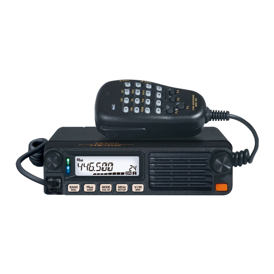
Yaesu FTM-7250DR Advance Manual
Vhf/uhf digital/analog transceiver c4fm/fm
Hide thumbs
Also See for FTM-7250DR:
- Operating manual (48 pages) ,
- Technical supplement (52 pages) ,
- Advance manual (42 pages)
Table of Contents
Advertisement
Advertisement
Table of Contents

Related Manuals for Yaesu FTM-7250DR


Summary of Contents for Yaesu FTM-7250DR
- Page 1 FTM-7250DR Advance Manual VHF/UHF DIGITAL/ANALOG TRANSCEIVER C4FM/FM...
-
Page 2: Table Of Contents
Contents Basic Operation ......................2 Microphone Gain Setting....................2 RF Squelch ........................2 Advanced Operation ...................... 3 Programming the Key Assignments ................3 Selecting the Squelch Type in the Analog FM Mode ............. 4 CTCSS Operation ......................5 Tone Search ........................6 DCS Operation ...................... -
Page 3: Basic Operation
Basic Operation Microphone Gain Setting The microphone gain has been programmed at the factory to a level that should be satisfactory for the supplied MH-48A6JA Microphone. If an after-market microphone is used, you may wish to set a different Mic Gain level. 1. -
Page 4: Advanced Operation
Advanced Operation Programming the Key Assignments Default FTM-7250DR key functions have been assigned to the Microphone [ P3 ] / [ P4 ] keys at the factory. The user may change these key function assignments, if quick access to another function is desired. -
Page 5: Selecting The Squelch Type In The Analog Fm Mode
(blinks) and when the tone signal disappears, the squelch opens and communication starts. Activates a new two-tone CTCSS pager function. When com- municating with FTM-7250DR transceivers among friends, PAGER (appears) specify personal codes (each code is composed of two tones) so that you can call only specific stations. -
Page 6: Ctcss Operation
Advanced Operation CTCSS Operation This radio is equipped with the CTCSS (Continuous Tone-coded Squelch System) that allows audio to be heard only when receiving signals containing a tone corresponding to the tone squelch menu setting. By matching the CTCSS tone with the partner station in advance, quiet standby monitoring is possible. -
Page 7: Tone Search
Advanced Operation Tone Search When the CTCSS tone being transmitted by another station is not known, you can tune the radio to the incoming signal and activate tone scan to search for and identify the tone being used. To scan for the tone in use: 1. -
Page 8: Dcs Operation
Advanced Operation DCS Operation This radio is equipped with a DCS (Digital Coded Squelch) function that allows audio to be heard only when signals containing the corresponding DCS code are received. By matching the DCS code with the partner stations beforehand, a quiet receive standby is possible.. -
Page 9: Dcs Search
Advanced Operation DCS Search When the DCS code being transmitted by another station is not known, you can tune the radio to the incoming signal and activate DCS code scan to search for and identify the DCS code being used. To scan for the DCS in use: 1. -
Page 10: Split Tone Operation
Advanced Operation Split Tone Operation The FTM-7250DR can be configured to operate in a “Split Tone” system via the Setup menu, to facilitate operation on repeaters using a mix of both CTCSS and DCS control. 1. Press and hold the [ MHz ( SETUP )] key to enter the Set mode. -
Page 11: Epcs (Enhanced Paging & Code Squelch) Operation
6. Press and hold the [ MHz ( SETUP )] key to lock in that tone and exit to normal operation. Note: The FTM-7250DR does not recognize the order of the 1st tone and the 2nd tone. In other words, for example, the FTM-7250DR considers both CTCSS pairs “05,... -
Page 12: Activating The Enhanced Paging & Code Squelch System
Advanced Operation Activating the Enhanced Paging & Code Squelch System 1. Press and hold the [ MHz ( SETUP )] key to enter the Set mode. 2. Rotate the DIAL knob to select “SQL TYPE 44”. 3. Press the [ MHz ( SETUP )] key, and then rotate the DIAL knob to select “PAGER”. - Page 13 Advanced Operation 3. Rotate the DIAL knob to select the desired num- ber of times (1-20 times or continuous) the Bell rings. Default: OFF à OFF à 1 TIME à 2 TIMES à à 20 TIMES à CONTINUE (continuous) à 4.
-
Page 14: Dtmf Operation
DTMF Operation DTMF tones (Dual Tone Multi Frequencies) are the tones you hear when dialing from a telephone keypad. The FTM-7250DR transceiver can transmit the DTMF codes by using the keys on the microphone or recalling registered number strings from memories. -
Page 15: Registering A Dtmf Code
Advanced Operation Registering a DTMF code 1. Press and hold the [ MHz ( SETUP )] key to enter the Set mode. 2. Rotate the DIAL knob to select “DT SET 18”. 3. Press the [ MHz ( SETUP )] key momentarily, then rotate the DIAL knob to select the desired memory channel (C0 to C9) to register the DTMF code. -
Page 16: Transmitting The Registered Dtmf Code
Advanced Operation Transmitting the registered DTMF code 1. Press and hold the [ MHz ( SETUP )] key to enter the Set mode. 2. Rotate the DIAL knob to select “DT AUTO 16”. 3. Press the [ MHz ( SETUP )] key momentarily, and then rotate the DIAL knob to select “AUTO”. -
Page 17: Setting Dtmf Autodialer Tx Delay Time
Advanced Operation Setting DTMF Autodialer TX delay time A longer delay may be set between the time the transmitter is keyed and the first DTMF digit is sent: 1. Press and hold the [ MHz ( SETUP )] key to enter the Set mode. -
Page 18: Memory Operation
Memory Operation Split Memory A separate transmit frequency may be registered to a memory channel to which a receive frequency has already been registered. 1. In the VFO mode, select the transmit frequency to be registered. 2. Press and hold the [ V/M ( MW )] key. A memory number will appear in the bottom right corner of the display. -
Page 19: Naming A Memory Channel
Memory Operation Naming a Memory Channel You may wish to append an alphanumeric “Tag” (label) to each memory, to aid in recollection of the channel’s use (such as club name, etc.). 1. Recall the memory channel on which you wish to append a label. 2. -
Page 20: Scanning
Scanning Scan Resume Options Select one of the three receiving operations to be performed after the scanning stops. (1) Restart scanning after receiving the frequency for the set amount of time. Select from 2.0 to 10.0 seconds (0.5 step). (2) Continue receiving the frequency until the signal disappears, and then restart scan- ning 2 seconds after the signal disappears (BUSY). -
Page 21: Memory Skip Scanning
Scanning Memory Skip Scanning When some memory channels are continuously active, you may wish to skip them during scanning, but still have them available for manual selection. To mask a memory to be skipped (only) during scanning, use the following procedure: 1. -
Page 22: Preferential Memory Scan
Scanning Preferential Memory Scan The FTM-7250DR also allows setting up a “Preferential Scan List” of channels, which you can “flag” within the memory system. The flagged channels are designated by an “ ” icon when they are selected, one by one, for the Preferential Scan List. -
Page 23: Programmable Memory Scan (Pms)
Scanning Programmable Memory Scan (PMS) The FTM-7250DR can be set to tune or scan only the frequencies between user-defined lower and band limits. Example: Set up a PMS channel by registering a lower frequency of 432.500 MHz, and an upper frequency of 432.800 MHz to the L1/U1 memory channels. -
Page 24: Band Edge Beeper
MH-48A6JA Microphone. Band Edge Beeper The FTM-7250DR will automatically “beep” when the receive band edge is encountered during scanning (either in standard VFO scanning or during PMS operation). Additionally, the band edge beep feature may be enabled to sound when the band edge frequency is reached while tuning the VFO, using the DIAL knob. -
Page 25: Priority Channel Scanning (Dual Watch)
The display will remain on the VFO, the selected memory channel, or the Home chan- nel, but every five seconds the FTM-7250DR will check the Priority Channel for activity. Note: During Dual Watch operation, the decimal points of the frequency display blink. -
Page 26: Gm Function
GM Function About the GM(Group Monitor) feature The GM (Group Monitor) function automatically checks to find if there are any stations with the GM function in operation with the same DG-ID number within communication range. Setting the receive DG-ID number to “00” will check for all the C4FM digital sta- tions In/Out of range. - Page 27 LCD. • Up to 24 stations may be displayed in order of their reception. Note: • The FTM-7250DR may not send its own location information because the FTM- 7250DR is not equipped with the GPS function.
-
Page 28: Gm Alert Beep
GM Function GM Alert Beep To alert you to the current status of GM operation, the GM (Group Monitor) feature allows two kinds of alert beeps (with the additional option of turning them off). Depending on your location and the potential annoyance associated with frequent beeps, you may choose the Beep mode which best suits your needs. -
Page 29: Clone
Clone The FTM-7250DR includes a convenient “Clone” feature, which allows the memory and configuration data from one transceiver to be transferred to another FTM-7250DR. This can be particularly useful when configuring a number of transceivers for a public service operation. -
Page 30: Setup (Menu) Mode
Setup (Menu) Mode The FTM-7250DR Setup (Menu) mode, already described in parts of many previous chapters, is easy to activate and setup. The Menus may be used to configure many of transceiver parameters, some of which have not been detailed previously. Use the following procedure to activate the Setup (Menu) mode: 1. - Page 31 Setup (Menu) Mode Menu Item Function Available Values Default Loading of the DTMF Autodialer Memo- DT SET ries. Setting of the DTMF Autodialer Sending DT SPEED 50/100 50 MS Speed. Enables/Disables the “Priority Channel DW RVRT ON/OFF Revert” feature. Enables/Disables the alert sound when GM RINGR detecting stations within communication IN RANGE/ALWAYS/OFF...
- Page 32 Setup (Menu) Mode Menu Item Function Available Values Default RX MODE Select the receive mode. AUTO/FM/AM AUTO SCAN RSM Selects the Scan Resume mode. BUSY/HOLD/2-10 (SEC) 5.0 SEC SCAN SKP Selects the Memory Scan mode. OFF/SKIP/SELECT SCNW MEM Set the memory scan frequency range. ALL/BAND SCNW VFO Set the VFO scan frequency range.
-
Page 33: Menu Selection Details
Menu Selection Details 1 APO Function: Enables/Disables the Automatic Power Off feature. Available Values: 0.5 H to 12.0 H (0.5 H/step) / OFF Default: OFF 2 BCLO Function: Enables/Disables the Busy Channel Lock-Out feature. Available Values: ON / OFF Default: OFF 3 BEP KEY Function: Enables/Disables the key beeper. -
Page 34: Dcs Code
Menu Selection Details 9 DC VOLT Function: Indicates the DC Supply Voltage. 10 DCS CODE Function: Setting of the DCS code. Available Values: 104 standard DCS codes Default: 023 DCS CODE 023 025 026 031 032 036 043 047 051 053 054 065 071 072 073 074 114 115 116 122 125 131 132 134 143 145 152 155 156 162 165 172 174 205 212 223 225 226 243 244 245 246 251 252 255 261 263 265 266 271 274 306 311 315 325 331 332 343 346 351... - Page 35 Menu Selection Details 14 DI POPUP Function: Sets the information pop-up time. Available Values: 2 SEC / 4 SEC / 6 SEC / 8 SEC / 10 SEC / 20 SEC / 30 SEC / 60 SEC / CONTINUE / OFF Default: 10 SEC 15 DPID LST Function: Registers the DP-ID of the other transceiver.
- Page 36 Menu Selection Details 22 GM INTVL Function: Selects the automatic GM beacon interval. Available Values: NORMAL / LONG Default: NORMAL 23 LCD DMMR Function: Setting of the front panel display’s illumination level. Available Values: LEVEL 1 - LEVEL 4 Default: LEVEL 4 24 LOCK Function: Selects the Control Locking Lockout combination.
- Page 37 Menu Selection Details 4. Repeat the previous step as necessary to complete the message (up to 8 characters). 5. To correct a mistake, press the [ BAND ( SQL )] key to backspace the cursor; now re-en- ter the correct letter/number. 6.
- Page 38 Menu Selection Details 35 RPT ARS Function: Activates/Deactivates the Automatic Repeater Shift feature.. Available Values: ON / OFF Default: ON 36 RPT FREQ Function: Sets the magnitude of the Repeater Shift. Available Values: 0.00 - 150.00 MHz Default: Depends on the transceiver version. 37 RPT SFT Function: Sets the Repeater Shift direction.
- Page 39 Menu Selection Details 41 SCNW MEM Function: Set the memory scan frequency range. Set the frequency band range while scanning in the memory mode. Available Values: ALL / BAND Default: ALL ALL: All the memory channels are scanned without regard to the band of the registered frequency of the memory channels.
- Page 40 Menu Selection Details 45 STEP Function: Sets the frequency synthesizer steps. Available Values: AUTO / 5 / 6.25 / 8.33* / 10 / 12.5 / 15 / 20 / 25 / 50 / 100 (kHz) Default: AUTO *: AIR Band 46 TEMP Function: Indicates the final transistor &...
-
Page 41: Vfo Mode
Menu Selection Details 52 VFO MODE Function: Set the frequency setting range in the VFO mode by DIAL knob. Available Values: ALL / BAND Default: BAND ALL: Tuning continues to the next band when reaching the end of a band. BAND: Tuning continues to the other end of the current band when reaching the end of the band. - Page 42 Copyright 2018 YAESU MUSEN CO., LTD. All rights reserved. No portion of this manual may be reproduced without the permission of YAESU MUSEN CO., LTD. YAESU MUSEN CO., LTD. Tennozu Parkside Building 2-5-8 Higashi-Shinagawa, Shinagawa-ku, Tokyo 140-0002 Japan YAESU USA 6125 Phyllis Drive, Cypress, CA 90630, U.S.A.