Table of Contents
Advertisement
Advertisement
Table of Contents

Related Manuals for Lenovo ThinkSystem ST550 7X09


Summary of Contents for Lenovo ThinkSystem ST550 7X09
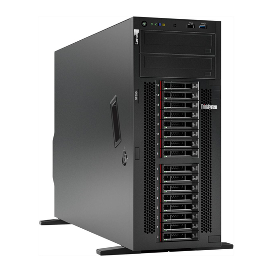
- Page 1 ThinkSystem ST550 Maintenance Manual Machine Types: 7X09 and 7X10...
- Page 2 Before using this information and the product it supports, be sure to read and understand the safety information and the safety instructions, which are available at: http://thinksystem.lenovofiles.com/help/topic/safety_documentation/pdf_files.html In addition, ensure that you are familiar with the terms and conditions of the Lenovo warranty for your server, which can be found at: http://datacentersupport.lenovo.com/warrantylookup Third Edition (March 2018) ©...
-
Page 3: Table Of Contents
Install the backplane for eight 2.5-inch hot- Rack latch replacement... . swap drives ....103 © Copyright Lenovo 2017, 2018... - Page 4 Remove the backplane for four 3.5-inch hot-swap Install a processor and heat sink ..163 drives ....104 System board replacement ..168 Install the backplane for four 3.5-inch hot- Remove the system board .
-
Page 5: Safety
Vor der Installation dieses Produkts die Sicherheitshinweise lesen. Prima di installare questo prodotto, leggere le Informazioni sulla Sicurezza. Les sikkerhetsinformasjonen (Safety Information) før du installerer dette produktet. Antes de instalar este produto, leia as Informações sobre Segurança. © Copyright Lenovo 2017, 2018... -
Page 6: Safety Inspection Checklist
Click the Power tab to see all line cords. • Make sure that the insulation is not frayed or worn. 3. Check for any obvious non-Lenovo alterations. Use good judgment as to the safety of any non-Lenovo alterations. ThinkSystem ST550 Maintenance Manual... - Page 7 5. Check for worn, frayed, or pinched cables. 6. Make sure that the power-supply cover fasteners (screws or rivets) have not been removed or tampered with. © Copyright Lenovo 2017, 2018...
- Page 8 ThinkSystem ST550 Maintenance Manual...
-
Page 9: Chapter 1. Introduction
Identifying your server When you contact Lenovo for help, the machine type and serial number information helps support technicians to identify your server and provide faster service. The machine type and serial number are on the ID label on the front of the server. -
Page 10: Server Form Factor
Scan the QR code with a mobile device and a QR code reader application to get quick access to the Lenovo Service web site for this server. The Lenovo Service web site provides additional information for parts installation and replacement videos, and error codes for server support. -
Page 11: Specifications
• Up to two Intel Xeon processors • Designed for Land Grid Array (LGA) 3647 socket For a list of supported processors, see: http://www.lenovo.com/us/en/serverproven/ DIMM • Minimum: 8 GB • Maximum: – 384 GB using registered DIMMs (RDIMMs) – 768 GB using load-reduced DIMMs (LRDIMMs) •... - Page 12 • Supports (depending on the model): – 8 GB, 16 GB, and 32 GB RDIMMs – 64 GB LRDIMMs Note: For a list of supported DIMMs, see: http://www.lenovo.com/us/en/serverproven/ Supported drives The drives supported by your server vary by model. • Storage drive...
- Page 13 – PCIe slot 6: PCIe x8 (x4, x1), full-height, full-length • For processor 2 – PCIe slot 4: PCIe x16 (x8, x4, x1), full-height, full-length – PCIe slot 5: PCIe x16 (x16, x8, x4, x1), full-height, full-length, double-width The following RAID adapters can be installed in an appropriate PCIe slot. •...
- Page 14 System fans • One processor: two fans (fan 1 and 2) or three fans (fan 1, 2, and 4) • Two processors: three fans (fan 1, 2, and 3) or four fans (fan 1, 2, 3, and 4) Notes: • Fan 3 is required if the expansion drive cage is installed. •...
-
Page 15: Firmware Updates
Note: Lenovo typically releases firmware in bundles called UpdateXpress System Packs (UXSPs). To ensure that all of the firmware updates are compatible, you should update all firmware at the same time. If you are updating firmware for both the Lenovo XClarity Controller and UEFI, update the firmware for Lenovo XClarity Controller first. - Page 16 Machine-type-specific firmware-only UXSPs are also available. See the following table to determine the best Lenovo tool to use for installing and setting up the firmware: Note: The server UEFI settings for option ROM must be set to Auto or UEFI to update firmware using Lenovo XClarity Administrator or Lenovo XClarity Essentials.
- Page 17 Additional information about using Lenovo XClarity Provisioning Manager to update firmware is available http://sysmgt.lenovofiles.com/help/topic/LXPM/platform_update.html • Lenovo XClarity Controller If you need to install a specific update, you can use the Lenovo XClarity Controller interface for a specific server. Notes: – To perform an in-band update through Windows or Linux, the operating system driver must be installed and the Ethernet-over-USB (sometimes called LAN over USB) interface must be enabled.
-
Page 18: Configuring The Lan Over Usb Interface Manually
Lenovo XClarity Essentials OneCLI is a collection of command line applications that can be used to manage Lenovo servers.Its update application can be used to update firmware and device drivers for your servers. The update can be performed within the host operating system of the server (in-band) or remotely through the BMC of the server (out-of-band). -
Page 19: Tech Tips
Tech Tips Lenovo continually updates the support website with the latest tips and techniques that you can use to solve issues that you might have with your server. These Tech Tips (also called retain tips or service bulletins) provide procedures to work around issues related to the operation of your server. -
Page 20: Power On The Server
Power off the server The server remains in a standby state when it is connected to a power source, allowing the Lenovo XClarity Controller to respond to remote power-on requests. To remove all power from the server (power-on LED off), you must disconnect all power cables. -
Page 21: Chapter 2. Server Components
Drive activity LED (green) Foot stands Drive status LED (yellow) 3.5-inch drive bays 0–3 3.5-inch drive bays 4–7 2.5-inch drive bays 0–7 2.5-inch drive bays 8–15 Optical-drive status LED Optical-drive eject/close button Optical-drive manual-eject hole © Copyright Lenovo 2017, 2018... - Page 22 Front panel For information about the controls, connectors, and status LEDs on the front panel, see “Front panel” on page 16. Optical-drive bay 2 The 5.25-inch optical-drive bay 2 is for a secondary optical drive or a tape drive. Some models have a secondary optical drive or a tape drive installed.
- Page 23 Optical-drive eject/close button Press this button to eject or close the optical drive when the server power is on. Optical-drive manual-eject hole Insert a straightened paper clip into the optical-drive manual-eject hole to eject the disc tray when the eject/ close button does not work.
-
Page 24: Front Panel
For some server models, your server comes with an expansion drive cage. You can install up to four 2.5-inch SAS/SATA drives to the cage. Drive activity LED Drive status LED Each hot-swap drive has two LEDs. Drive LED Status Description Drive activity LED (left) Solid green The drive is powered but not active. - Page 25 Each time you press the system ID button, the state of both the system ID LEDs changes. The LEDs can be changed to on, blinking, or off. You can also use the Lenovo XClarity...
-
Page 26: Rear View
Controller or a remote management program to change the state of the system ID LEDs to assist in visually locating the server among other servers. If the XClarity Controller USB connector is set to have both the USB 2.0 function and XClarity Controller management function, you can press the system ID button for three seconds to switch between the two functions. - Page 27 Rear view of server models with a fixed power supply Figure 7. Rear view of server models with a fixed power supply Table 4. Components on the rear of server models with a fixed power supply Callout Callout Fixed power supply USB 2.0 connectors (2) USB 3.0 connectors (2) XClarity Controller network connector...
- Page 28 VGA connector Used to attach a VGA-compatible video device, such as a VGA monitor. NMI button Press this button to force a nonmaskable interrupt (NMI) to the processor. By this way, you can blue screen the server and take a memory dump. You might have to use a pen or the end of a straightened paper clip to press the button.
-
Page 29: Rear View Leds
The hot-swap redundant power supplies help you avoid significant interruption to the operation of the system when a power supply fails. You can purchase a power supply option from Lenovo and install the power supply to provide power redundancy without turning off the server. - Page 30 Each time you press the system ID button, the state of both the system ID LEDs changes. The LEDs can be changed to on, blinking, or off. You can also use the Lenovo XClarity Controller or a remote management program to change the state of the system ID LEDs to assist in visually locating the server among other servers.
- Page 31 Description Power input LED • Off: The power supply is disconnected from the ac power source or a power problem occurs. • Green: The power supply is connected to the ac power source. Power output LED • Green: The server is on and the power supply is working normally. •...
-
Page 32: System Board Components
System board components The illustration in this section shows the component locations on the system board. Figure 10. System board components Table 7. Components on the system board Callout Callout CPU 2 power connector Processor 2 socket Main power connector DIMM slots (12) Backplane 1 power connector Backplane 2 power connector... -
Page 33: System Board Jumpers
Table 7. Components on the system board (continued) Callout Callout Intrusion switch connector /TPM connector (for China only) PCIe slot 6 (for processor 1) PCIe slot 5 (for processor 2) PCIe slot 4 (for processor 2) PCIe slot 3 (for processor 1) PCIe slot 2 (for processor 1) PCIe slot 1 (for processor 1) System fan 4 connector... - Page 34 Jumper setting JP16 • Pins 1 and 2: The jumper is in default setting. Force XCC update jumper • Pins 2 and 3: Force the Lenovo XClarity Controller to update to the latest version. Force XCC reset jumper JP19 • Pins 1 and 2: The jumper is in default setting.
-
Page 35: Internal Cable Routing
Internal cable routing Some of the components in the server have internal cables and cable connectors. To connect cables, observe the following guidelines: • Turn off the server before you connect or disconnect any internal cables. • See the documentation that comes with any external devices for additional cabling instructions. It might be easier for you to route cables before you connect the devices to the server. - Page 36 ThinkSystem ST550 Maintenance Manual...
-
Page 37: Front Panel
Front panel Use the section to understand the cable routing for the front panel. Note: Ensure that all cables are routed through the correct cable clips. Figure 12. Cable routing for the front panel Cable Operator-information-panel cable Operator-information-panel connector on the system board USB cable Front-panel-USB connector on the system board... -
Page 38: Optical Drive
Optical drive Use the section to understand the cable routing for the optical drives. Note: Ensure that all cables are routed through the correct cable clips. Figure 13. Cable routing for the optical drives Cable From Signal cable Signal connector on the optical drive 1 Optical-drive-1 signal connector on the system board Signal cable... -
Page 39: Tape Drive
Tape drive Use the section to understand the cable routing for the tape drive. SAS tape drive Note: Ensure that all cables are routed through the correct cable clips. Figure 14. Cable routing for the SAS tape drive Cable From Signal cable Signal connector on the tape drive An available connector on the RAID adapter... - Page 40 USB tape drive Note: Ensure that all cables are routed through the correct cable clips. Figure 15. Cable routing for the USB tape drive From Cable Signal cable Signal connector on the tape drive Internal USB 3.0 connector on the system board Power cable Power connector on the tape drive...
-
Page 41: Power Interface Board
Power interface board Use the section to understand the cable routing for the power interface board. Note: Ensure that all cables are routed through the correct cable clips. Figure 16. Cable routing for the power interface board Cable From Signal cable Signal connector on the power interface Power-interface-board signal connector on board... -
Page 42: Fixed Power Supply
Fixed power supply Use the section to understand the cable routing for the fixed power supply. Note: Ensure that all cables are routed through the correct cable clips. Figure 17. Cable routing for the fixed power supply Cable CPU 1 power cable CPU 1 power connector on the system board Main power cable Main power connector on the system board... -
Page 43: Graphics Adapter
Graphics adapter Use the section to understand the cable routing for the graphics adapters. Note: Ensure that all cables are routed through the correct cable clips. Figure 18. Cable routing for the graphics adapters Cable From Power cable Power connector on one graphics adapter GPU 1 connector on the power interface board Power cable... -
Page 44: Simple-Swap-Drive Backplate
Simple-swap-drive backplate Use the section to understand the cable routing for the simple-swap-drive backplate. This topic contains the following information: • “Server models with four 3.5-inch simple-swap drives” on page 36 • “Server models with eight 3.5-inch simple-swap drives” on page 37 Server models with four 3.5-inch simple-swap drives Use this section to understand the cable routing for server models with four 3.5-inch simple-swap drives. - Page 45 Server models with eight 3.5-inch simple-swap drives Use this section to understand the cable routing for server models with eight 3.5-inch simple-swap drives. Note: Ensure that all cables are routed through the correct cable clips. Figure 20. Cable routing for server models with eight 3.5-inch simple-swap drives From Signal cable on backplate 1 SAS 0–3 connector on the system board...
-
Page 46: Hot-Swap-Drive Backplane
Hot-swap-drive backplane Use the section to understand the cable routing for hot-swap-drive backplanes. This topic contains the following information: • “Server models with eight 2.5-inch hot-swap drives” on page 39 • “Server models with sixteen 2.5-inch hot-swap drives” on page 41 •... - Page 47 Server models with eight 2.5-inch hot-swap drives Use this section to understand the cable routing for server models with eight 2.5-inch hot-swap drives. Server model: eight 2.5-inch SAS/SATA drives, one 8i RAID adapter Notes: • Ensure that all cables are routed through the correct cable clips. •...
- Page 48 Server model: four 2.5-inch SAS/SATA drives, four 2.5-inch SAS/SATA/NVMe drives, one 8i RAID adapter, one NVMe adapter Notes: • Ensure that all cables are routed through the correct cable clips. • Broken lines indicate the hidden parts. Figure 22. Cable routing for server models with four 2.5-inch SAS/SATA drives, four 2.5-inch SAS/SATA/NVMe drives, one 8i RAID adapter, and one NVMe adapter Cable From...
- Page 49 Server models with sixteen 2.5-inch hot-swap drives Use this section to understand the cable routing for server models with sixteen 2.5-inch hot-swap drives. Server model: sixteen 2.5-inch SAS/SATA drives, two 8i RAID adapters Notes: • Ensure that all cables are routed through the correct cable clips. •...
- Page 50 Server model: sixteen 2.5-inch SAS/SATA drives, one 16i RAID adapter Notes: • Ensure that all cables are routed through the correct cable clips. • Broken lines indicate the hidden parts. Figure 24. Cable routing for server models with sixteen 2.5-inch SAS/SATA drives and one 16i RAID adapter From Cable SAS signal cable for...
- Page 51 Server model: twelve 2.5-inch SAS/SATA drives, four 2.5-inch SAS/SATA/NVMe drives, one 16i RAID adapter, one NVMe adapter Notes: • Ensure that all cables are routed through the correct cable clips. • Broken lines indicate the hidden parts. Figure 25. Cable routing for server models with twelve 2.5-inch SAS/SATA drives, four 2.5-inch SAS/SATA/NVMe drives, one 16i RAID adapter, and one NVMe adapter From Cable...
- Page 52 Server models with twenty 2.5-inch hot-swap drives Use this section to understand the cable routing for server models with twenty 2.5-inch hot-swap drives. Server model: twenty 2.5-inch SAS/SATA drives, one 24i RAID adapter Notes: • Ensure that all cables are routed through the correct cable clips. •...
- Page 53 Cable From SAS signal cable for SAS connector on backplane 3 C4 connector on the 24i RAID adapter backplane 3 Power cable for backplane 2 Power connector on backplane 2 Backplane 2 power connector on the system board Power cable for backplane 3 Power connector on backplane 3 Backplane 3 power connector on the system board...
- Page 54 Server model: sixteen 2.5-inch SAS/SATA drives, four 2.5-inch SAS/SATA/NVMe drives, one 24i RAID adapter, one NVMe adapter Notes: • Ensure that all cables are routed through the correct cable clips. • Broken lines indicate the hidden parts. Figure 27. Cable routing for server models with sixteen 2.5-inch SAS/SATA drives, four 2.5-inch SAS/SATA/NVMe drives, one 24i RAID adapter, and one NVMe adapter Cable From...
- Page 55 Cable From SAS signal cable for SAS 0 and SAS 1 connectors on C2 and C3 connectors on the 24i RAID backplane 2 backplane 2 adapter SAS signal cable for SAS connector on backplane 3 C4 connector on the 24i RAID adapter backplane 3 Power cable for backplane 3 Power connector on backplane 3...
- Page 56 Server models with four 3.5-inch hot-swap drives Use this section to understand the cable routing for server models with four 3.5-inch hot-swap SAS/SATA drives. Server model: four 3.5-inch SAS/SATA drives, one 8i RAID adapter Notes: • Ensure that all cables are routed through the correct cable clips. •...
- Page 57 Server models with eight 3.5-inch hot-swap drives Use this section to understand the cable routing for server models with eight 3.5-inch hot-swap SAS/SATA drives. Server model: eight 3.5-inch SAS/SATA drives, one 8i RAID adapter Notes: • Ensure that all cables are routed through the correct cable clips. •...
- Page 58 Server models with eight 3.5-inch hot-swap drives and four 2.5-inch hot-swap drives Use this section to understand the cable routing for server models with eight 3.5-inch hot-swap SAS/SATA drives and four 2.5-inch hot-swap SAS/SATA drives. Server model: eight 3.5-inch hot-swap SAS/SATA drives, four 2.5-inch hot-swap SAS/SATA drives, two 8i RAID adapters Notes: •...
- Page 59 Cable From SAS signal cable for SAS connector on backplane 1 C0 connector on one 8i RAID adapter backplane 1 SAS signal cable for SAS connector on backplane 2 C1 connector on one 8i RAID adapter backplane 2 Power cable for backplane 1 Power connector on backplane 1 Backplane 1 power connector on the system board...
- Page 60 Server model: eight 3.5-inch hot-swap SAS/SATA drives, four 2.5-inch hot-swap SAS/SATA drives, one 16i RAID adapter Notes: • Ensure that all cables are routed through the correct cable clips. • Broken lines indicate the hidden parts. Figure 31. Cable routing for server models with eight 3.5-inch hot-swap SAS/SATA drives, four 2.5-inch hot-swap SAS/ SATA drives, and one 16i RAID adapter Cable From...
- Page 61 Cable From Power cable for backplane 1 Power connector on backplane 1 Backplane 1 power connector on the system board Power cable for backplane 2 Power connector on backplane 2 Backplane 2 power connector on the system board SAS signal cable for SAS connector on backplane 3 C2 connector on the 16i RAID adapter backplane 3...
-
Page 62: Parts List
Use the parts list to identify each of the components that are available for your server. For more information about ordering the parts shown in Figure 32 “Server components” on page 55: http://datacentersupport.lenovo.com/us/en/products/servers/thinksystem/st550/7x09/parts Note: Depending on the model, your server might look slightly different from the illustration. - Page 63 Tier 1 CRU at your request with no service agreement, you will be charged for the installation. • Tier 2 customer replaceable unit: You may install a Tier 2 CRU yourself or request Lenovo to install it, at no additional charge, under the type of warranty service that is designated for your server.
- Page 64 • Consumable and Structural parts: Purchase and replacement of consumable and structural parts is your responsibility. If Lenovo acquires or installs a structural component at your request, you will be charged for the service. Table 9. Parts listing Consumable Description...
- Page 65 Table 9. Parts listing (continued) Consumable Description Index Tier 1 CRU Tier 2 CRU Structural parts M.2 drive √ TCM/TPM adapter (only available in √ China) Heat sink √ System board √ √ DIMM √ PCIe adapter √ Serial port module √...
-
Page 66: Power Cords
Several power cords are available, depending on the country and region where the server is installed. To view the power cords that are available for the server: 1. Go to: http://dcsc.lenovo.com/#/ 2. Click Preconfigured Model or Configure to order. 3. Enter the machine type and model for your server to display the configurator page. -
Page 67: Chapter 3. Hardware Replacement Procedures
– To avoid straining the muscles in your back, lift by standing or by pushing up with your leg muscles. • Make sure that you have an adequate number of properly grounded electrical outlets for the server, monitor, and other devices. © Copyright Lenovo 2017, 2018... -
Page 68: System Reliability Guidelines
• Back up all important data before you make changes related to the disk drives. • Have a small flat-blade screwdriver, a small Phillips screwdriver, and a T8 torx screwdriver available. • You do not have to turn off the server to remove or install hot-swap power supplies or hot-plug USB devices. -
Page 69: Front Door Replacement
Attention: Prevent exposure to static electricity, which might lead to system halt and loss of data, by keeping static-sensitive components in their static-protective packages until installation, and handling these devices with an electrostatic-discharge wrist strap or other grounding system. • Limit your movement to prevent building up static electricity around you. •... -
Page 70: Install The Front Door
Figure 33. Front door removal Step 1. Open the front door. Step 2. Lift the front door slightly upward until you can completely remove it. Install the front door Use this information to install the front door. “Read the installation Guidelines”... -
Page 71: Foot Stands Replacement
Figure 34. Front door installation Step 1. Align the two hooks on the front door with the corresponding holes in the front bezel. Then, move the front door inward and then pull it slightly downward until it is secured in place by the hooks. Step 2. -
Page 72: Install The Foot Stands
Step 2. For each foot stand, press the release tab and then pivot the foot stand outward to remove it from the chassis. Figure 35. Foot stand removal Install the foot stands Use this information to install the foot stands. “Read the installation Guidelines”... -
Page 73: Rack Latch Replacement
Step 2. For each foot stand, carefully insert the two tabs on the foot stand into the corresponding holes in the chassis. Then, pivot the foot stand inward until the other side clicks into place. Figure 36. Foot stand installation Important: To help the server stand steadily, ensure that the foot stands are installed outward as shown in “Front view”... -
Page 74: Install A Rack Latch
Figure 37. Rack latch removal Step 1. Remove the screws that secure the rack latch. Step 2. Pivot the rack latch as shown until the rack latch is disengaged from the chassis. Then, remove the rack latch from the chassis. If you are instructed to return the old rack latch, follow all packaging instructions and use any packaging materials that are provided. -
Page 75: Server Cover Replacement
Figure 38. Rack latch installation Step 1. Insert the rack latch tab into the hole in the chassis as shown. Then, align the holes in the rack latch with the corresponding holes in the chassis underside. Step 2. Install the screws to secure the rack latch. After installing the rack latch, reinstall the server to the rack. -
Page 76: Remove The Server Cover
CAUTION: Hazardous voltage, current, and energy levels might be present. Only a qualified service technician is authorized to remove the covers where the following label is attached. Remove the server cover Use this information to remove the server cover. “Read the “Power off “ATTENTION: installation... - Page 77 “Read the “Power off “ATTENTION: installation the server Static Sensitive Device Guidelines” on for this task” Ground package before opening” page 59 on page 12 on page 60 Before installing the server cover: 1. Ensure that all adapters and other components are installed and seated correctly and that you have not left loose tools or parts inside the server.
-
Page 78: Raid Super Capacitor Module Replacement
Note: This topic applies only to server models that have RAID super capacitor modules installed. The RAID super capacitor module protects the cache memory on the installed RAID adapter. You can purchase a RAID super capacitor module from Lenovo. For a list of supported options, see: http://www.lenovo.com/us/en/serverproven/... -
Page 79: Install A Raid Super Capacitor Module
If you are instructed to return the old RAID super capacitor module, follow all packaging instructions and use any packaging materials that are provided. Install a RAID super capacitor module Use this information to install a RAID super capacitor module on the air baffle. “Read the “Power off “ATTENTION:... -
Page 80: Remove The Air Baffle
CAUTION: Hazardous energy present. Voltages with hazardous energy might cause heating when shorted with metal, which might result in spattered metal, burns, or both. S017 CAUTION: Hazardous moving fan blades nearby. Remove the air baffle Use this information to remove the air baffle. “Read the “Power off installation... -
Page 81: Install The Air Baffle
Figure 43. Air baffle removal Attention: For proper cooling and airflow, install the air baffle before you turn on the server. Operating the server with the air baffle removed might damage server components. Install the air baffle Use this information to install the air baffle. “Read the “Power off installation... -
Page 82: Front Fan Replacement
Figure 44. Air baffle installation Step 1. Carefully insert the rear end of the air baffle into the chassis. Step 2. Press the front end of the air baffle downward until it snaps into place. After installing the air baffle: 1. -
Page 83: Remove A Front Fan
CAUTION: To avoid personal injury, disconnect the fan cables before removing the fan from the device. S002 CAUTION: Make sure all power cords are disconnected from system when reading in this manual and the following step is required to complete: Disconnect the power cords and all external cables from the rear of the enclosure. -
Page 84: Install A Front Fan
Step 2. Press down the release tab and pivot the front fan as shown. Then, take the front fan out of the chassis. Figure 45. Front fan removal After removing the front fan: 1. Install either a new front fan or a fan filler for proper air flow. See “Install a front fan” on page 76. 2. -
Page 85: Rear Fan Replacement
Step 2. Align the pins on the front fan with the corresponding holes in the chassis. Then, pivot the front fan forward until it snaps into place. Figure 46. Front fan installation Step 3. Connect the front fan cable to the corresponding fan connector on the system board. For the location of the system fan connectors, see “System board components”... -
Page 86: Remove The Rear Fan
S002 CAUTION: Make sure all power cords are disconnected from system when reading in this manual and the following step is required to complete: Disconnect the power cords and all external cables from the rear of the enclosure. Remove the rear fan Use this information to remove the rear fan. -
Page 87: Install The Rear Fan
After removing the rear fan: 1. Install a new rear fan to replace the old one. See “Install the rear fan” on page 79. 2. If you are instructed to return the old rear fan, follow all packaging instructions and use any packaging materials that are provided. -
Page 88: Pcie Adapter Holder Replacement
PCIe adapter holder replacement Use this information to remove and install the PCIe adapter holder, which helps to hold the full-length PCIe adapters. Remove the PCIe adapter holder Use this information to remove the PCIe adapter holder. “Read the “Power off installation the server Guidelines”... -
Page 89: Front Bezel Replacement
“Read the “Power off installation the server Guidelines” on for this task” page 59 on page 12 To install the PCIe adapter holder, complete the following steps: Figure 50. PCIe adapter holder installation Step 1. Insert the PCIe-adapter-holder post into the corresponding recess in the chassis. Step 2. -
Page 90: Install The Front Bezel
Before removing the front bezel: 1. If the server is installed in a rack, remove the server from the rack. Then, remove the rack latches. See “Remove a rack latch” on page 65. 2. If your server has the front door installed, remove the front door. See “Remove the front door” on page 3. -
Page 91: Front Panel Replacement
Figure 52. Front bezel installation Step 1. Align the three plastic tabs with the corresponding holes in the chassis. Then, pivot the front bezel inward until it snaps into place. After installing the front bezel, complete the parts replacement. See “Complete the parts replacement” on page 178. -
Page 92: Install The Front Panel
Step 2. Press the release tab in the direction as shown and then pull the front panel out of the dedicated bay. Figure 53. Front panel removal Step 3. Take the front panel out of the chassis. Note: Adjust any cables that might impede your operation. If you are instructed to return the old front panel, follow all packaging instructions and use any packaging materials that are provided. -
Page 93: Optical Drive Or Tape Drive Replacement
Step 2. Insert the front panel into the dedicated bay as shown. Then, carefully slide the front panel into the bay until it snaps into place. Figure 54. Front panel installation Step 3. Carefully route the two front panel cables from the secured front panel along the back side of the storage drive bays. -
Page 94: Remove An Optical Drive Or A Tape Drive
S007 CAUTION: This product contains a Class 1M laser. Do not view directly with optical instruments. S008 DANGER Some laser products contain an embedded Class 3A or Class 3B laser diode. Note the following. Laser radiation when open. Do not stare into the beam, do not view directly with optical instruments, and avoid direct exposure to the beam. - Page 95 Step 2. Press and hold the release tab and push the optical drive or the tape drive forward to remove it from the chassis. Figure 55. Optical drive removal After removing an optical drive or a tape drive: 1. Install a new optical drive or tape drive, or install a filler to cover the drive bay. To install a new optical drive or a tape drive, see “Install an optical drive or a tape drive”...
-
Page 96: Install An Optical Drive Or A Tape Drive
b. Install the cover of the drive bay filler to the front bezel. Then, install the front bezel to the chassis. Figure 57. Drive-bay-filler cover installation 2. Remove the retainer from the removed optical drive or tape drive, and then install the retainer to the chassis. - Page 97 Before installing an optical drive or a tape drive: 1. If the drive bay is covered by a filler, remove it first. Store the filler in case that you later remove the optical drive or the tape drive and need the filler to cover the place. To remove the filler, complete the following steps: a.
- Page 98 Step 1. Remove the retainer from the chassis. Figure 61. Drive retainer removal Step 2. Install the retainer on only the left side of the optical drive or tape drive. Figure 62. Optical drive retainer installation Step 3. Hold the optical drive or tape drive in correct orientation and then slide it into the drive bay until it snaps into position.
-
Page 99: Simple-Swap Drive Replacement
After installing the optical drive or tape drive, complete the parts replacement. See “Complete the parts replacement” on page 178. Simple-swap drive replacement Use this information to remove and install a simple-swap drive. Notes: • This section applies only to server models that support simple-swap drives. •... - Page 100 Step 1. Use a screwdriver to turn the handle lock to the unlocked position. Then, the tray handle opens automatically. Figure 64. Opening the tray handle of a 3.5-inch simple-swap drive Step 2. Pull the tray handle and carefully slide the simple-swap drive out of the drive bay. Figure 65.
-
Page 101: Install A Simple-Swap Drive
• For a complete list of supported optional devices for the server, see: http://www.lenovo.com/us/en/serverproven/ • The drive bays are numbered to indicate the installation order (starting from number “0”). Follow the installation order when you install a drive. See “Front view” on page 13. - Page 102 None The simple-swap drive is not active. 4. If the server has the front door installed, close it. 5. Use the Lenovo XClarity Provisioning Manager to configure the RAID if necessary. For more information, see: http://sysmgt.lenovofiles.com/help/topic/LXPM/RAID_setup.html ThinkSystem ST550 Maintenance Manual...
-
Page 103: Hot-Swap Drive Replacement
Hot-swap drive replacement Use this information to remove and install a hot-swap drive. You can remove or install a hot-swap drive without turning off the server, which helps you avoid significant interruption to the operation of the system. Notes: • This section applies only to server models that support hot-swap drives. •... -
Page 104: Install A Hot-Swap Drive
• Depending on your server models, your server supports the following drive types: – NVMe SSD – SAS/SATA SSD – SAS/SATA HDD For a complete list of supported optional devices for the server, see: http://www.lenovo.com/us/en/serverproven/ ThinkSystem ST550 Maintenance Manual... - Page 105 • The drive bays are numbered to indicate the installation order (starting from number “0”). Follow the installation order when you install a drive. See “Front view” on page 13. • You can mix drives of different types, different sizes, and different capacities in one system, but not in one RAID array.
-
Page 106: Simple-Swap-Drive Backplate Replacement
1. Continue to install additional hot-swap drives if necessary. 2. Complete the parts replacement. See “Complete the parts replacement” on page 178. 3. Close the front door. 4. Use the Lenovo XClarity Provisioning Manager to configure the RAID if necessary. For more information, see: http://sysmgt.lenovofiles.com/help/topic/LXPM/RAID_setup.html Simple-swap-drive backplate replacement Use this information to remove and install a simple-swap-drive backplate. -
Page 107: Remove A Simple-Swap-Drive Backplate
Note: This section applies only to server models that have simple-swap-drive backplates installed. Remove a simple-swap-drive backplate Use this information to remove a simple-swap-drive backplate. “Read the “Power off “ATTENTION: installation the server Static Sensitive Device Guidelines” on for this task” Ground package before opening”... -
Page 108: Hot-Swap-Drive Backplane Replacement
“Read the “Power off “ATTENTION: installation the server Static Sensitive Device Guidelines” on for this task” Ground package before opening” page 59 on page 12 on page 60 Before installing the simple-swap-drive backplate, touch the static-protective package that contains the new backplate to any unpainted surface on the outside of the server. -
Page 109: Remove The Backplane For Four 2.5-Inch Hot-Swap Drives
• “Remove the backplane for four 3.5-inch hot-swap drives” on page 104 • “Install the backplane for four 3.5-inch hot-swap drives” on page 105 Remove the backplane for four 2.5-inch hot-swap drives Use this information to remove the backplane for four 2.5-inch hot-swap drives. “Read the “Power off “ATTENTION:... -
Page 110: Install The Backplane For Four 2.5-Inch Hot-Swap Drives
Install the backplane for four 2.5-inch hot-swap drives Use this information to install the backplane for four 2.5-inch hot-swap drives. “Read the “Power off “ATTENTION: installation the server Static Sensitive Device Guidelines” on for this task” Ground package before opening” page 59 on page 12 on page 60... -
Page 111: Install The Backplane For Eight 2.5-Inch Hot-Swap Drives
“Read the “Power off “ATTENTION: installation the server Static Sensitive Device Guidelines” on for this task” Ground package before opening” page 59 on page 12 on page 60 Before removing the backplane for eight 2.5-inch hot-swap drives: 1. Remove the server cover. See “Remove the server cover” on page 68. 2. -
Page 112: Remove The Backplane For Four 3.5-Inch Hot-Swap Drives
“Read the “Power off “ATTENTION: installation the server Static Sensitive Device Guidelines” on for this task” Ground package before opening” page 59 on page 12 on page 60 Before installing the backplane for eight 2.5-inch hot-swap drives, touch the static-protective package that contains the new backplane to any unpainted surface on the outside of the server. -
Page 113: Install The Backplane For Four 3.5-Inch Hot-Swap Drives
Before removing the backplane for four 3.5-inch hot-swap drives: 1. Remove the server cover. See “Remove the server cover” on page 68. 2. Remove the air baffle. See “Remove the air baffle” on page 72. 3. Remove the front fans. See “Remove a front fan” on page 75. 4. -
Page 114: Expansion Drive Cage Replacement
“Read the “Power off “ATTENTION: installation the server Static Sensitive Device Guidelines” on for this task” Ground package before opening” page 59 on page 12 on page 60 Before installing the backplane for four 3.5-inch hot-swap drives, touch the static-protective package that contains the new backplane to any unpainted surface on the outside of the server. -
Page 115: Remove The Expansion Drive Cage
Note: This section applies only server models that have the expansion drive cage installed. Remove the expansion drive cage Use this information to remove the expansion drive cage. “Read the “Power off “ATTENTION: installation the server Static Sensitive Device Guidelines” on for this task”... -
Page 116: Install The Expansion Drive Cage
After removing the expansion drive cage: 1. Depending on your needs, you can install a new expansion drive cage, a filler, an optical drive, or a tape drive to cover the bay for proper air flow. 2. If you are instructed to return the old expansion drive cage, follow all packaging instructions and use any packaging materials that are provided. -
Page 117: Dimm Replacement
After installing the expansion drive cage: 1. Ensure that the signal cables are secured by the clips and are bound correctly by the Velcro strap. Figure 82. Securing and binding the signal cables correctly 2. Complete the parts replacement. See “Complete the parts replacement” on page 178. DIMM replacement Use this information to remove and install a DIMM. -
Page 118: Dimm Installation Rules
– Always wear an electrostatic-discharge strap when removing or installing DIMMs. Electrostatic- discharge gloves can also be used. – Never hold two or more DIMMs together so that they touch. Do not stack DIMMs directly on top of each other during storage. –... - Page 119 – 768 GB using LRDIMMs (two processors installed and one 64 GB LRDIMM installed in each of the 12 DIMM slots) For a list of supported DIMM options, see: http://www.lenovo.com/us/en/serverproven/ Before installing a DIMM, ensure that all DIMMs to be installed must be the same type. Your server supports the following types of DIMMs: •...
- Page 120 (CPU1 and CPU2) are installed. Notes: • If there are three identical DIMMs to be installed for CPU1, and the three DIMMs have the same Lenovo part number, install the three DIMMs in slots 1, 2, and 3. • If there are three identical DIMMs to be installed for CPU2, and the three DIMMs have the same Lenovo part numbers, install the three DIMMs in slots 10, 11, and 12.
- Page 121 Table 11. Independent mode with two processors (continued) Total Processor 1 Processor 2 Total DIMMs DIMMs Mirroring mode In mirroring mode, each DIMM in a pair must be identical in size and architecture. The channels are grouped in pairs with each channel receiving the same data. One channel is used as a backup of the other, which provides redundancy.
-
Page 122: Install A Dimm
Notes: • All DIMMs to be installed must be the same type with the same capacity, frequency, voltage, and ranks. • If the rank of installed DIMMs is one rank, rank sparing mode is not supported. If the rank of installed DIMMs is more than one rank, follow the installation rules listed in the following tables. - Page 123 Attention: • Disconnect all power cords for this task. • DIMMs are sensitive to static discharge and require special handling. In addition to the standard guidelines for Handling static-sensitive devices: – Always wear an electrostatic-discharge strap when removing or installing DIMMs. Electrostatic- discharge gloves can also be used.
-
Page 124: Pcie Adapter Retainer Replacement
Step 1. Open the retaining clips on each end of the DIMM slot. Then, install the DIMM into the slot. Attention: To avoid breaking the retaining clips or damaging the DIMM slots, open and close the clips gently. Step 2. Firmly press the DIMM straight down into the slot by applying pressure on both ends of the DIMM simultaneously. -
Page 125: Install The Pcie Adapter Retainer
RAID adapter, a graphics adapter, or any other supported PCIe adapters. PCIe adapters vary by type, but the installation and removal procedures are the same. Note: For a list of the supported PCIe adapters, see: http://www.lenovo.com/us/en/serverproven/ Chapter 3 Hardware replacement procedures... -
Page 126: Remove A Pcie Adapter
Remove a PCIe adapter Use this information to remove a PCIe adapter. “Read the “Power off “ATTENTION: installation the server Static Sensitive Device Guidelines” on for this task” Ground package before opening” page 59 on page 12 on page 60 Before removing a PCIe adapter: 1. -
Page 127: Install A Pcie Adapter
After removing the PCIe adapter: 1. Install a new PCIe adapter to replace the old one. See “Install a PCIe adapter” on page 119. Otherwise, install the bracket for the PCIe slot to cover the place. 2. If you are instructed to return the old PCIe adapter, follow all packaging instructions and use any packaging materials that are provided. -
Page 128: Cmos Battery Replacement
The following tips describe information that you must consider when removing the CMOS battery. • Lenovo has designed this product with your safety in mind. The lithium CMOS battery must be handled correctly to avoid possible danger. If you replace the CMOS battery, you must adhere to the following instructions. - Page 129 S004 CAUTION: When replacing the lithium battery, use only Lenovo specified part number or an equivalent type battery recommended by the manufacturer. If your system has a module containing a lithium battery, replace it only with the same module type made by the same manufacturer. The battery contains lithium and can explode if not properly used, handled, or disposed of.
-
Page 130: Install The Cmos Battery
The following tips describe information that you must consider when installing the CMOS battery. • Lenovo has designed this product with your safety in mind. The lithium battery must be handled correctly to avoid possible danger. If you install the CMOS battery, you must adhere to the following instructions. - Page 131 S004 CAUTION: When replacing the lithium battery, use only Lenovo specified part number or an equivalent type battery recommended by the manufacturer. If your system has a module containing a lithium battery, replace it only with the same module type made by the same manufacturer. The battery contains lithium and can explode if not properly used, handled, or disposed of.
-
Page 132: Serial Port Module Replacement
After installing the CMOS battery, do the following: 1. Complete the parts replacement. See “Complete the parts replacement” on page 178. 2. Start the Setup utility program to reset the date, time, and any passwords. Serial port module replacement Use this information to remove and install the serial port module. Note: Depending on the model, your server might come with a serial port module. -
Page 133: Install The Serial Port Module
After removing the serial port module: 1. Install a new serial port module or a slot bracket to cover the place. 2. If you are instructed to return the old serial port module, follow all of the packaging instructions and use any packaging materials that are provided. -
Page 134: M.2 Backplane And M.2 Drive Replacement
• For Linux operating system: Open the ipmitool and enter the following command to disable the Serial over LAN (SOL) feature: -I lanplus -H IP -U USERID -P PASSW0RD sol deactivate • For Microsoft Windows operating system: a. Open the ipmitool and enter the following command to disable the SOL feature: -I lanplus -H IP -U USERID -P PASSW0RD sol deactivate b. - Page 135 Step 1. Grasp the M.2 backplane at both ends and pull it straight up to remove it from the system board. Figure 94. M.2 backplane removal Step 2. Remove the M.2 drive from the M.2 backplane by doing the following: Figure 95.
-
Page 136: Adjust The Retainer On The M.2 Backplane
Adjust the retainer on the M.2 backplane Use this information to adjust the retainer on the M.2 backplane. “Read the “Power off “ATTENTION: installation the server Static Sensitive Device Guidelines” on for this task” Ground package before opening” page 59 on page 12 on page 60 Before adjusting the retainer on the M.2 backplane, locate the correct keyhole that the retainer should be... - Page 137 1. Touch the static-protective package that contains the new M.2 backplane and M.2 drive to any unpainted surface on the outside of the server. Then, take the new M.2 backplane and M.2 drive out of the package and place them on a static-protective surface. 2.
- Page 138 Step 3. Slide the retainer forward (toward the connector) to secure the M.2 drive into place. Attention: When sliding the retainer forward, ensure that the two nubs on the retainer enter the small holes on the M.2 backplane. Once they enter the holes, you will hear a soft “click” sound. Figure 99.
-
Page 139: Tcm/Tpm Adapter Replacement (For China Only)
1. Install the PCIe adapter retainer. See “Install the PCIe adapter retainer” on page 117. 2. Complete the parts replacement. See “Complete the parts replacement” on page 178. 3. Use the Lenovo XClarity Provisioning Manager to configure the RAID. For more information, see: http://sysmgt.lenovofiles.com/help/topic/LXPM/RAID_setup.html TCM/TPM adapter replacement (for China only) Use this information to remove and install the TCM/TPM adapter (sometimes called a daughter card). -
Page 140: Install The Tcm/Tpm Adapter (For China Only)
Step 2. Press and hold the release latch, and then lift the TCM/TPM adapter straight up. Notes: • Carefully handle the TCM/TPM adapter by its edges. • Your TCM/TPM adapter might look slightly different from the illustration. Figure 101. TCM/TPM adapter removal If you are instructed to return the old TCM/TPM adapter, follow all packaging instructions and use any packaging materials that are provided. - Page 141 Before installing the TCM/TPM adapter, touch the static-protective package that contains the new TCM/TPM adapter to any unpainted surface on the outside of the server. Then, take the new TCM/TPM adapter out of the package and place it on a static-protective surface. To install the TCM/TPM adapter, complete the following step: Step 1.
-
Page 142: Intrusion Switch Replacement
Intrusion switch replacement Use this information to remove and install the intrusion switch. The intrusion switch informs you that the server cover is not properly installed or closed by creating an event in the system event log (SEL). Remove the intrusion switch Use this information to remove the intrusion switch. -
Page 143: Fixed Power Supply Replacement
“Read the “Power off “ATTENTION: installation the server Static Sensitive Device Guidelines” on for this task” Ground package before opening” page 59 on page 12 on page 60 Before installing the intrusion switch, touch the static-protective package that contains the new intrusion switch to any unpainted surface on the outside of the server. - Page 144 “Read the “Power off “ATTENTION: installation the server Static Sensitive Device Guidelines” on for this task” Ground package before opening” page 59 on page 12 on page 60 S035 CAUTION: Never remove the cover on a power supply or any part that has this label attached. Hazardous voltage, current, and energy levels are present inside any component that has this label attached.
- Page 145 DANGER Electrical current from power, telephone, and communication cables is hazardous. To avoid a shock hazard: • Do not connect or disconnect any cables or perform installation, maintenance, or reconfiguration of this product during an electrical storm. • Connect all power cords to a properly wired and grounded electrical outlet. •...
- Page 146 NEVER CONNECT AND DISCONNECT THE POWER SUPPLY CABLE AND EQUIPMENT WHILE YOUR EQUIPMENT IS POWERED ON WITH DC SUPPLY (hot-plugging). Otherwise you may damage the equipment and result in data loss, the damages and losses result from incorrect operation of the equipment will not be covered by the manufacturers’...
- Page 147 DANGER Electrical current from power, telephone, and communication cables is hazardous. To avoid a shock hazard: • Do not connect or disconnect any cables or perform installation, maintenance, or reconfiguration of this product during an electrical storm. • Connect all power cords to a properly wired and grounded power source. •...
-
Page 148: Install The Fixed Power Supply
Figure 106. Fixed power supply removal Step 1. Remove the screws that secure the fixed power supply. Step 2. Push the fixed power supply toward the front of the server. Then, remove the fixed power supply out of the chassis. If you are instructed to return the old fixed power supply, follow all packaging instructions and use any packaging materials that are provided. - Page 149 S002 CAUTION: Make sure all power cords are disconnected from system when reading in this manual and the following step is required to complete: Disconnect the power cords and all external cables from the rear of the enclosure. S001 DANGER Electrical current from power, telephone, and communication cables is hazardous.
- Page 150 Figure 107. Fixed power supply label on the cover The following tips describe the information that you must consider when you install a power supply with dc input. CAUTION: 240 V dc input (input range: 180-300 V dc) is supported in China ONLY. Power supply with 240 V dc input cannot support hot plugging power cord function.
- Page 151 S019 CAUTION: The power-control button on the device does not turn off the electrical current supplied to the device. The device also might have more than one connection to dc power. To remove all electrical current from the device, ensure that all connections to dc power are disconnected at the dc power input terminals.
-
Page 152: Hot-Swap Power Supply Replacement
Before installing the fixed power supply, touch the static-protective package that contains the new fixed power supply to any unpainted surface on the outside of the server. Then, take the new fixed power supply out of the package and place them on a static-protective surface. To install the fixed power supply, complete the following steps: Figure 108. - Page 153 “Read the “ATTENTION: installation Static Sensitive Device Guidelines” on Ground package before opening” page 59 on page 60 S035 CAUTION: Never remove the cover on a power supply or any part that has this label attached. Hazardous voltage, current, and energy levels are present inside any component that has this label attached.
- Page 154 DANGER Electrical current from power, telephone, and communication cables is hazardous. To avoid a shock hazard: • Do not connect or disconnect any cables or perform installation, maintenance, or reconfiguration of this product during an electrical storm. • Connect all power cords to a properly wired and grounded electrical outlet. •...
- Page 155 Figure 109. Hot-swap power supply label Attention: This type of power supply is hot-swap only when two power supplies are installed for redundancy. If only one power supply is installed, you must power off the server first before removing the power supply.
- Page 156 equipment and result in data loss, the damages and losses result from incorrect operation of the equipment will not be covered by the manufacturers’ warranty. S035 CAUTION: Never remove the cover on a power supply or any part that has this label attached. Hazardous voltage, current, and energy levels are present inside any component that has this label attached.
- Page 157 To Connect: To Disconnect: 1. Turn OFF all power sources and equipment that is to 1. Turn OFF all power sources and equipment that is to be attached to this product. be attached to this product. 2. Attach signal cables to the product. •...
-
Page 158: Install A Hot-Swap Power Supply
• Ensure that the devices that you are installing are supported. For a list of supported optional devices for the server, go to: http://www.lenovo.com/us/en/serverproven/ Notes: – Ensure that the two power supplies installed on the server have the same wattage. - Page 159 – If you are replacing the existing power supply with a new power supply of different wattage, attach the power information label that comes with this option onto the existing label near the power supply. Figure 111. Hot-swap power supply label S035 CAUTION: Never remove the cover on a power supply or any part that has this label attached.
- Page 160 S002 CAUTION: Make sure all power cords are disconnected from system when reading in this manual and the following step is required to complete: Disconnect the power cords and all external cables from the rear of the enclosure. S001 DANGER Electrical current from power, telephone, and communication cables is hazardous.
- Page 161 在直流输入状态下,若电源供应器插座不支持热插拔功能,请务必不要对设备电源线进行热插拔,此操作可能 导致设备损坏及数据丢失。因错误执行热插拔导致的设备故障或损坏,不属于保修范围。 NEVER CONNECT AND DISCONNECT THE POWER SUPPLY CABLE AND EQUIPMENT WHILE YOUR EQUIPMENT IS POWERED ON WITH DC SUPPLY (hot-plugging). Otherwise you may damage the equipment and result in data loss, the damages and losses result from incorrect operation of the equipment will not be covered by the manufacturers’...
- Page 162 DANGER Electrical current from power, telephone, and communication cables is hazardous. To avoid a shock hazard: • Do not connect or disconnect any cables or perform installation, maintenance, or reconfiguration of this product during an electrical storm. • Connect all power cords to a properly wired and grounded power source. •...
-
Page 163: Power Interface Board Replacement
Step 1. If there is a power-supply-bay filler installed, remove it. Important: To ensure proper cooling during normal server operation, both of the power supply bays must be occupied. This means that each bay must have a power supply installed; or one has a power supply installed and the other has a power-supply filler installed. -
Page 164: Remove The Power Interface Board
Note: This section applies only to server models that have the power interface board installed. Remove the power interface board Use this information to remove the power interface board. “Read the “Power off “ATTENTION: installation the server Static Sensitive Device Guidelines”... -
Page 165: Install The Power Interface Board
Install the power interface board Use this information to install the power interface board. “Read the “Power off “ATTENTION: installation the server Static Sensitive Device Guidelines” on for this task” Ground package before opening” page 59 on page 12 on page 60 Before installing the power interface board, touch the static-protective package that contains the new power interface board to any unpainted surface on the outside of the server. -
Page 166: Remove The Hot-Swap Power Supply Cage
Remove the hot-swap power supply cage Use this information to remove the hot-swap power supply cage. “Read the “Power off “ATTENTION: installation the server Static Sensitive Device Guidelines” on for this task” Ground package before opening” page 59 on page 12 on page 60 Before removing the hot-swap power supply cage: 1. - Page 167 “Read the “Power off “ATTENTION: installation the server Static Sensitive Device Guidelines” on for this task” Ground package before opening” page 59 on page 12 on page 60 Before installing the hot-swap power supply cage, touch the static-protective package that contains the new hot-swap power supply cage to any unpainted surface on the outside of the server.
-
Page 168: Processor And Heat Sink Replacement
Processor and heat sink replacement Use the following procedures to replace an assembled processor and heat sink, known as a processor-heat- sink module (PHM), a processor, or a heat sink. Attention: Before you begin replacing a processor, make sure that you have an alcohol cleaning pad (part number 00MP352). - Page 169 • Youtube: https://www.youtube.com/playlist?list=PLYV5R7hVcs-Acsjj4tU79GzKnWG316BYn • Youku: http://list.youku.com/albumlist/show/id_50483452 Step 1. Remove the PHM from the system board. Figure 118. Removing a PHM Attention: To prevent damage to components, make sure that you follow the indicated loosening sequence. Fully loosen the Torx T30 captive fasteners on the processor-heat-sink module in the removal sequence shown on the heat-sink label.
- Page 170 • If you are replacing the processor or heat sink, separate the processor and its retainer from the heat sink. Figure 119. Separating a heat sink from a processor 1. Press the retaining clip at the corner of the processor retainer closest to the pry point; then, gently pry this corner of the retainer away from the heat sink with a flat-bladed screwdriver, using a twisting motion to break the processor-to-heat-sink seal.
-
Page 171: Install A Processor And Heat Sink
• See for a list of processors supported for your server. All http://www.lenovo.com/us/en/serverproven/ processors on the system board must have the same speed, number of cores, and frequency. • Before you install a new PHM or replacement processor, update your system firmware to the latest level. - Page 172 a. Remove the rectangular processor retainer. Figure 120. Removing a processor retainer Note: When the processor is out of its retainer, hold the processor by the long edges to prevent touching the contacts or the thermal grease, if it is applied. With the processor-contact side up, flex the ends of the retainer down and away from the processor to release the retaining clips;...
- Page 173 b. Install the square retainer. Figure 121. Installing a processor retainer 1) Position the processor on the new retainer so that the triangular marks align; then, insert the unmarked end of the processor into the retainer. 2) Holding the inserted end of the processor in place, flex the opposite end of the retainer down and away from the processor until you can press the processor under the clip on the retainer.
- Page 174 b. Apply new thermal grease (1/2-syringe, 0.65 g) to the top of the new processor. If you have cleaned the top of the processor with an alcohol cleaning pad, make sure to apply the new thermal grease after the alcohol has fully evaporated. Attention: You should use blue thermal grease (part number 01KP765) when replacing the processor if that grease is available to your country.
- Page 175 Figure 123. Assembling a PHM outside of a shipping tray a. Align the triangular marks on the processor retainer and the heat sink or align the triangular mark on the processor retainer with the notched corner of the heat sink. b.
-
Page 176: System Board Replacement
Step 2. Install the processor-heat-sink module on the system board. Figure 124. Installing a PHM Align the triangular marks and guide pins on the processor socket with the PHM; then, insert the PHM into the processor socket. Attention: To prevent damage to components, make sure that you follow the indicated tightening sequence. -
Page 177: Remove The System Board
Important: Before you return the system board, make sure that you install the CPU socket dust covers from the new system board. To replace a CPU socket dust cover: 1. Take a dust cover from the CPU socket assembly on the new system board and orient it correctly above the CPU socket assembly on the removed system board. - Page 178 • M.2 backplane • Serial port module • CMOS battery • TCM (for China only) • Intrusion switch • PHM Important: Do not disassemble the PHM. To remove the system board, complete the following steps: Watch the procedure. A video of the removal process is available: •...
-
Page 179: Install The System Board
3. Make sure that the dust cover is securely attached to the CPU socket assembly. Install the system board Use this information to install the system board. “Read the “Power off “ATTENTION: installation the server Static Sensitive Device Guidelines” on for this task”... -
Page 180: Update The Universal Unique Identifier (Uuid)
6. Optionally, enable Secure Boot. Update the Universal Unique Identifier (UUID) The Universal Unique Identifier (UUID) must be updated when the system board is replaced. Use the Lenovo XClarity Essentials OneCLI to update the UUID in the UEFI-based solution. Lenovo XClarity Essentials OneCLI is an online tool that supports several operating systems;... -
Page 181: Update The Dmi/Smbios Data
OneCLI is an online tool that supports several operating systems; make sure that you download the version for your operating system. Notes: You can use Lenovo XClarity Provisioning Manager to update the asset tag for the solution: 1. Start the solution and press F1 to display the Lenovo XClarity Provisioning Manager system setup interface. - Page 182 Lenovo XClarity Essentials OneCLI sets the DMI in the Lenovo XClarity Controller. Select one of the following methods to access the Lenovo XClarity Controller and set the DMI: • Online from the target system, such as LAN or keyboard console style (KCS) access •...
-
Page 183: Enable Tpm/Tcm
SYSTEM_PROD_DATA.SysEncloseAssetTag <asset_tag> • Remote LAN access, type the command: Note: When using the remote LAN access method to access Lenovo XClarity Controller using the LAN from a client, the host and the xcc_external_ip address are required parameters. - Page 184 Before you can assert Physical Presence, the Physical Presence Policy must be enabled. By default, the Physical Presence Policy is enabled with a timeout of 30 minutes. If the Physical Presence Policy is enabled, you can assert Physical Presence through the Lenovo XClarity Controller or through hardware jumpers on the system board.
-
Page 185: Enable Uefi Secure Boot
(zero, not an uppercase o) • <ip_address> is the IP address of the BMC. For more information about the Lenovo XClarity Essentials OneCLI s s e e t t command, see: http://sysmgt.lenovofiles.com/help/topic/toolsctr_cli_lenovo/onecli_r_set_command.html 3. Alternatively, you can use the following Advanced Settings Utility (ASU) commands: To set the TPM version to version 2.0:... -
Page 186: Complete The Parts Replacement
The default user ID is USERID, and the default password is PASSW0RD (zero, not an uppercase o) – <ip_address> is the IP address of the BMC. For more information about the Lenovo XClarity Essentials OneCLI s s e e t t command, see: http://sysmgt.lenovofiles.com/help/topic/toolsctr_cli_lenovo/onecli_r_set_command.html Complete the parts replacement Use this information to complete the parts replacement. - Page 187 • Use the Lenovo XClarity Provisioning Manager to update the UEFI configuration. For more information, see: http://sysmgt.lenovofiles.com/help/topic/LXPM/UEFI_setup.html • Use the Lenovo XClarity Provisioning Manager to configure the RAID if you have installed or removed a hot-swap drive, a RAID adapter, or the M.2 backplane and M.2 drive. For more information, see: http://sysmgt.lenovofiles.com/help/topic/LXPM/RAID_setup.html...
- Page 188 ThinkSystem ST550 Maintenance Manual...
-
Page 189: Chapter 4. Problem Determination
An alert is a message or other indication that signals an event or an impending event. Alerts are generated by the Lenovo XClarity Controller or by UEFI in the servers. These alerts are stored in the Lenovo XClarity Controller Event Log. If the server is managed by the Chassis Management Module 2 or by the Lenovo XClarity Administrator, alerts are automatically forwarded to those management applications. - Page 190 Lenovo XClarity Controller event log The Lenovo XClarity Controller monitors the physical state of the server and its components using sensors that measure internal physical variables such as temperature, power-supply voltages, fan speeds, and component status. The Lenovo XClarity Controller provides various interfaces to systems management software and to system administrators and users to enable remote management and control of a server.
-
Page 191: General Problem Determination Procedures
• Any external devices • Surge-suppressor device (on the server) • Printer, mouse, and non-Lenovo devices • Each adapter • Storage drives • Memory modules until you reach the minimum configuration that is supported for the server Note: The minimum configuration required for the server to start is one processor and one 8 GB DIMM. -
Page 192: Resolving Suspected Ethernet Controller Problems
1. Check the event log of the application that is managing the server and follow the suggested actions to resolve any event codes. • If you are managing the server from the Lenovo XClarity Administrator, begin with the Lenovo XClarity Administrator event log. -
Page 193: Power On And Power Off Problems
3. Check to validate that the embedded hypervisor device is http://www.lenovo.com/us/en/serverproven/ supported for the server. 4. Make sure that the embedded hypervisor device is listed in the list of available boot options. From the management controller user interface, click Server Configuration ➙ Boot Options. -
Page 194: Memory Problems
5. If you just installed an optional device, remove it, and restart the server. If the server starts, you might have installed more devices than the power supply supports. Server does not power on Complete the following steps until the problem is resolved: 1. -
Page 195: Hard Disk Drive Problems
3. Run memory diagnostics. When you start a server and press F1, the Lenovo XClarity Provisioning Manager interface is displayed by default. You can perform memory diagnostics from this interface. From the Diagnostic page, click Run Diagnostic ➙ Memory test. - Page 196 • Replace the affected backplane signal cable. • Replace the affected backplane. 8. Run the diagnostics tests for the hard disk drives. When you start a server and press F1, the Lenovo XClarity Provisioning Manager interface is displayed by default. You can perform hard drive diagnostics from this interface.
-
Page 197: Monitor And Video Problems
1. If the green hard disk drive activity LED does not flash when the drive is in use, run the diagnostics tests for the hard disk drives. When you start a server and press F1, the Lenovo XClarity Provisioning Manager interface is displayed by default. -
Page 198: Keyboard, Mouse, Or Usb-Device Problems
To prevent diskette drive read/write errors, make sure that the distance between the monitor and any external diskette drive is at least 76 mm (3 in.). b. Non-Lenovo monitor cables might cause unpredictable problems. 2. Reseat the monitor cable. -
Page 199: Optional-Device Problems
• “PCIe adapter is not recognized or is not functioning” on page 191 • “A Lenovo optional device that worked previously does not work now. ” on page 192 • “A Lenovo optional device that was just installed does not work.” on page 192 •... - Page 200 1. Remove one of the PCIe adapters. 2. Restart the system and press F1 to display the Lenovo XClarity Provisioning Manager system setup interface. 3. Click UEFI Setup ➙ System Settings ➙ Devices and I/O Ports ➙ MM Config Base; then, modify the setting to the lower memory capacity.
-
Page 201: Serial-Device Problems
2. For a USB device: a. Make sure that the device is configured correctly. Restart the server and press F1 to display the Lenovo XClarity Provisioning Manager system setup interface. Then, click System Settings ➙ Devices and I/O Ports ➙ USB Configuration. -
Page 202: Power Problems
(POST Watchdog Timer). To check the POST watchdog time, restart the server and press F1 to display the Lenovo XClarity Provisioning Manager system setup interface. Then, click BMC Settings ➙ POST Watchdog Timer. -
Page 203: Observable Problems
You can view processor details from system setup. To determine if the processor is supported for the server, see http://www.lenovo.com/us/en/serverproven/ 3. (Trained technician only) Make sure that processor 1 is seated correctly. 4. (Trained technician only) Remove processor 2 and restart the server. - Page 204 You can specify the number of consecutive restart attempts in System Setup. Restart the server and press F1 to display the Lenovo XClarity Provisioning Manager system setup interface. Then, click System Settings ➙ Recovery and RAS ➙ POST Attempts ➙ POST Attempts Limit. Available options are 3, 6, 9, and disable.
-
Page 205: Software Problems
Complete the following steps until the problem is solved. 1. An unusual smell might be coming from newly installed equipment. 2. If the problem remains, contact Lenovo Support. Server seems to be running hot Complete the following steps until the problem is solved. - Page 206 ThinkSystem ST550 Maintenance Manual...
-
Page 207: Appendix A. Getting Help And Technical Assistance
Appendix A. Getting help and technical assistance If you need help, service, or technical assistance or just want more information about Lenovo products, you will find a wide variety of sources available from Lenovo to assist you. On the World Wide Web, up-to-date information about Lenovo systems, optional devices, services, and support are available at: http://datacentersupport.lenovo.com... -
Page 208: Collecting Service Data
Collecting service data To clearly identify the root cause of a server issue or at the request of Lenovo Support, you might need collect service data that can be used for further analysis. Service data includes information such as event logs and hardware inventory. -
Page 209: Contacting Support
• Lenovo XClarity Essentials OneCLI Lenovo XClarity Essentials OneCLI has inventory application to collect service data. It can run both in- band and out-of-band. When running in-band within the host operating system on the server, OneCLI can collect information about the operating system, such as the operating system event log, in addition to the hardware service data. - Page 210 ThinkSystem ST550 Maintenance Manual...
-
Page 211: Appendix B. Notices
Lenovo representative for information on the products and services currently available in your area. Any reference to a Lenovo product, program, or service is not intended to state or imply that only that Lenovo product, program, or service may be used. Any functionally equivalent product, program, or service that does not infringe any Lenovo intellectual property right may be used instead. -
Page 212: Trademarks
(TBW). A device that has exceeded this limit might fail to respond to system-generated commands or might be incapable of being written to. Lenovo is not responsible for replacement of a device that has exceeded its maximum guaranteed number of program/erase cycles, as documented in the Official Published Specifications for the device. -
Page 213: Telecommunication Regulatory Statement
If Lenovo determines that the levels of particulates or gases in your environment have caused damage to the device, Lenovo may condition provision of repair or replacement of devices or parts on implementation of appropriate remedial measures to mitigate such environmental contamination. -
Page 214: Taiwan Bsmi Rohs Declaration
Taiwan BSMI RoHS declaration Taiwan import and export contact information Contacts are available for Taiwan import and export information. ThinkSystem ST550 Maintenance Manual... -
Page 215: Index
LAN over USB manually contamination, particulate and gaseous installing removing gaseous contamination replacing Getting help creating a personalized support web page guidelines custom support web page options installation system reliability devices, static-sensitive handling handling static-sensitive devices DIMM © Copyright Lenovo 2017, 2018... - Page 216 hard disk drive insufficient PCIe resource replacing solving hard disk drive problems intermittent problems hardware service and support telephone numbers internal cable routing heat sink introduction installing intrusion switch removing installing replacing removing help replacing hot-swap drive installing removing replacing hot-swap drive backplane jumper replacing...
- Page 217 M.2 backplane © Copyright Lenovo 2017, 2018...
- Page 218 M.2 drive removing microprocessor replacing microprocessor heat sink module system board components NVMe drive system error LED optical drive system ID button PCIe adapter system ID LED PCIe adapter holder system reliability guidelines PCIe adapter retainer power interface board processor processor heat sink module Taiwan BSMI RoHS declaration rack latch...