Table of Contents
Advertisement
Quick Links
Advertisement
Table of Contents

Related Manuals for Lenovo ThinkSystem ST550


Summary of Contents for Lenovo ThinkSystem ST550
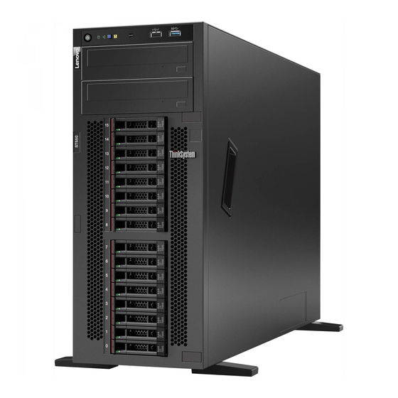
- Page 1 ThinkSystem ST550 Setup Guide Machine Types: 7X09 and 7X10...
- Page 2 Before using this information and the product it supports, be sure to read and understand the safety information and the safety instructions, which are available at: http://thinksystem.lenovofiles.com/help/topic/safety_documentation/pdf_files.html In addition, be sure that you are familiar with the terms and conditions of the Lenovo warranty for your server, which can be found at: http://datacentersupport.lenovo.com/warrantylookup Tenth Edition (May 2020) ©...
-
Page 3: Table Of Contents
Chapter 4. System configuration . . . 111 Hot-swap-drive backplane..Set the network connection for the Lenovo XClarity Parts list.... - Page 4 ThinkSystem ST550 Setup Guide...
-
Page 5: Chapter 1. Introduction
Identifying your server When you contact Lenovo for help, the machine type and serial number information helps support technicians to identify your server and provide faster service. The machine type and serial number are on the ID label on the front of the server. -
Page 6: Server Package Contents
Scan the QR code with a mobile device and a QR code reader application to get quick access to the Lenovo Service web site for this server. The Lenovo Service web site provides additional information for parts installation and replacement videos, and error codes for server support. -
Page 7: Server Form Factor
Material box, including items such as accessory kit, power cords* and documentation Server form factor The ThinkSystem ST550 server is designed to support both tower and rack form factors. You can change the server from tower form factor to rack form factor by installing the tower-to-rack conversion kit. -
Page 8: Features
The Lenovo XClarity Controller consolidates multiple management functions in a single chip on the server system board. Some of the features that are unique to the Lenovo XClarity Controller are enhanced performance, higher- resolution remote video, and expanded security options. For additional information about the Lenovo XClarity Controller, see: http://sysmgt.lenovofiles.com/help/topic/com.lenovo.systems.management.xcc.doc/product_page.html... -
Page 9: Specifications
QR code with a mobile device and a QR code reader application to get quick access to the Lenovo Service web site for this server. The Lenovo Service Information web site provides additional information for parts installation and replacement videos, and error codes for server support. - Page 10 • SUSE Linux Enterprise Server For a complete list of operating systems, see: https://lenovopress.com/osig For OS deployment instructions, see: “Deploy the operating system” on page 116 Supported drives The drives supported by your server vary by model. • Storage drive ThinkSystem ST550 Setup Guide...
- Page 11 Drive bay Supported drive type Hot-swap SAS/SATA/NVMe HDD or SSD (NVMe drives are Eight 2.5-inch drive bays supported only in bays 4–7 if an AnyBay backplane is installed) Hot-swap SAS/SATA/NVMe HDD or SSD (NVMe drives are Sixteen 2.5-inch drive bays supported only in bays 4–7 if an AnyBay backplane is installed) Hot-swap SAS/SATA/NVMe HDD or SSD (NVMe drives are Twenty 2.5-inch drive bays...
- Page 12 35°C (95°F) when one or two graphic adapters are installed. • Fan redundancy function is supported when: – One NVIDIA P600, P620, P2000, P2200, P4000, or RTX4000 graphics adapter is installed – Two NVIDIA P600 or P620 graphics adapters are installed ThinkSystem ST550 Setup Guide...
- Page 13 Differences between the original chassis and new chassis Two types of chassis are available for your server, and different chassis type supports different GPU models. You can identify the chassis type of your server by the rear view of your server or the part number label affixed on the bottom of your server.
- Page 14 Then, remove the power cord. Minimal configuration for debugging • One processor in processor socket 1 • One memory DIMM on slot 3 • One power supply • Two system fans (fan 1 and 2) ThinkSystem ST550 Setup Guide...
- Page 15 Acoustical noise • Sound power levels, idle – 4.0 bels, minimum – 4.7 bels, typical – 5.3 bels, maximum • Sound power levels, operating – 4.1 bels, minimum – 4.7 bels, typical – 5.3 bels, maximum Notes: • These sound power levels are measured in controlled acoustical environments according to procedures specified by ISO 7779 and are reported in accordance with ISO 9296.
-
Page 16: Management Options
• Web interface • REST API Usage and downloads http://sysmgt.lenovofiles.com/help/topic/com.lenovo.systems.management.xcc.doc/ product_page.html Centralized interface for multi-server management. Interface • GUI application • Mobile application Lenovo XClarity Administrator • Web interface • REST API Usage and downloads http://sysmgt.lenovofiles.com/help/topic/com.lenovo.lxca.doc/aug_product_page.html ThinkSystem ST550 Setup Guide... - Page 17 • GUI application Usage and downloads http://sysmgt.lenovofiles.com/help/topic/LXPM/LXPM_introduction.html Series of applications that can integrate management features of Lenovo XClarity Administrator and your server with software used in a certain deployment infrastructure, such as VMware vCenter, Microsoft Admin Center, or Microsoft System Center.
- Page 18 2. Firmware updates are limited to Lenovo XClarity Provisioning Manager, BMC firmware, and UEFI updates only. Firmware updates for optional devices, such as adapters, are not supported. 3. The server UEFI settings for option ROM must be set to UEFI to update firmware using Lenovo XClarity Essentials Bootable Media Creator.
-
Page 19: Chapter 2. Server Components
Drive activity LED (green) Drive status LED (yellow) Foot stands 3.5-inch drive bays 0–3 3.5-inch drive bays 4–7 2.5-inch drive bays 0–7 2.5-inch drive bays 8–15 Optical-drive status LED Optical-drive eject/close button Optical-drive manual-eject hole © Copyright Lenovo 2017, 2020... - Page 20 Note: For the 2.5-inch-drive-bay models that support NVMe drives, you can install up to four NVMe drives in bays 4–7. Optical-drive status LED The optical-drive status LED is blinking in green when the optical drive is working or in the POST process. ThinkSystem ST550 Setup Guide...
- Page 21 Optical-drive eject/close button Press this button to eject or close the optical drive when the server power is on. Optical-drive manual-eject hole Insert a straightened paper clip into the optical-drive manual-eject hole to eject the disc tray when the eject/ close button does not work.
-
Page 22: Front Panel
Note: For the 2.5-inch-drive-bay models that support NVMe drives, you can install up to four NVMe drives in bays 4–7. Front panel The front panel of the server provides controls, connectors, and LEDs. The following illustration shows the control, connectors, and LEDs on the front panel of the server. Figure 6. Front panel ThinkSystem ST550 Setup Guide... - Page 23 Table 3. Components on the front panel Callout Callout Power button with power status LED (green) Simple-swap-drive activity LED (green) Network activity LED (green) System ID button with system ID LED (blue) System error LED (yellow) Opening for temperature sensor XClarity Controller USB connector USB 3.0 connector Power button with power status LED...
- Page 24 Each time you press the system ID button, the state of both the system ID LEDs changes. The LEDs can be changed to on, blinking, or off. You can also use the Lenovo XClarity Controller or a remote management program to change the state of the system ID LEDs to assist in visually locating the server among other servers.
-
Page 25: Rear View
• If the connector is set to have both functions, you can press the system ID button for three seconds to switch between the two functions. For more information, see “Set the network connection for the Lenovo XClarity Controller” on page 111. USB 3.0 connector Used to attach a device that requires a USB 2.0 or 3.0 connection, such as a keyboard, a mouse, or a USB... - Page 26 10 11 12 13 14 15 PCIe slots Your server has six PCIe slots on the system board for you to install appropriate PCIe adapters. For information about the PCIe slots, see “Specifications” on page 5. ThinkSystem ST550 Setup Guide...
- Page 27 The hot-swap redundant power supplies help you avoid significant interruption to the operation of the system when a power supply fails. You can purchase a power supply option from Lenovo and install the power supply to provide power redundancy without turning off the server.
-
Page 28: Rear View Leds
Your server has six PCIe slots on the system board for you to install appropriate PCIe adapters. For information about the PCIe slots, see “Specifications” on page 5. Rear view LEDs The illustration in this section shows the LEDs on the rear the server. Figure 9. Rear view LEDs of the server ThinkSystem ST550 Setup Guide... - Page 29 Each time you press the system ID button, the state of both the system ID LEDs changes. The LEDs can be changed to on, blinking, or off. You can also use the Lenovo XClarity Controller or a remote management program to change the state of the system ID LEDs to assist in visually locating the server among other servers.
-
Page 30: System Board Components
CPU 1 power connector System fan 1 connector Power-interface-board signal connector SAS 4–7 connector SAS 0–3 connector Front-panel-USB connector Internal USB 3.0 connector Operator-information-panel connector Optical-drive-2 signal connector Optical-drive-1 signal connector M.2 module slot CMOS battery connector ThinkSystem ST550 Setup Guide... -
Page 31: Internal Cable Routing
Table 7. Components on the system board (continued) Callout Callout Intrusion switch connector /TPM connector (for only) PCIe slot 6 (for processor 1) PCIe slot 5 (for processor 2) PCIe slot 4 (for processor 2) PCIe slot 3 (for processor 1) PCIe slot 2 (for processor 1) PCIe slot 1 (for processor 1) System fan 4 connector... -
Page 32: Optical Drive
Optical-drive-1 signal connector on the system board Signal cable Signal connector on the optical drive 2 Optical-drive-2 signal connector on the system board Power cable Power connector on each optical drive Backplane 3 power connector on the system board ThinkSystem ST550 Setup Guide... -
Page 33: Tape Drive
Tape drive Use the section to understand the cable routing for the tape drive. SAS tape drive Note: Ensure that all cables are routed through the correct cable clips. Figure 12. Cable routing for the SAS tape drive Cable From An available connector on the RAID adapter Signal cable Signal connector on the tape drive... - Page 34 Figure 13. Cable routing for the USB tape drive Cable From Signal cable Signal connector on the tape drive Internal USB 3.0 connector on the system board Power cable Power connector on the tape drive Backplane 3 power connector on the system board ThinkSystem ST550 Setup Guide...
-
Page 35: Power Interface Board
Power interface board Use the section to understand the cable routing for the power interface board. Note: Ensure that all cables are routed through the correct cable clips. Figure 14. Cable routing for the power interface board Cable From Signal cable Signal connector on the power interface Power-interface-board signal connector on board... -
Page 36: Graphics Adapter
Figure 15. Cable routing for the graphics adapters Cable From Power cable Power connector on one graphics adapter GPU 1 connector on the power interface board Power cable Power connector on another graphics GPU 2 connector on the power interface adapter board ThinkSystem ST550 Setup Guide... -
Page 37: Server Models With Eight 3.5-Inch Simple-Swap Drives
Server models with eight 3.5-inch simple-swap drives Use this section to understand the cable routing for server models with eight 3.5-inch simple-swap drives. Note: Ensure that all cables are routed through the correct cable clips. Figure 16. Cable routing for server models with eight 3.5-inch simple-swap drives From Signal cable on backplate 1 SAS 0–3 connector on the system board... -
Page 38: Hot-Swap-Drive Backplane
Before you route cables for backplanes, observe the following guidelines when select a PCIe slot: • The NVMe adapter can be installed only in PCIe slot 2. • Internal RAID adapters can be installed in either PCIe slot 1 or PCIe slot 2. ThinkSystem ST550 Setup Guide... - Page 39 Server models with sixteen 2.5-inch hot-swap drives Use this section to understand the cable routing for server models with sixteen 2.5-inch hot-swap drives. Server model: sixteen 2.5-inch SAS/SATA drives, two 8i RAID adapters Notes: • Ensure that all cables are routed through the correct cable clips. •...
- Page 40 Power cable for backplane 2 Power connector on backplane 2 Backplane 2 power connector on the system board Power cable for backplane 1 Power connector on backplane 1 Backplane 1 power connector on the system board ThinkSystem ST550 Setup Guide...
- Page 41 Server model: twelve 2.5-inch SAS/SATA drives, four 2.5-inch SAS/SATA/NVMe drives, one 16i RAID adapter, one NVMe adapter Notes: • Ensure that all cables are routed through the correct cable clips. • Broken lines indicate the hidden parts. Figure 19. Cable routing for server models with twelve 2.5-inch SAS/SATA drives, four 2.5-inch SAS/SATA/NVMe drives, one 16i RAID adapter, and one NVMe adapter Cable From...
- Page 42 • Ensure that all cables are routed through the correct cable clips. • Broken lines indicate the hidden parts. Figure 20. Cable routing for server models with twelve 2.5-inch SAS/SATA drives, four 2.5-inch SAS/SATA/NVMe drives, one 16i RAID adapter, and one NVMe adapter ThinkSystem ST550 Setup Guide...
- Page 43 Cable From SAS signal cable for SAS 0 and SAS 1 connectors on C0 and C1 connectors on the 8i RAID backplane 1 backplane 1 adapter NVMe signal cable for NVMe 0, NVMe 1, and NVMe 2, and C0, C1, C2, and C3 connectors on the backplane 1 NVMe 3 connectors on backplane 1 NVMe adapter...
- Page 44 Power connector on backplane 1 Backplane 1 power connector on the system board SAS signal cable for SAS 0 and SAS 1 connectors on C2 and C3 connectors on the 24i RAID backplane 2 backplane 2 adapter ThinkSystem ST550 Setup Guide...
- Page 45 Cable From SAS signal cable for SAS connector on backplane 3 C4 connector on the 24i RAID adapter backplane 3 Power cable for backplane 2 Power connector on backplane 2 Backplane 2 power connector on the system board Power cable for backplane 3 Power connector on backplane 3 Backplane 3 power connector on the system board...
- Page 46 Power cable for backplane 1 Power connector on backplane 1 Backplane 1 power connector on the system board Power cable for backplane 2 Power connector on backplane 2 Backplane 2 power connector on the system board ThinkSystem ST550 Setup Guide...
- Page 47 Cable From SAS signal cable for SAS connector on backplane 3 C0 connector on the 8i RAID adapter backplane 3 Power cable for backplane 3 Power connector on backplane 3 Backplane 3 power connector on the system board Chapter 2 Server components...
- Page 48 SAS 0 and SAS 1 connectors on C0 and C1 connectors on the 24i RAID backplane 1 backplane 1 adapter Power cable for backplane 1 Power connector on backplane 1 Backplane 1 power connector on the system board ThinkSystem ST550 Setup Guide...
- Page 49 Cable From SAS signal cable for SAS 0 and SAS 1 connectors on C2 and C3 connectors on the 24i RAID backplane 2 backplane 2 adapter SAS signal cable for SAS connector on backplane 3 C4 connector on the 24i RAID adapter backplane 3 Power cable for backplane 3 Power connector on backplane 3...
- Page 50 Power cable for backplane 1 Power connector on backplane 1 Backplane 1 power connector on the system board Power cable for backplane 2 Power connector on backplane 2 Backplane 2 power connector on the system board ThinkSystem ST550 Setup Guide...
- Page 51 Server models with eight 3.5-inch hot-swap drives and four 2.5-inch hot-swap drives Use this section to understand the cable routing for server models with eight 3.5-inch hot-swap SAS/SATA drives and four 2.5-inch hot-swap SAS/SATA drives. Server model: eight 3.5-inch hot-swap SAS/SATA drives, four 2.5-inch hot-swap SAS/SATA drives, two 8i RAID adapters Notes: •...
- Page 52 SAS signal cable for SAS connector on backplane 3 C0 connector on another 8i RAID backplane 3 adapter Power cable for backplane 3 Power connector on backplane 3 Backplane 3 power connector on the system board ThinkSystem ST550 Setup Guide...
- Page 53 Server model: eight 3.5-inch hot-swap SAS/SATA drives, four 2.5-inch hot-swap SAS/SATA drives, one 16i RAID adapter Notes: • Ensure that all cables are routed through the correct cable clips. • Broken lines indicate the hidden parts. Figure 26. Cable routing for server models with eight 3.5-inch hot-swap SAS/SATA drives, four 2.5-inch hot-swap SAS/ SATA drives, and one 24i RAID adapter Chapter 2 Server components...
- Page 54 SAS signal cable for SAS connector on backplane 3 C2 connector on the 24i RAID adapter backplane 3 Power cable for backplane 3 Power connector on backplane 3 Backplane 3 power connector on the system board ThinkSystem ST550 Setup Guide...
-
Page 55: Parts List
Use the parts list to identify each of the components that are available for your server. For more information about ordering the parts shown in Figure 27 “Server components” on page 52: http://datacentersupport.lenovo.com/us/en/products/servers/thinksystem/st550/7x09/parts Note: Depending on the model, your server might look slightly different from the illustration. - Page 56 Tier 1 CRU at your request with no service agreement, you will be charged for the installation. • Tier 2 customer replaceable unit: You may install a Tier 2 CRU yourself or request Lenovo to install it, at no additional charge, under the type of warranty service that is designated for your server.
- Page 57 • Consumable and Structural parts: Purchase and replacement of consumable and structural parts is your responsibility. If Lenovo acquires or installs a structural component at your request, you will be charged for the service. Table 8. Parts listing Consumable Description...
- Page 58 M.2 retainer clip √ Heat sink √ System board √ √ DIMM √ PCIe adapter √ Serial port module √ Front fan √ Rear fan √ Hot-swap power supply √ Hot-swap power supply cage √ Fixed power supply ThinkSystem ST550 Setup Guide...
-
Page 59: Power Cords
Several power cords are available, depending on the country and region where the server is installed. To view the power cords that are available for the server: 1. Go to: http://dcsc.lenovo.com/#/ 2. Click Preconfigured Model or Configure to order. 3. Enter the machine type and model for your server to display the configurator page. - Page 60 ThinkSystem ST550 Setup Guide...
-
Page 61: Chapter 3. Server Hardware Setup
Validate that the server hardware was set up successfully. See “Validate server setup” on page 109. 3. Configure the system. a. Connect the Lenovo XClarity Controller to the management network. See “Set the network connection for the Lenovo XClarity Controller” on page 111. -
Page 62: Installation Guidelines
Go to to download firmware updates for your server. ThinkSystem ST550 Drivers and Software Important: Some cluster solutions require specific code levels or coordinated code updates. If the component is part of a cluster solution, verify that the latest level of code is supported for the cluster solution before you update the code. -
Page 63: System Reliability Guidelines
• The Red strip on the drives, adjacent to the release latch, indicates that the drive can be hot-swapped if the server and operating system support hot-swap capability. This means that you can remove or install the drive while the server is still running. Note: See the system specific instructions for removing or installing a hot-swap drive for any additional procedures that you might need to perform before you remove or install the drive. -
Page 64: Install Server Hardware Options
To remove the server cover, complete the following steps: Watch the procedure. A video of the removal process is available: • Youtube: https://www.youtube.com/playlist?list=PLYV5R7hVcs-Acsjj4tU79GzKnWG316BYn • Youku: http://list.youku.com/albumlist/show/id_50483452 ThinkSystem ST550 Setup Guide... -
Page 65: Remove The Air Baffle
Figure 28. Server cover removal Step 1. Use the key attached on the rear of the server to turn the cover lock to the open position. Step 2. Slide the server cover toward the rear of the server until the server cover is disengaged from the chassis. -
Page 66: Remove The Pcie Adapter Retainer
“Power off installation the server Guidelines” on for this task” page 58 on page 109 To remove the PCIe adapter retainer, complete the following step: Watch the procedure. A video of the removal process is available: ThinkSystem ST550 Setup Guide... -
Page 67: Remove The Pcie Adapter Holder
• Youtube: https://www.youtube.com/playlist?list=PLYV5R7hVcs-Acsjj4tU79GzKnWG316BYn • Youku: http://list.youku.com/albumlist/show/id_50483452 Figure 30. PCIe adapter retainer removal Step 1. Grab the touch point to lift the retainer from the chassis. Remove the PCIe adapter holder Use this information to remove the PCIe adapter holder. “Read the “Power off installation the server... - Page 68 Step 2. Remove the PCIe adapter holder in the direction as shown. ThinkSystem ST550 Setup Guide...
-
Page 69: Install A Processor-Heat-Sink Module
• PHMs are keyed for the socket where they can be installed and for their orientation in the socket. • See http://www.lenovo.com/us/en/serverproven/ for a list of processors supported for your server. All processors on the system board must have the same speed, number of cores, and frequency. - Page 70 With the processor-contact side up, flex the ends of the retainer down and away from the processor to release the retaining clips; then, remove the processor from the retainer. Discard the old retainer. ThinkSystem ST550 Setup Guide...
- Page 71 2. Install the square retainer. Figure 33. Installing a processor retainer a. Position the processor on the new retainer so that the triangular marks align; then, insert the unmarked end of the processor into the retainer. b. Holding the inserted end of the processor in place, flex the opposite end of the retainer down and away from the processor until you can press the processor under the clip on the retainer.
- Page 72 1. If you are installing the second PHM, remove the fan filler and install the new system fan that comes with the processor option kit. See “Install a front fan” on page 95. 2. If there are DIMMs to install, install them. See “Install a DIMM” on page 69. ThinkSystem ST550 Setup Guide...
-
Page 73: Install A Dimm
Install a DIMM Use this information to install a DIMM. “Read the “Power off “ATTENTION: installation the server for Static Sensitive Device Guidelines” on this task” on Ground package before opening” page 58 page 109 on page 59 Attention: DIMMs are sensitive to static discharge and require special handling. In addition to the standard guidelines for Handling static-sensitive devices: •... - Page 74 • Minimum: 8 GB (one processor and one 8GB registered DIMM (RDIMM)installed) • Maximum: – 384 GB using RDIMMs (two processors and twelve 32 GB registered DIMMs (RDIMMs)installed) – 768 GB using LRDIMMs (two processors and twelve 64 GB load-reduced DIMMs (LRDIMMs) installed) • Type: ThinkSystem ST550 Setup Guide...
- Page 75 – TruDDR4 2933, single-rank/dual-rank, 8 GB/16 GB/32 GB/64 GB registered DIMMs (RDIMMs) For a list of supported DIMM options, see: http://www.lenovo.com/us/en/serverproven/ Before installing a DIMM, ensure that all DIMMs to be installed must be the same type. Your server supports the following types of DIMMs: •...
- Page 76 (CPU1 and CPU2) are installed. Notes: • If there are three identical DIMMs to be installed for CPU1, and the three DIMMs have the same Lenovo part number, install the three DIMMs in slots 1, 2, and 3. • If there are three identical DIMMs to be installed for CPU2, and the three DIMMs have the same Lenovo part numbers, install the three DIMMs in slots 10, 11, and 12.
- Page 77 Mirroring mode In mirroring mode, each DIMM in a pair must be identical in size and architecture. The channels are grouped in pairs with each channel receiving the same data. One channel is used as a backup of the other, which provides redundancy.
-
Page 78: Install An Optical Drive Or A Tape Drive
Use this information to install an optical drive or a tape drive. “Read the “Power off “ATTENTION: installation the server for Static Sensitive Device Guidelines” on this task” on Ground package before opening” page 58 page 109 on page 59 ThinkSystem ST550 Setup Guide... - Page 79 S006 CAUTION: When laser products (such as CD-ROMs, DVD drives, fiber optic devices, or transmitters) are installed, note the following: • Do not remove the covers. Removing the covers of the laser product could result in exposure to hazardous laser radiation. There are no serviceable parts inside the device. •...
- Page 80 Then, take the new optical drive or tape drive out of the package and place it on a static-protective surface. To install an optical drive or a tape drive, complete the following steps: ThinkSystem ST550 Setup Guide...
- Page 81 Step 1. Remove the retainer from the chassis. Figure 39. Drive retainer removal Step 2. Install the retainer on only the left side of the optical drive or tape drive. Figure 40. Optical drive retainer installation Step 3. Hold the optical drive or tape drive in correct orientation and then slide it into the drive bay until it snaps into position.
-
Page 82: Install The Expansion Drive Cage
1. Fan 3 is required after the expansion drive cage is installed. If your server does not come with Fan 3, purchase the front fan option before you install the expansion drive cage. Note: The front fan option name is ThinkSystem ST550 Front Mid Fan Module for 4x2.5" ODD Conversion. -
Page 83: Install A Simple-Swap-Drive Backplate
After installing the expansion drive cage, ensure that: • The signal cables are secured by the clips • The signal cables are bound correctly by the Velcro strap shipped in the package. Figure 43. Securing and binding the signal cables correctly Install a simple-swap-drive backplate Use this information to install a simple-swap-drive backplate. -
Page 84: Install A Backplane
To install the backplane for eight 2.5-inch hot-swap drives, complete the following steps: Watch the procedure. A video of the installation process is available: • Youtube: https://www.youtube.com/playlist?list=PLYV5R7hVcs-Acsjj4tU79GzKnWG316BYn • Youku: http://list.youku.com/albumlist/show/id_50483452 Step 1. Note the orientation of the new backplane. ThinkSystem ST550 Setup Guide... - Page 85 Step 2. Lower the new backplane into the chassis and insert the new backplane into the backplane slot. Then, carefully rotate the top edge of the new backplane toward the drive cage until it is secured by the release tab. Figure 45.
-
Page 86: Install A Pcie Adapter
• Depending on the specific type, your PCIe adapter might look different from the illustration in this topic. • Use any documentation that comes with the PCIe adapter and follow those instructions in addition to the instructions in this topic. ThinkSystem ST550 Setup Guide... -
Page 87: Install The Serial Port Module
Before installing a PCIe adapter: 1. If a bracket is installed in the PCIe slot, remove it. Store the bracket for the PCIe slot in case that you later remove the PCIe adapter and need the bracket to cover the place. 2. -
Page 88: Install The M.2 Backplane And M.2 Drive
Services (EMS) feature: Bcdedit /ems no 3. Restart the server to ensure that the EMS setting takes effect. Install the M.2 backplane and M.2 drive Use this information to install the M.2 backplane and M.2 drive. ThinkSystem ST550 Setup Guide... - Page 89 “Read the “Power off “ATTENTION: installation the server for Static Sensitive Device Guidelines” on this task” on Ground package before opening” page 58 page 109 on page 59 Before installing the M.2 backplane and M.2 drive: 1. Touch the static-protective package that contains the new M.2 backplane and M.2 drive to any unpainted surface on the outside of the server.
- Page 90 Attention: When sliding the retainer forward, ensure that the two nubs on the retainer enter the small holes on the M.2 backplane. Once they enter the holes, you will hear a soft “click” sound. Figure 51. Instruction for sliding the retainer ThinkSystem ST550 Setup Guide...
- Page 91 Then, insert the M.2 backplane into the M.2 slot on the system board and press it down to fully seat it. Figure 52. M.2 backplane installation After installing the M.2 drive and M.2 backplane, use the Lenovo XClarity Provisioning Manager to configure the RAID. For more information, see: http://sysmgt.lenovofiles.com/help/topic/LXPM/RAID_setup.html Adjust the retainer on the M.2 backplane...
-
Page 92: Install The Hot-Swap Power Supply Cage
Then, take the new cage out of the package and place them on a static-protective surface. To install the hot-swap power supply cage, complete the following steps: ThinkSystem ST550 Setup Guide... -
Page 93: Install The Power Interface Board
Figure 54. Hot-swap power supply cage installation Step 1. Slide the new hot-swap power supply cage into the bay as shown until it snaps into position. Step 2. Install the screws to secure the hot-swap power supply cage. Install the power interface board Use this information to install the power interface board. -
Page 94: Install A Hot-Swap Power Supply
• Ensure that the devices that you are installing are supported. For a list of supported optional devices for the server, go to: http://www.lenovo.com/us/en/serverproven/ Notes: – Ensure that the two power supplies installed on the server have the same wattage. ThinkSystem ST550 Setup Guide... - Page 95 – If you are replacing the existing power supply with a new power supply of different wattage, attach the power information label that comes with this option onto the existing label near the power supply. Figure 56. Hot-swap power supply label S035 CAUTION: Never remove the cover on a power supply or any part that has this label attached.
- Page 96 240 V dc input cannot support hot plugging power cord function. Before removing the power supply with dc input, please turn off server or disconnect dc power sources at the breaker panel or by turning off the power source. Then, remove the power cord. ThinkSystem ST550 Setup Guide...
- Page 97 在直流输入状态下,若电源供应器插座不支持热插拔功能,请务必不要对设备电源线进行热插拔,此操作可能 导致设备损坏及数据丢失。因错误执行热插拔导致的设备故障或损坏,不属于保修范围。 NEVER CONNECT AND DISCONNECT THE POWER SUPPLY CABLE AND EQUIPMENT WHILE YOUR EQUIPMENT IS POWERED ON WITH DC SUPPLY (hot-plugging). Otherwise you may damage the equipment and result in data loss, the damages and losses result from incorrect operation of the equipment will not be covered by the manufacturers’...
- Page 98 To install a hot-swap power supply, complete the following steps: Watch the procedure. A video of the installation process is available: • Youtube: https://www.youtube.com/playlist?list=PLYV5R7hVcs-Acsjj4tU79GzKnWG316BYn • Youku: http://list.youku.com/albumlist/show/id_50483452 ThinkSystem ST550 Setup Guide...
-
Page 99: Install A Front Fan
Step 1. If there is a power-supply-bay filler installed, remove it. Important: To ensure proper cooling during normal server operation, both of the power supply bays must be occupied. This means that each bay must have a power supply installed; or one has a power supply installed and the other has a power-supply filler installed. - Page 100 Touch the static-protective package that contains the new front fan to any unpainted surface on the outside of the server. Then, take the new front fan out of the package and place it on a static- protective surface. ThinkSystem ST550 Setup Guide...
-
Page 101: Install The Rear Fan
Step 2. Align the pins on the front fan with the corresponding holes in the chassis. Then, pivot the front fan forward until it snaps into place. Figure 59. Front fan installation Step 3. Connect the front fan cable to the corresponding fan connector on the system board. For the location of the system fan connectors, see “System board components”... -
Page 102: Install The Pcie Adapter Holder
4 connector, see “System board components” on page 26. Install the PCIe adapter holder Use this information to install the PCIe adapter holder. “Read the “Power off installation the server Guidelines” on for this task” page 58 on page 109 ThinkSystem ST550 Setup Guide... -
Page 103: Install The Pcie Adapter Retainer
To install the PCIe adapter holder, complete the following steps: Figure 61. PCIe adapter holder installation Step 1. Insert the PCIe-adapter-holder post into the corresponding recess in the chassis. Step 2. Secure the three notches on the PCIe adapter holder with the three mounting studs on the chassis. Step 3. -
Page 104: Install The Air Baffle
S017 CAUTION: Hazardous moving fan blades nearby. Before installing the air baffle, ensure that all cables inside the server have been properly routed so that they will not interfere with the air baffle. ThinkSystem ST550 Setup Guide... -
Page 105: Install The Raid Super Capacitor Module
To install the air baffle, complete the following steps: Watch the procedure. A video of the installation process is available: • Youtube: https://www.youtube.com/playlist?list=PLYV5R7hVcs-Acsjj4tU79GzKnWG316BYn • Youku: http://list.youku.com/albumlist/show/id_50483452 Figure 63. Air baffle installation Step 1. Carefully insert the rear end of the air baffle into the chassis. Step 2. -
Page 106: Install The Server Cover
Ground package before opening” page 58 page 109 on page 59 S033 CAUTION: Hazardous energy present. Voltages with hazardous energy might cause heating when shorted with metal, which might result in spattered metal, burns, or both. ThinkSystem ST550 Setup Guide... - Page 107 S014 CAUTION: Hazardous voltage, current, and energy levels might be present. Only a qualified service technician is authorized to remove the covers where the label is attached. Before installing the server cover: 1. Ensure that all adapters and other components are installed and seated correctly and that you have not left loose tools or parts inside the server.
-
Page 108: Install The Foot Stands
• For a complete list of supported optional devices for the server, see: http://www.lenovo.com/us/en/serverproven/ • The drive bays are numbered to indicate the installation order (starting from number “0”). Follow the installation order when you install a drive. See “Front view” on page 15. ThinkSystem ST550 Setup Guide... - Page 109 • You can mix drives of different types, different sizes, and different capacities in one system, but not in one RAID array. The following order is recommended when installing the drives: – Drive type priority: SSD, SATA HDD – Drive capacity priority: the lowest capacity first •...
-
Page 110: Install A Hot-Swap Drive
For a complete list of supported optional devices for the server, see: http://www.lenovo.com/us/en/serverproven/ • The drive bays are numbered to indicate the installation order (starting from number “0”). Follow the installation order when you install a drive. See “Front view” on page 15. ThinkSystem ST550 Setup Guide... - Page 111 • You can mix drives of different types, different sizes, and different capacities in one system, but not in one RAID array. The following order is recommended when installing the drives: – Drive type priority: NVMe SSD, SAS SSD, SATA SSD, SAS HDD, SATA HDD –...
-
Page 112: Cable The Server
• The server can restart automatically after a power interruption. • The server can respond to remote power-on requests sent to the Lenovo XClarity Controller. For information about powering off the server, see “Power off the server” on page 109. -
Page 113: Validate Server Setup
Power off the server The server remains in a standby state when it is connected to a power source, allowing the Lenovo XClarity Controller to respond to remote power-on requests. To remove all power from the server (power-on LED off), you must disconnect all power cables. - Page 114 ThinkSystem ST550 Setup Guide...
-
Page 115: Chapter 4. System Configuration
The following methods are available to set the network connection for the Lenovo XClarity Controller if you are not using DHCP: • If a monitor is attached to the server, you can use Lenovo XClarity Controller to set the network connection. -
Page 116: Update The Firmware
Machine-type-specific firmware-only UXSPs are also available. See the following table to determine the best Lenovo tool to use for installing and setting up the firmware: Note: The server UEFI settings for option ROM must be set to Auto or UEFI to update firmware using Lenovo XClarity Administrator or Lenovo XClarity Essentials. - Page 117 The latest firmware can be found at the following site: http://datacentersupport.lenovo.com/us/en/products/servers/thinksystem/st550/7X09/downloads • Lenovo XClarity Provisioning Manager From Lenovo XClarity Provisioning Manager, you can update the Lenovo XClarity Controller firmware, the UEFI firmware, and the Lenovo XClarity Provisioning Manager software. Chapter 4...
- Page 118 Additional information about using Lenovo XClarity Provisioning Manager to update firmware is available http://sysmgt.lenovofiles.com/help/topic/LXPM/platform_update.html • Lenovo XClarity Controller If you need to install a specific update, you can use the Lenovo XClarity Controller interface for a specific server. Notes: – To perform an in-band update through Windows or Linux, the operating system driver must be installed and the Ethernet-over-USB (sometimes called LAN over USB) interface must be enabled.
-
Page 119: Configure The Firmware
If you are managing multiple servers using the Lenovo XClarity Administrator, you can update firmware for all managed servers through that interface. Firmware management is simplified by assigning firmware- compliance policies to managed endpoints. When you create and assign a compliance policy to managed endpoints, Lenovo XClarity Administrator monitors changes to the inventory for those endpoints and flags any endpoints that are out of compliance. -
Page 120: Raid Configuration
OS logical drives or volumes. An introduction to RAID is available at the following Lenovo Press website: https://lenovopress.com/lp0578-lenovo-raid-introduction Detailed information about RAID management tools and resources is available at the following Lenovo Press website: https://lenovopress.com/lp0579-lenovo-raid-management-tools-and-resources Deploy the operating system Several options are available to deploy an operating system on the server. -
Page 121: Back Up The Server Configuration
Alternatively, you can use the s s a a v v e e command from Lenovo XClarity Essentials OneCLI to create a backup of all configuration settings. For more information about the s s a a v v e e command, see: http://sysmgt.lenovofiles.com/help/topic/toolsctr_cli_lenovo/onecli_r_save_command.html... - Page 122 ThinkSystem ST550 Setup Guide...
-
Page 123: Chapter 5. Resolving Installation Issues
• “Displayed system memory less than installed physical memory” on page 121 • “A Lenovo optional device that was just installed does not work.” on page 121 • “Voltage planar fault is displayed in the event log” on page 121... - Page 124 • Replace the affected backplane signal cable. • Replace the affected backplane. 8. Run the diagnostics tests for the hard disk drives. When you start a server and press F1, the Lenovo XClarity Provisioning Manager interface is displayed by default. You can perform hard drive diagnostics from this interface.
- Page 125 • There is no memory mismatch when the server is at the minimum memory configuration. 2. Reseat the DIMMs, and then restart the server. 3. Run memory diagnostics. When you start a server and press F1, the Lenovo XClarity Provisioning Manager interface is displayed by default. You can perform memory diagnostics from this interface.
- Page 126 • If the system restarts, add each of the items that you removed one at a time, restarting the system each time, until the error occurs. Replace the item for which the error occurs. • If the system does not restart, suspect the system board. ThinkSystem ST550 Setup Guide...
-
Page 127: Appendix A. Getting Help And Technical Assistance
Appendix A. Getting help and technical assistance If you need help, service, or technical assistance or just want more information about Lenovo products, you will find a wide variety of sources available from Lenovo to assist you. On the World Wide Web, up-to-date information about Lenovo systems, optional devices, services, and support are available at: http://datacentersupport.lenovo.com... -
Page 128: Collecting Service Data
Collecting service data To clearly identify the root cause of a server issue or at the request of Lenovo Support, you might need collect service data that can be used for further analysis. Service data includes information such as event logs and hardware inventory. -
Page 129: Contacting Support
• Lenovo XClarity Essentials OneCLI Lenovo XClarity Essentials OneCLI has inventory application to collect service data. It can run both in- band and out-of-band. When running in-band within the host operating system on the server, OneCLI can collect information about the operating system, such as the operating system event log, in addition to the hardware service data. - Page 130 ThinkSystem ST550 Setup Guide...
-
Page 131: Appendix B. Trademarks
Intel and Xeon are trademarks of Intel Corporation in the United States, other countries, or both. Microsoft and Windows are trademarks of the Microsoft group of companies. Linux is a registered trademark of Linus Torvalds. All other trademarks are the property of their respective owners. © 2020 Lenovo © Copyright Lenovo 2017, 2020... - Page 132 ThinkSystem ST550 Setup Guide...
-
Page 133: Index
2.5-inch hot-swap drives guidelines cable the server installation guidelines collecting service data installing Common installation issues air baffle Configuration - ThinkSystem ST550 backplane 80–81 configure the firmware DIMM expansion drive cage option install foot stands creating a personalized support web page... - Page 134 PCIe adapter retainer system board components installing System configuration - ThinkSystem ST550 removing system error LED system ID button option install system ID LED power button system reliability guidelines power cords...