Table of Contents
Advertisement
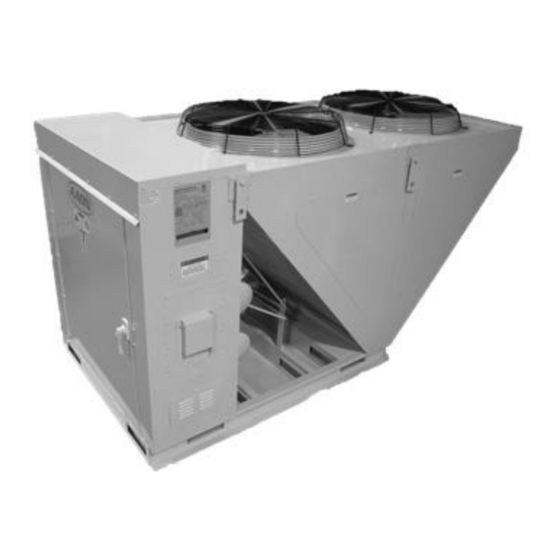
Condenser and Condensing Units
Installation, Operation,
WARNING
If the information in this manual is not
followed exactly, a fire or explosion
may result causing property damage,
personal injury or loss of life.
WARNING
FOR YOUR SAFETY
Do not store or use gasoline or other
flammable vapors and liquids in the
vicinity of this or any other appliance.
& Maintenance
CF Series
WARNING
QUALIFIED INSTALLER
Improper
installation,
alteration, service or maintenance
can
cause
property
personal
injury
Installation and service must be
performed by a Factory Trained
Service Technician. A copy of this
IOM should be kept with the unit.
adjustment,
damage,
or
loss
of
life.
Advertisement
Table of Contents

Related Manuals for AAON CF Series


Summary of Contents for AAON CF Series
- Page 1 CF Series Condenser and Condensing Units Installation, Operation, & Maintenance WARNING WARNING QUALIFIED INSTALLER If the information in this manual is not followed exactly, a fire or explosion Improper installation, adjustment, may result causing property damage, alteration, service or maintenance personal injury or loss of life.
-
Page 2: Table Of Contents
Table of Contents AAON CF Series Features and Options Introduction..............5 Safety .............................. 6 CF Series Feature String Nomenclature ..................11 General Information ........................14 Codes and Ordinances ....................... 14 Receiving Unit ........................... 14 Storage ............................15 Wiring Diagrams ........................16 General Maintenance ......................... - Page 3 Figure 2 - Forklifting a CF Series B and C Cabinet ..............17 Figure 3 – Lifting Details and Orientation of a CF Series 9-70 ton Condensing Unit ....18 Figure 4 - Orientation of Series 2-7 ton Condensing Unit ............18 Figure 5 - Adjustable Fan Cycling Switch ..................
- Page 4 Figure 27 - A/C with Modulating Hot Gas Reheat and Hot Gas Bypass Split System Piping, Suction Down..........................56 Figure 28 - A/C with Modulating Hot Gas Reheat and Hot Gas Bypass Split System Piping, Suction Up ............................ 57 Figure 29 - A/C with Modulating Hot Gas Reheat and Hot Gas Bypass + LAC Split System Piping, Suction Down ........................
-
Page 5: Aaon Cf Series Features And Options Introduction
AAON CF Series Features and Options Introduction Energy Efficiency System Integration • • Staged, Two-Step, 10-100% Variable Complete Split System with AAON DX Capacity, or Tandem R-410A Scroll Air Handling Units • Compressors Single Point Non-Fused Disconnect • Air-Source Heat Pump Power Switch •... -
Page 6: Safety
Safety Attention should be paid to the following statements: NOTE - Notes are intended to clarify the unit installation, operation and maintenance. CAUTION - Caution statements are given to prevent actions that may result in equipment damage, property damage, or personal injury. WARNING - Warning statements are given to prevent actions that could result in equipment damage, property damage, personal injury or death. - Page 7 WARNING WARNING FIRE, EXPLOSION OR CARBON GROUNDING REQUIRED MONOXIDE POISONING HAZARD All field installed wiring must be Failure to replace proper controls completed by qualified personnel. Field installed wiring must comply could result in fire, explosion or with NEC/CEC, local state carbon monoxide poisoning.
- Page 8 CAUTION CAUTION VARIABLE FREQUENCY DRIVES DOOR LATCHES Door compartments containing Electric motor over-current protection hazardous voltage or rotating parts and overload protection may be a are equipped with door latches that function of the Variable Frequency allow locks. Door latches are shipped Drive to which the motors are wired.
- Page 9 CAUTION CAUTION COMPRESSOR LUBRICANT COIL CLEANING Polyolester (POE) and Polyvinylether Do not clean DX refrigerant coils with (PVE) oils are two types of lubricants hot water or steam. The use of hot used in hydrofluorocarbon (HFC) water or steam on refrigerant coils refrigeration systems.
- Page 10 WARNING COMPRESSOR CYCLING 5 MINUTE MINIMUM OFF TIME prevent motor overheating compressors must cycle off for a minimum of 5 minutes. 5 MINUTE MINIMUM ON TIME To maintain the proper oil level compressors must cycle on for a minimum of 5 minutes. The cycle rate must not exceed 6 starts per hour.
-
Page 11: Cf Series Feature String Nomenclature
CF Series Feature String Nomenclature Model Options Unit Feature Options CF A - 015 - B - A - 3 - D C 0 0 K : 0 - A 0 - E 0 - C 0 - A N 0 - B - D E 0 0 - 0 0 A 0 E 0 0... - Page 12 CF Series Feature String Nomenclature Model Options Unit Feature Options CF A - 015 - B - A - 3 - D C 0 0 K : 0 - A 0 - E 0 - C 0 - A N 0 - B...
- Page 13 H = Options A + E B = Premium AAON Gray Paint Exterior J = Options B + C E = Premium AAON Gray Paint Ext + Shrink Wrap L = Options B + E X = SPA + Premium AAON Gray Paint Exterior...
-
Page 14: General Information
Codes and Ordinances transit. If damage is found it should be noted CF Series units have been tested and on the carrier’s freight bill. A request for certified, by ETL, in accordance with UL inspection by carrier’s agent should be made... -
Page 15: Storage
The warranty card must be completed in full prevent refrigerant migration. This means and returned to AAON not more than 3 the compressor will cool down, and liquid months after the unit is delivered. refrigerant accumulate compressor. -
Page 16: Wiring Diagrams
The variable capacity compressors must be CAUTION on a minimum of 3 minutes and off for a minimum of 3 minutes. The cycle rate must COMPRESSOR ROTATION be no more than 6 starts per hour. Scroll compressors are directional The compressor life will be seriously and will be damaged by operation in shortened by reduced lubrication, and the the wrong direction. -
Page 17: Installation
Forks or Fork Extensions must be at the forks are no more than 6” away from the least 72” in length. edge of the unit. Figure 2 - Forklifting a CF Series B and C Figure 1 - Forklifting a CF Series A Cabinet Cabinet... -
Page 18: Lifting The Unit
If cables or chains are used to hoist the unit damage due to vandalism or other causes. they must be the same length. Minimum cable length is 99” for CF Series 9-70 ton The first clearance table below gives the units. CF Series 2-7 ton units do not include clearance values for proper unit operation. -
Page 19: Mounting Isolation
Do not prevent liquid refrigerant from slugging the place the unit under an overhang. CF Series compressors during startup in low ambient condensers and condensing units that have a conditions. -
Page 20: Fan Cycling Low Ambient
At the same time the bypassed hot gas raises liquid pressure in the receiver, allowing the system to operate properly. CF Series condensers and condensing units use an Figure 5 - Adjustable Fan Cycling Switch LAC valve for low ambient operation. -
Page 21: Condenser Flooding
Figure 6 - Piping Schematic of Example System using the LAC Valve Condenser Flooding Table 3 - Condenser Flooding In order to maintain head pressure in the PERCENTAGE OF CONDENSER TO BE FLOODED refrigeration system, liquid refrigerant is kept in the condenser coil to reduce Ambient °... -
Page 22: Refrigerant Piping
Excessive suction line pressure drop causes All CF Series condensing units are provided loss of compressor capacity and increased with in-line shutoff valves on both the liquid power usage resulting in reduced system and suction lines. -
Page 23: Liquid Line
Use temperature and Special piping provisions must be taken pressure measurements to determine when lines are up vertical risers or in liquid sub-cooling, not the sight glass. excessively long line runs. AAON does not recommend running underground Liquid Line Routing refrigerant lines. -
Page 24: Suction Line
Liquid Line Guidelines return oil to the compressor at minimum In order to ensure liquid at the TXV, the loading conditions. However, reducing the sum of frictional losses and pressure loss piping diameter to increase the velocity at due to vertical rise must not exceed minimal load can result in excessive available sub-cooling. -
Page 25: Figure 7 - Double Suction Riser Construction
to carry oil up both risers, and it collects in Suction Line Traps the trap, effectively closing off the larger Include a trap immediately after the diameter riser, and diverting refrigerant up evaporator coil outlet to protect the TXV the small riser where velocity of the bulb from liquid refrigerant. -
Page 26: Discharge Line
The same line must be used for both modes the suction line. Pressure loss in the of operation. discharge line causes the compressors to work harder and thus use more power. In a fashion similar to the liquid line, a common guideline to consider is a system Discharge Line Routing design with pressure losses due to friction... -
Page 27: Figure 8 - Heat Pump Piping Schematic Of Suction Vapor Flow Down In Double Riser
At full load, the mass flow clears the trap of cooling mode. The discharge velocity in the oil, and refrigerant is carried through both riser during heating mode is much lower risers. The smaller diameter pipe should be than the suction velocity during cooling sized to return oil at minimum load, while mode. -
Page 28: Hot Gas Bypass Line
corresponding 1-2°F change in saturation Discharge Line Traps temperature. Include traps every 12 feet in vertical discharge riser sections. For split system piping with long horizontal runs and short vertical risers, a smaller pipe Discharge Line Insulation size can be used to provide sufficient Although a typical discharge line does not velocity to return oil in vertical risers at part need to be insulated, the suction line does. -
Page 29: Hot Gas Reheat
Hot Gas Reheat When installing vertical hot gas bypass The AAON modulating hot gas reheat lines, an oil drip line must be provided at the system diverts hot discharge gas from the lowest point in the system. The oil drip line... -
Page 30: Electrical
electrically grounded in accordance with local Electrical The single point electrical power connections codes, or in the absence of local codes, the made electrical control current National Electric Code, ANSI/NFPA compartment. 70 or the current Canadian Electrical Code CSA C22.1. Verify the unit nameplate voltage agrees with the power supply. - Page 31 CAUTION SEALING ELECTRICAL ENTRIES Installing Contractor is responsible for proper sealing of the electrical entries into the unit. Failure to seal the entries may result in damage to the unit and property. NOTE: Startup technician must check for proper motor rotation and check fan motor amperage listed on the motor nameplate is not exceeded.
-
Page 32: Startup
Startup CAUTION (See back of the manual for startup form.) 3-PHASE ROTATION WARNING Rotation must be checked on all MOTORS AND COMPRESSORS of ELECTRIC SHOCK three phase units. Condenser fan motors should all be checked by a Electric shock hazard. Shut off all qualified service technician at startup electrical power to the unit to avoid and any wiring alteration should only... -
Page 33: Variable Capacity Compressor Controller
Note: When using field controls any variable WARNING capacity compressors should run at 100% for 1 minute when starting. COMPRESSOR CYCLING Low Voltage Terminals 24COM Module Common 5 MINUTE MINIMUM OFF TIME prevent motor overheating 24VAC Module Power compressors must cycle off for a Demand Input - minimum of 5 minutes. -
Page 34: Table 4 - Demand Signal Vs. Compressor Capacity Modulation
Table 4 - Demand Signal vs. Compressor Capacity Modulation Demand Time % Compressor Loaded % Unloaded % Time Loaded Signal (VDC) Unloaded Capacity 1.00 1.44 1.5 sec 13.5 sec 3.00 7.5 sec 7.5 sec 4.20 12 sec 3 sec 5.00 100% 15 sec 0 sec... -
Page 35: Compressor Lockouts
Table 5 - Thermistor Temperature vs. Resistance Values kΩ kΩ °C °F °C °F 2889.60 12.73 2087.22 10.79 1522.20 9.20 1121.44 7.87 834.72 6.77 627.28 5.85 475.74 5.09 363.99 4.45 280.82 3.87 218.41 3.35 171.17 2.92 135.14 2.58 107.44 2.28 86.00 2.02 69.28... -
Page 36: Maintenance
Adjusting Refrigerant Charge system. All AAON CF Series condensers and condensing units are shipped with a factory Unit being charged must be at or near full holding charge. The factory charge is load conditions before adjusting the charge. -
Page 37: Table 7 - Acceptable Refrigeration Circuit Values
proper charge. After charging, unit should be operated in heating mode to check for Table 7 - Acceptable Refrigeration Circuit correct charge. Charge may need to be Values adjusted for heating mode. If adjustments Cooling are made in the heating mode, cooling mode Mode must be rerun to verify proper operation. - Page 38 Checking Evaporator Superheat Adjusting Sub-cooling Superheat Measure the temperature of the suction line Temperatures close to the compressor. The system is overcharged if the sub-cooling temperature is too high compared to Table 7 Read gauge pressure at the suction line close and the evaporator is fully loaded (low loads to the compressor.
- Page 39 The oil is a PVE type the receiver tank volume to the charge to available from your AAON help fill the receiver tank. The additional Representative under part number V41850. charge is required for the system when running in cold ambient conditions.
-
Page 40: Lubrication
All original motors and bearings are The coils are leak tested at 650 psig, before furnished with an original factory charge of shipment. AAON will not be responsible for lubrication. Certain applications require loss of refrigerant. It is the responsibility of bearings be re-lubricated periodically. -
Page 41: E-Coated Coil Cleaning
interior open motors with clean compressed air at low pressure. E-Coated Coil Cleaning Documented routine cleaning of e-coated Labeled Motors - It is imperative for repair coils is required to maintain coating of a motor with Underwriters’ Laboratories warranty coverage. label that original clearances be held;... - Page 42 Use of a water stream, such as a garden For routine quarterly cleaning, first clean the hose, against a surface loaded coil will drive coil with the approved coil cleaner as the fibers and dirt into the coil. This will mentioned in the next section.
-
Page 43: Service
Rinse - It is highly recommended that a hose be used. A pressure washer on a high Replacement Parts pressure setting will damage the fins. The Parts for AAON equipment may be obtained water to be used for the rinse is contacting your... -
Page 44: Split System Refrigerant Piping Diagrams
Split System Refrigerant Piping Diagrams Figure 15 - A/C Split System Piping, Suction Down... -
Page 45: Figure 16 - A/C Split System Piping, Suction Up
Figure 16 - A/C Split System Piping, Suction Up... -
Page 46: Figure 17 - A/C With Lac Split System Piping, Suction Down
Figure 17 - A/C with LAC Split System Piping, Suction Down... -
Page 47: Figure 18 - A/C With Lac Split System Piping, Suction Up
Figure 18 - A/C with LAC Split System Piping, Suction Up... -
Page 48: Figure 19 - A/C With Modulating Hot Gas Reheat Split System Piping, Suction Down
Figure 19 - A/C with Modulating Hot Gas Reheat Split System Piping, Suction Down... -
Page 49: Figure 20 - A/C With Modulating Hot Gas Reheat Split System Piping, Suction Up
Figure 20 - A/C with Modulating Hot Gas Reheat Split System Piping, Suction Up... -
Page 50: Figure 21 - A/C With Modulating Hot Gas Reheat Split + Lac System Piping, Suction Down
Figure 21 - A/C with Modulating Hot Gas Reheat Split + LAC System Piping, Suction Down... -
Page 51: Figure 22 - A/C With Modulating Hot Gas Reheat Split + Lac System Piping, Suction Up
Figure 22 - A/C with Modulating Hot Gas Reheat Split + LAC System Piping, Suction Up... -
Page 52: Figure 23 - A/C With Hot Gas Bypass Split System Piping, Suction Down
Figure 23 - A/C with Hot Gas Bypass Split System Piping, Suction Down... -
Page 53: Figure 24 - A/C With Hot Gas Bypass Split System Piping, Suction Up
Figure 24 - A/C with Hot Gas Bypass Split System Piping, Suction Up... -
Page 54: Figure 25 - A/C With Hot Gas Bypass + Lac Split System Piping, Suction Down
Figure 25 - A/C with Hot Gas Bypass + LAC Split System Piping, Suction Down... -
Page 55: Figure 26 - A/C With Hot Gas Bypass + Lac Split System Piping, Suction Up
Figure 26 - A/C with Hot Gas Bypass + LAC Split System Piping, Suction Up... -
Page 56: Figure 27 - A/C With Modulating Hot Gas Reheat And Hot Gas Bypass Split System Piping
Figure 27 - A/C with Modulating Hot Gas Reheat and Hot Gas Bypass Split System Piping, Suction Down... -
Page 57: Figure 28 - A/C With Modulating Hot Gas Reheat And Hot Gas Bypass Split System Piping, Suction Up
Figure 28 - A/C with Modulating Hot Gas Reheat and Hot Gas Bypass Split System Piping, Suction Up... -
Page 58: Figure 29 - A/C With Modulating Hot Gas Reheat And Hot Gas Bypass + Lac Split System
Figure 29 - A/C with Modulating Hot Gas Reheat and Hot Gas Bypass + LAC Split System Piping, Suction Down... -
Page 59: Piping, Suction Up
Figure 30 - A/C with Modulating Hot Gas Reheat and Hot Gas Bypass + LAC Split System Piping, Suction Up... -
Page 60: Figure 31 - Heat Pump Split System Piping, Suction Down
Figure 31 - Heat Pump Split System Piping, Suction Down... -
Page 61: Figure 32 - Heat Pump Split System Piping, Suction Up
Figure 32 - Heat Pump Split System Piping, Suction Up... -
Page 62: Figure 33 - Heat Pump With Modulating Hot Gas Reheat Split System Piping, Suction Down
Figure 33 - Heat Pump with Modulating Hot Gas Reheat Split System Piping, Suction Down... -
Page 63: Figure 34 - Heat Pump With Modulating Hot Gas Reheat Split System Piping, Suction Up
Figure 34 - Heat Pump with Modulating Hot Gas Reheat Split System Piping, Suction Up... -
Page 64: Figure 35 - Heat Pump With Hot Gas Bypass Split System Piping, Suction Down
Figure 35 - Heat Pump with Hot Gas Bypass Split System Piping, Suction Down... -
Page 65: Figure 36 - Heat Pump With Hot Gas Bypass Split System Piping, Suction Up
Figure 36 - Heat Pump with Hot Gas Bypass Split System Piping, Suction Up... -
Page 66: Figure 37 - Heat Pump With Modulating Hot Gas Reheat And Hot Gas Bypass Split System
Figure 37 – Heat Pump with Modulating Hot Gas Reheat and Hot Gas Bypass Split System Piping, Suction Down... -
Page 67: Figure 38 - Heat Pump With Modulating Hot Gas Reheat And Hot Gas Bypass Split System
Figure 38 – Heat Pump with Modulating Hot Gas Reheat and Hot Gas Bypass Split System Piping, Suction Up... - Page 68 CF Series Startup Form Job Name:_______________________________________________ Date:______________ Address:______________________________________________________________________ ______________________________________________________________________________ Model Number:_________________________________________________________________ Serial Number:_____________________________________________ Tag:_______________ Startup Contractor:______________________________________________________________ Address:______________________________________________________________________ _______________________________________________________ Phone:______________ Pre Startup Checklist Installing contractor should verify the following items. 1. Is there any visible shipping damage? 2. Is the unit level? 3.
- Page 69 Compressors/DX Cooling Check Rotation Head Suction Crankcase Number Model # Pressure Pressure Heater PSIG PSIG Amps Refrigeration System 1 - Cooling Mode Saturated Line Pressure Sub-cooling Superheat Temperature Temperature Discharge Suction Liquid Refrigeration System 2 - Cooling Mode Saturated Line Pressure Sub-cooling Superheat...
- Page 70 Refrigeration System 1 - Heating Mode (Heat Pump Only) Saturated Line Pressure Sub-cooling Superheat Temperature Temperature Discharge Suction Liquid Refrigeration System 2 - Heating Mode (Heat Pump Only) Saturated Line Pressure Sub-cooling Superheat Temperature Temperature Discharge Suction Liquid Refrigeration System 3 - Heating Mode (Heat Pump Only) Saturated Line Pressure...
- Page 71 This log must be kept with the unit. It is the responsibility of the owner and/or maintenance/service contractor to document any service, repair or adjustments. AAON Service and Warranty Departments are available to advise and provide phone help for proper operation and replacement parts.
- Page 72 Initial version March 2016 Clarified forklift instructions and removed wording about curb mounting. June 2016 Updated CF Series Features and Options Introduction. Added Feature 17 Shipping Options in the Feature String Nomenclature. Added Storage information. Added Table for Service Clearances. Clarified Low Ambient section and added a picture of an adjustable fan cycle switch.
-
Page 74: (Acp J00424)
V45040 · Rev. A · 180319 (ACP J00424) It is the intent of AAON to provide accurate and current product information. However, in the interest of product improvement, AAON reserves the right to change pricing, specifications, and/or design of its product without notice, obligation, or liability.