Sign In
Upload
Manuals
Brands
AAON Manuals
Heat Pump
CF Series
AAON CF Series Manuals
Manuals and User Guides for AAON CF Series. We have
2
AAON CF Series manuals available for free PDF download: Installation Operation & Maintenance
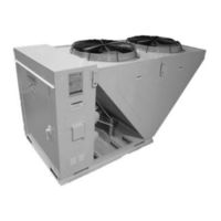
AAON CF Series Installation Operation & Maintenance (74 pages)
Condenser and Condensing Units
Brand:
AAON
| Category:
Heat Pump
| Size: 4.4 MB
Table of Contents
Table of Contents
2
AAON CF Series Features and Options Introduction
5
Safety
6
CF Series Feature String Nomenclature
11
General Information
14
Codes and Ordinances
14
Receiving Unit
14
Storage
15
Wiring Diagrams
16
General Maintenance
16
Installation
17
Forklifting the Unit
17
Figure 1 - Forklifting a CF Series a Cabinet
17
Figure 2 - Forklifting a CF Series B and C Cabinet
17
Lifting the Unit
18
Locating the Unit
18
Table 1 -Clearances for Proper Operation
18
Table 2 - Clearances for Coil Pull
18
Figure 3 - Lifting Details and Orientation of a CF Series 9-70 Ton Condensing Unit
18
Figure 4 - Orientation of Series 2-7 Ton Condensing Unit
18
Mounting Isolation
19
Access Doors
19
Low Ambient Operation
19
Fan Cycling Low Ambient
20
Variable Speed Low Ambient
20
Flooded Condenser Low Ambient
20
LAC Valve
20
Figure 5 - Adjustable Fan Cycling Switch
20
Condenser Flooding
21
Table 3 - Condenser Flooding
21
Figure 6 - Piping Schematic of Example System Using the LAC Valve
21
Refrigerant Piping
22
Determining Refrigerant Line Size
22
Liquid Line
23
Suction Line
24
Figure 7 - Double Suction Riser Construction
25
Discharge Line
26
Figure 8 - Heat Pump Piping Schematic of Suction Vapor Flow down in Double Riser
27
Figure 9 - Heat Pump Piping Schematic of Discharge Vapor Flow up in Double Riser
27
Hot Gas Bypass Line
28
Hot Gas Reheat
29
Figure 10 - Oil Return Line
29
Electrical
30
Startup
32
Compressor Operation
32
Variable Capacity Compressor Controller
33
Low Voltage Terminals
33
High Voltage Terminals
33
Figure 11 - Variable Capacity Compressor Controller
33
Table 4 - Demand Signal Vs. Compressor Capacity Modulation
34
Figure 12 - Compressor Controller Flash Code Details
34
Compressor Lockouts
35
Table 5 - Thermistor Temperature Vs. Resistance Values
35
Figure 13 - Adjustable Compressor Lockout
35
Figure 14 - Ambient Sensor Cover
35
Maintenance
36
General
36
Compressors
36
Refrigerant Filter Driers
36
Adjusting Refrigerant Charge
36
Table 6 - Max Filter Drier Pressure Drops
36
Table 7 - Acceptable Refrigeration Circuit Values
37
Lubrication
40
Condenser Tube Inspection
40
Maintenance Recommendations
40
Table 8 - R-410A Refrigerant Temperature-Pressure Chart
40
E-Coated Coil Cleaning
41
Service
43
Warranties
43
Replacement Parts
43
AAON - Longview Warranty, Service, and Parts Department
43
Split System Refrigerant Piping Diagrams
44
Figure 15 - A/C Split System Piping, Suction down
44
Figure 16 - A/C Split System Piping, Suction up
45
Figure 17 - A/C with LAC Split System Piping, Suction down
46
Figure 18 - A/C with LAC Split System Piping, Suction up
47
Figure 19 - A/C with Modulating Hot Gas Reheat Split System Piping, Suction down
48
Figure 20 - A/C with Modulating Hot Gas Reheat Split System Piping, Suction up
49
Figure 21 - A/C with Modulating Hot Gas Reheat Split + LAC System Piping, Suction down
50
Figure 22 - A/C with Modulating Hot Gas Reheat Split + LAC System Piping, Suction up
51
Figure 23 - A/C with Hot Gas Bypass Split System Piping, Suction down
52
Figure 24 - A/C with Hot Gas Bypass Split System Piping, Suction up
53
Figure 25 - A/C with Hot Gas Bypass + LAC Split System Piping, Suction down
54
Figure 26 - A/C with Hot Gas Bypass + LAC Split System Piping, Suction up
55
Figure 27 - A/C with Modulating Hot Gas Reheat and Hot Gas Bypass Split System Piping
56
Suction down
56
Figure 28 - A/C with Modulating Hot Gas Reheat and Hot Gas Bypass Split System Piping, Suction up
57
Figure 29 - A/C with Modulating Hot Gas Reheat and Hot Gas Bypass + LAC Split System
58
Piping, Suction down
58
Figure 30 - A/C with Modulating Hot Gas Reheat and Hot Gas Bypass + LAC Split System Piping, Suction up
59
Piping, Suction up
59
Figure 31 - Heat Pump Split System Piping, Suction down
60
Figure 32 - Heat Pump Split System Piping, Suction up
61
Figure 33 - Heat Pump with Modulating Hot Gas Reheat Split System Piping, Suction down
62
Figure 34 - Heat Pump with Modulating Hot Gas Reheat Split System Piping, Suction up
63
Figure 35 - Heat Pump with Hot Gas Bypass Split System Piping, Suction down
64
Figure 36 - Heat Pump with Hot Gas Bypass Split System Piping, Suction up
65
Figure 37 - Heat Pump with Modulating Hot Gas Reheat and Hot Gas Bypass Split System
66
Piping, Suction down
66
Figure 38 - Heat Pump with Modulating Hot Gas Reheat and Hot Gas Bypass Split System
67
Piping, Suction up
67
(Acp J00424)
74
Advertisement
AAON CF Series Installation Operation & Maintenance (90 pages)
Condenser and Condensing Units
Brand:
AAON
| Category:
Heat Pump
| Size: 6.96 MB
Table of Contents
Table of Contents
2
Figure 1 - Forklifting a CF Series a Cabinet
17
Figure 2 - Forklifting a CF Series B and C Cabinet
17
Table 1 - Clearances for Proper Operation
18
Table 2 - Clearances for Coil Pull
18
Figure 3 - Lifting Details and Orientation of a CF Series 9-70 Ton Condensing Unit
18
Figure 4 - Orientation of Series 2-7 Ton Condensing Unit
18
Figure 5 - CU Evacuation Connections
20
Figure 6 - CU Evacuation Connections
21
Table 3 - Acceptable Fin & Tube Refrigeration Circuit Values
23
Table 4 - Acceptable Microchannel Air-Cooled Condenser Coil Liquid Sub-Cooling Values
24
(Metric)
24
(Imperial)
24
Table 6 - R-410A Refrigerant Temperature-Pressure Chart (Metric)
26
Table 7 - R-410A Refrigerant Temperature-Pressure Chart (Imperial)
27
Table 8 - R-454B Refrigerant Temperature-Pressure Chart (Metric)
28
Table 9 - R-454B Refrigerant Temperature-Pressure Chart (Imperial)
29
F & Superheat=10
30
Table 11 - Charge to Flood Fin and Tube Condenser Coil for Ambient above 21.3°C (70°F)
31
Table 12 - Charge to Flood Microchannel Condenser Coil for Ambient above 21.3°C (70°F)
31
Table 13 - % Charge to Flood Condenser Coil for Ambient below 21.3°C (70°F)
31
Figure 7 - Adjustable Fan Cycling Switch
32
Figure 8 - LAC Piping Example
33
Figure 9 - Double Suction Riser Construction
36
Figure 10 - Heat Pump Piping Schematic of Cooling Mode in Double Riser
39
Figure 11 - Heat Pump Piping Schematic of Heating Mode in Double Riser
39
Figure 12 - Oil Return Line
41
Table 14 - Nameplate Voltage Markings & Tolerances
42
Table 15 - 35 KAIC Fuse Sizing
44
Table 16 - 65 KAIC Fuse Sizing
44
Figure 13 - Variable Capacity Compressor Controller
45
Table 17 - Demand Signal Vs. Compressor Capacity Modulation
46
Table 18 - Thermistor Temperature Vs. Resistance Values
47
Figure 14 - Compressor Controller Flash Code Details
47
Figure 16 - Ambient Sensor Cover
48
Figure 15 - Adjustable Compressor Lockout
48
Table 19 - Max Filter Drier Pressure Drops
49
Figure 17 - A/C Split System Piping, Suction down
57
Figure 18 - A/C Split System Piping, Suction up
58
Figure 19 - A/C with LAC Split System Piping, Suction down
59
Figure 20 - A/C with LAC Split System Piping, Suction up
60
Figure 21 - A/C with Modulating Hot Gas Reheat Split System Piping, Suction down
61
Figure 22 - A/C with Modulating Hot Gas Reheat Split System Piping, Suction up
62
Figure 23 - A/C with Modulating Hot Gas Reheat Split + LAC System Piping, Suction down
63
Figure 24 - A/C with Modulating Hot Gas Reheat Split + LAC System Piping, Suction up
64
Figure 25 - A/C with Hot Gas Bypass Split System Piping, Suction down
65
Figure 26 - A/C with Hot Gas Bypass Split System Piping, Suction up
66
Figure 27 - A/C with Hot Gas Bypass + LAC Split System Piping, Suction down
67
Figure 28 - A/C with Hot Gas Bypass + LAC Split System Piping, Suction up
68
Figure 29 - A/C with Modulating Hot Gas Reheat and Hot Gas Bypass Split System Piping
69
Suction down
69
Figure 30 - A/C with Modulating Hot Gas Reheat and Hot Gas Bypass Split System Piping
70
Suction up
70
Figure 31 - A/C with Modulating Hot Gas Reheat and Hot Gas Bypass + LAC Split System Piping, Suction down
71
Figure 32 - A/C with Modulating Hot Gas Reheat and Hot Gas Bypass + LAC Split System Piping, Suction up
72
Figure 33 - Heat Pump Split System Piping, Suction down
73
Figure 34 - Heat Pump Split System Piping, Suction up
74
Figure 35 - Heat Pump with Modulating Hot Gas Reheat Split System Piping, Suction down
75
Figure 36 - Heat Pump with Modulating Hot Gas Reheat Split System Piping, Suction up
76
Figure 37 - Heat Pump with Hot Gas Bypass Split System Piping, Suction down
77
Figure 38 - Heat Pump with Hot Gas Bypass Split System Piping, Suction up
78
Figure 39 - Heat Pump with Modulating Hot Gas Reheat and Hot Gas Bypass Split System Piping, Suction down
79
Figure 40 - Heat Pump with Modulating Hot Gas Reheat and Hot Gas Bypass Split System Piping, Suction up
80
Advertisement
Related Products
AAON CB-024
AAON CB-036
AAON CB-048
AAON CB-060
AAON CL SERIES
AAON ProFit WH Series
AAON ProFit WV Series
AAON RN Series
AAON RNA-011
AAON RNA-013
AAON Categories
Controller
Control Unit
Air Handlers
Heat Pump
Air Conditioner
More AAON Manuals
Login
Sign In
OR
Sign in with Facebook
Sign in with Google
Upload manual
Upload from disk
Upload from URL