Table of Contents
Advertisement
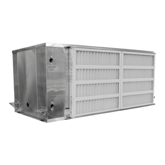
Horizontal Water-Source Heat Pump Unit
Installation, Operation
WARNING
If the information in this manual is not
followed exactly, a fire may result
causing property damage, personal
injury, or loss of life.
& Maintenance
WH Series
WARNING
QUALIFIED INSTALLER
Improper
installation,
alteration, service, or maintenance
can
cause
property
personal injury or loss of life. Startup
and service must be performed by a
Factory Trained Service Technician.
Keep a copy of this IOM with the unit.
adjustment,
damage,
Advertisement
Table of Contents

Related Manuals for AAON WH Series


Summary of Contents for AAON WH Series
- Page 1 WH Series Horizontal Water-Source Heat Pump Unit Installation, Operation & Maintenance WARNING QUALIFIED INSTALLER Improper installation, adjustment, WARNING alteration, service, or maintenance cause property damage, If the information in this manual is not personal injury or loss of life. Startup...
-
Page 3: Table Of Contents
Table of Contents AAON WH Series Features and Options Introduction ..............5 Safety .............................. 6 WSHP Series Feature String Nomenclature ................. 10 General Information ........................12 Codes and Ordinances ......................12 Receiving Unit .......................... 13 Storage ............................13 Direct Expansion (DX) Systems ....................13 Wiring Diagrams ........................ - Page 4 Table 10 - 006-012 WH Unit Series Filters (A Cabinet) .............. 52 Table 11 - 015-030 WH Series Unit Filters (B & C Cabinet) ............52 Table 12 – 036 & 042 WH Series Unit Filters (D Cabinet) ............53 Table 13 –...
-
Page 5: Aaon Wh Series Features And Options Introduction
AAON WH Series Features and Options Introduction Energy Efficiency Installation and Maintenance Direct Drive Supply Fan Tool-Less Access Panels • • Scroll or Rotary Compressor Optional Bottom Service Access • • Closed Cell Neoprene Foam Cabinet Color-Coded Wiring Wiring •... -
Page 6: Safety
Safety Attention must be paid to the following statements: NOTE - Notes are intended to clarify the unit installation, operation and maintenance. CAUTION - Caution statements are given to prevent actions that may result in equipment damage, property damage, or personal injury. WARNING - Warning statements are given to prevent actions that could result in equipment damage, property damage, personal injury or death. - Page 7 AAON Inc. property damage. warranties and the heat exchanger manufacturer’s warranties. Improper servicing could result in dangerous operation, serious injury, death, or property damage.
- Page 8 Only equipment as a result of water qualified licensed electrician freezing is excluded from coverage individual properly trained in handling under AAON warranties and the heat live electrical components must exchanger manufacturer warranties. perform these tasks. Standard NFPA-70E,...
- Page 9 1. READ THE ENTIRE INSTALLATION, 3. The unit is for indoor use only. See OPERATION AND MAINTENANCE General Information section for more MANUAL. OTHER IMPORTANT unit information. SAFETY PRECAUTIONS PROVIDED THROUGHOUT THIS 4. Every unit has a unique equipment MANUAL. nameplate with electrical, operational, unit clearance...
-
Page 10: Wshp Series Feature String Nomenclature
WSHP Series Feature String Nomenclature Unit Configuration Accessory Options WH A - 024 - C - 0 - 3 - 1 - 0 0 : 0 0 - 0 A - 0 0 - 0 0 - 0 0 0 0 0 - 0 0 0 0 0 MODEL OPTIONS C = 208-230V/1Φ/60Hz Generation and Orientation... - Page 11 B = Non-Fused Service Disconnect - 60 Amp 0 = Standard - Sheet Metal Pallet with Forklift Slots D = 5 KAIC Standard / 100 KAIC w/ Field Installed and AAON Blue Shrink Wrap Fusing E = 100 KAIC Fusing...
-
Page 12: General Information
Codes and Ordinances WSHP Series units have been tested and certified, by ETL, in accordance with UL AAON WH Series Water-Source Heat Safety Standard 1995/CSA C22.2 No. 236. Pump units (WSHP) are designed for indoor installation only. Units are assembled, System must be sized in accordance with the wired, charged and run-tested at the factory. -
Page 13: Receiving Unit
Always control the unit from the thermostat, manufacturer’s consent may void the or control panel, never at the main power product warranty. Contact the AAON supply, except for emergency or complete Warranty Department for assistance with shutdown of the unit. -
Page 14: Wiring Diagrams
(factory provided) and 3/8” washers (field provided) AAON equipment has been designed for and as shown in Figure 3. quick and easy installation. Before startup of the unit, check the supply blower and remove the foam shipping block... -
Page 15: Condensate Drain Piping
Verify the top of the vibration grommet is inserted into (or through) the hole provided in the hanger bracket, as pointed out in Figure 4. Condensate Drain Figure 5 - Condensate Drain Piping CAUTION Emergency drain recommended for all applications where a risk of water damage to Figure 4 - Vibration Grommet Installation surrounding structure or furnishings. -
Page 16: Figure 6 - Drain Trap
up due to air being pulled up through the CAUTION condensate drain piping. Unit must not be operated without p- Condensate drain trapping and piping must traps. Failure to install a p-trap may conform to all applicable governing codes. result in overflow of condensate water. -
Page 17: Figure 7 - Wh Series Unit Orientation (Right Return Unit Shown)
120, 150 *Note: If bottom service access is not available, optional dimensions are required. Straight Discharge Water Connections Air Intake (Filters) Discharge End Discharge (Optional) Air Intake (Filters) Straight Discharge Figure 7 - WH Series Unit Orientation (Right Return Unit Shown) -
Page 18: Blower Assembly Removal - Side Access
Blower Assembly Removal – Side Access � 1) Using ” socket, remove shipping screw on the outside of the right or discharge side of the unit as shown in the figure below. Figure 8 - Blower Assembly with Captive Panel 2) Remove the side blower access panel using the panel handle and lift the panel upwards about ½”... -
Page 19: Discharge Modification
Discharge Modification Note: Installing blower panel upside down The AAON WSHP discharge direction can will result in damage to the unit. be selected in ECat and is also designed so that the discharge direction can be field modified if needed. -
Page 20: Lifting And Handling The Unit
panel upside down will result in damage to For A Cabinet (009 & 012) the unit.) Remove the blower assembly as outlined in the “Blower Assembly Removal – Side Access” section before modifying the discharge. Once complete, proceed to the following: �... -
Page 21: Horizontal Unit Bottom Access
Bottom clearance required for the unit can While leaving the bottom access panel in be found on Table 2 - WSHP WH Series this position is acceptable for most service / Clearances. maintenance conditions, occasionally it will... -
Page 22: Blower Assembly Removal - Bottom Access
2) Open the bottom access panel section as described in the “Horizontal Unit Bottom Access” section. 3) Remove the five (5) spade connectors on the blower motor as shown in Figure 13. At this point, the end that was just pulled will be low enough to clear the bottom access hole and slide the panel out of the unit. -
Page 23: Blower Motor And Fan Access
2) Pull the motor and blower up and out of the blower assembly. 6) Once the blower assembly is clear of the blower panel, firmly pull the blower 3) Separate the motor from the blower sub assembly down and away from the unit. assembly, place the sub assembly (motor side down) and remove the set screw as shown below. - Page 24 Failure of the refrigerant-to-water heat exchanger as a result of chemical corrosion Freezing Water in the Heat Exchanger is excluded from coverage under AAON This product contains one refrigerant-to- warranties heat exchanger water heat exchanger. A refrigerant-to-water manufacturer warranties.
- Page 25 Set the glycol percentage to the closest option available, rounding down if needed. The option selected will reset the Leaving Water Temperature safety for the unit. AAON will not be responsible for frozen coaxial coils due to improper selection of...
- Page 26 CAUTION CAUTION PVC (Polyvinyl Chloride) and CPVC Installing contractor is responsible for (Chlorinated Polyvinyl Chloride) are properly sizing and installing water vulnerable attack certain system components. Improper fluid chemicals. Polyolester (POE) oils flow valves, piping, used with R-410A other improper pump operation may result refrigerants, even in trace amounts, in unacceptable unit operation and in a PVC or CPVC piping system will...
-
Page 27: Electrical
Field provided and installed water treatment Table 4 - Nameplate Voltage Markings program must be compatible with stainless Nameplate Min/Max steel, copper, aluminum, ABS plastic, and Voltage Feature Voltage PVC. Batch feed processes must never be Marking used as concentrated chemicals can cause 230V/1Φ/60HZ 197/252 corrosion. - Page 28 All wiring beyond this knockouts and/or capped pre-cut holes have point has been completed by AAON and been provided. Horizontal units have been cannot be modified without effecting the provided with both high and low voltage unit’s agency/safety certification.
-
Page 29: How To Connect To Wh Series Disconnect
Supply fan motors must all be checked by a qualified service technician at startup and any How to Connect to WH Series Disconnect wiring alteration must only be made at the unit power connection. 30 Amp Disconnect 1) Remove compressor panel Wire control signals to the unit’s low... -
Page 30: Figure 15 - Disconnect Terminals
3) Connect power to terminals of the 3) Remove the four screws behind the disconnect switch. Connecting the field faceplate with Phillips head wires (copper conductors only) to screwdriver release switch terminals L1, L2, and L3 of the terminal block disconnect switch using the screw terminal connections. -
Page 31: Figure 19 - Filter Access Doors
Thermostat Control Wiring Take the total wire distance allowable and If a thermostat is used for unit control, divide by the number of wires to be locate thermostat on an inside wall 4-5 feet connected. This indicates the distance above the floor where it will not be allowable for that size wire. -
Page 32: Figure 20 - Filter Rack Closed With Clip
Filter Pull Setup Do not operate the unit without filters in place. Each unit has a filter pull located in the filter section of the unit. The filter pull must be setup prior to installing or changing the filters. If side access to the filters is desired, then no further action is required. -
Page 33: Duct Connection
4. Reinstall the filters, taking note of the waterside economizer coil via an internal correct orientation with regard to 3-way valve. airflow. During mechanical cooling only mode of 5. If necessary, close the filter access door operation water flows around the waterside and press the fastener clip firmly until economizer coil... -
Page 34: Startup
Startup the air volume specified according to unit size and job requirements. (See back of the manual for startup form) Operation Limits Cooling Heating Min. Entering Air 65°F 55°F Max Entering Air 100°F 80°F Min. Entering Water 68°F 50°F Max Entering Water 104°F 86°F Min. -
Page 35: Adjusting Refrigerant Charge
on the control board. The higher fan speed CAUTION is achieved by connecting Y from the thermostat to Y2 on the control board. Due to the charge-critical nature of these units, charge must only be Motor Tap RPMs adjusted if absolutely necessary. PSC Tap Speed Adjusting the charge of a system in the field... - Page 36 Convert the pressure obtained to a saturated Table 6 - Acceptable Refrigeration Circuit temperature using the appropriate refrigerant Values at AHRI ISO 13256 WLHP temperature-pressure chart. Conditions Water-Source Heat Pump Subtract measured liquid line Sub-Cooling 4-8°F temperature from the saturated temperature Superheat 8-15°F to determine the liquid sub-cooling.
- Page 37 Table 7 - R-410A Refrigerant Temperature-Pressure Chart °F PSIG °F PSIG °F PSIG °F PSIG °F PSIG 78.3 134.7 213.7 321.0 463.2 80.0 137.2 217.1 325.6 469.3 81.8 139.7 220.6 330.2 475.4 83.6 142.2 224.1 334.9 481.6 85.4 144.8 227.7 339.6 487.8 87.2...
-
Page 38: Operation
Silver Controller contains 0 to 95% RH non-condensing functionality required to operate the basic configuration of AAON WH Series units. Mounting & Dimensions The controller requires commands from a Mounting standard heat pump room thermostat and has Board is mounted via four shoulder eyelets outputs to control a supply fan, compressor, located on the corners of the circuit board. - Page 39 Pluggable Screw Terminal Block H5 PINK = Not used 24V = 24VAC power output for thermostat. BROWN = Condensate drain pan sensor NS_OV = Night setback override input. input. Input requires 24VAC to activate. GREEN = Low pressure switch. Input O = Thermostat input for reversing valve requires a normally closed switch.
-
Page 40: Figure 25 - Pioneer Silver Controller Layout
Figure 25 – Pioneer Silver Controller Layout Sequences of Operation Compressor Operation Supply Fan Operation The compressor will enable upon receiving a Supply fan will enable upon receiving a 24VAC input on the “Y” terminal or a 24VAC input on the “G” terminal or a call 24VAC input on the “TH_NS”... - Page 41 Reversing Valve Operation override terminal “NS_OV”. Once the The reversing valve will enable if the override signal is received, night setback controller receives a 24VAC input on the will be overridden for 2 hours even if the “O” terminal and the compressor has been signal is removed.
- Page 42 Table 8 - LED Diagnostic Codes 5%. Once the fault is cleared the controller will activate a random start delay. This Number Fault alarm will disable the compressor, the of LED supply fan, and the reversing valve. Flashes High Discharge Pressure Leaving Water Temperature Alarm Emergency Shutdown To prevent freezing of the liquid heat...
- Page 43 Table 9 - Glycol Percentage Setpoints Leaving Water Leaving Water Switch 1 Switch 2 Glycol Temperature Temperature Position Position Percentage Alarm Alarm Activation Deactivation 35°F 40°F 10%* 30°F 35°F 23°F 28°F 15°F 20°F *Setting not recommended. 20% or more glycol solution is required if ambient temperatures are expected to fall below freezing or if the loop water temperature is below 50°F while operating in the heating mode.
- Page 44 High Discharge Pressure Alarm The high discharge pressure alarm will enable if the high pressure switch opens. This alarm will disable the compressor but allow the supply fan to operate. Low Suction Pressure Alarm The low suction pressure alarm will activate and turn the compressor off if the low suction pressure switch is open for 10 seconds.
-
Page 45: Aaon Wshp Pioneer Silver Expansion Board
AAON WSHP Pioneer Silver Expansion Mounting & Dimensions Board Mounting Part Number: V75410 Board is mounted via four shoulder eyelets located on the corners of the circuit board. Description The Water-Source Heat Pump Pioneer Dimensions Silver Expansion Board used 6.5” x 4.0”... -
Page 46: Figure 26 - Pioneer Silver Expansion Board Layout
Quick Disconnect Terminals P12 - AO1 = EC Supply Speed (+VDC), P1 - Not Used 0-10VDC P2 - 24VAC = 24VAC Power P13 - COM = EC Supply Speed (-VDC) P3 - COM = 24VAC Common P14 - FAN HIGH = 24VAC Fan High P4 - HEAT 2 Enable = 24VAC output Speed output P5 - COM = Heat 2 Common... - Page 47 Dip Switch SW1 Fan-Speed Dehumidification Selections Pos 9 Fan-Speed Dehum Disabled Fan-Speed Dehum Enabled POS 1 through 8 are not currently used. Dip Switch SW2 1. Waterside Economizer Enable Pos 1 WSE Disabled WSE Enabled 2. Waterside Economizer Temperature Enable Setpoint Selection Pos 2 Pos 3 Pos 4...
- Page 48 Additional Sequence of Operations enable for 5 seconds before the compressor is started. Supply Fan Operation The supply fan will enable upon receiving a The compressor has a minimum on time and 24VAC input on the “G” terminal or upon a a minimum off time of 180 sec and 120 sec call for compressor operation, unless an respectively to prevent short cycling.
-
Page 49: Maintenance
disabled, and compressor cooling will be Hot Gas Reheat Dehumidification For Hot Gas Reheat Dehumidification, utilized. switch 1, position 9 must be set to “OFF”. Maintenance Hot Gas Reheat Dehumidification Mode is See back of the manual for maintenance log. enabled based on a 24VAC input to the “DH”... -
Page 50: Supply Fans
Cleaning microchannel coils is necessary in all locations. In some locations it may be #1 Simple Green necessary to clean the coils more or less Simple Green is available from AAON Parts often than recommended. In general, a Supply (Part#... -
Page 51: Filter Replacement
2. With a pump sprayer filled with a mix of AAON testing has determined that unless a 4 parts water to 1 part Simple Green, chemical has a neutral pH (6-8) it must not spray the air inlet face of the coil. Be be used. -
Page 52: Replacement Parts
E & 0 Pleated, MERV 8 (1) 24” x 10” x 1” Pleated, MERV 11 Pleated, MERV 13 Table 11 - 015-030 WH Series Unit Filters (B & C Cabinet) Feature 3B Quantity/Size (W x H x D) Type A & 0 (2) 16”... - Page 53 Table 12 – 036 & 042 WH Series Unit Filters (D Cabinet) Feature 3B Quantity/Size (W x H x D) Type A & 0 (2) 20” x 20” x 2” Pleated, MERV 8 Pleated, MERV 11 (2) 20” x 20” x 4”...
-
Page 54: Appendix A - Heat Exchanger Corrosion Resistance
Appendix A - Heat Exchanger Corrosion Resistance Potential Range for Copper Heat Range for Cupro-Nickel Chemical(s) or Condition Problem Exchangers Heat Exchangers Calcium & Magnesium Scaling Less than 350 ppm Less than 350 ppm Carbonate pH Range Total Dissolved Solids Less than 1000 ppm Less than 1500 ppm Ammonia, Ammonium... - Page 55 WH Series Startup Form Job Name:_______________________________________________ Date:______________ Address:______________________________________________________________________ ______________________________________________________________________________ Model Number:_________________________________________________________________ Serial Number:_____________________________________________ Tag:_______________ Startup Contractor:______________________________________________________________ Address:______________________________________________________________________ _______________________________________________________ Phone:______________ Pre Startup Checklist Installing contractor must verify the following items. 1. Is there any visible shipping damage? 2. Is the unit level? 3.
- Page 56 Supply Fan Assembly Alignment Check Rotation Nameplate Amps________ Number Compressors/DX Cooling Only connect gauges for troubleshooting Check Rotation Head Suction Number Pressure Pressure PSIG PSIG Refrigeration System 1 - Cooling Mode Due to the charge-critical nature of these units, charge must only be adjusted if absolutely necessary Saturated Line...
- Page 57 This log must be kept with the unit. It is the responsibility of the owner and/or maintenance/service contractor to document any service, repair or adjustments. AAON Service and Warranty Departments are available to advise and provide phone help for proper operation and replacement parts.
- Page 58 April 2017 Heat Exchanger Corrosion Resistance updated. Blower Motor and Fan Access updated. May 2017 Updated the Supply Fan Operation section for the AAON WSHP Pioneer Silver Expansion Board. August 2017 Feature 2- Supply Fan nomenclature corrected; B = Standard Fan + ECM Motor. Feature 3A –...
-
Page 60: V81280 · Rev. F · 200721
Parts: For replacement parts please contact your local AAON Representative. It is the intent of AAON to provide accurate and current product information. However, in the interest of product improvement, AAON reserves the right to change pricing, specifications, and/or design of its product without notice, obligation, or liability.