Table of Contents
Advertisement
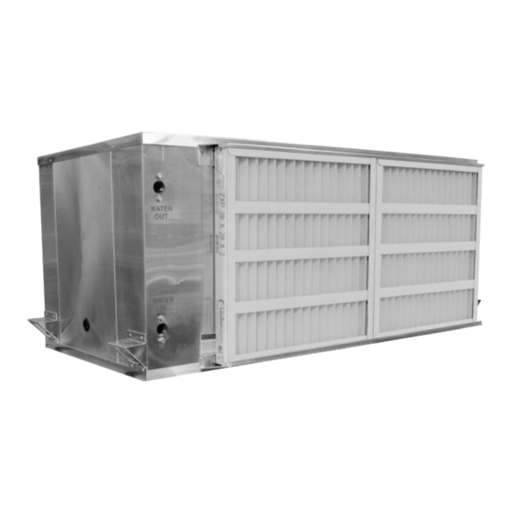
Horizontal Water-Source Heat Pump Unit
Installation, Operation
WARNING
If the information in this manual is not
followed exactly, a fire may result
causing property damage, personal
injury, or loss of life.
& Maintenance
WH Series
WARNING
QUALIFIED INSTALLER
Improper
installation,
alteration, service, or maintenance
can
cause
property
personal injury or loss of life. Startup
and service must be performed by a
Factory Trained Service Technician.
A copy of this IOM should be kept
with the unit.
adjustment,
damage,
Advertisement
Table of Contents

Related Manuals for AAON WH Series


Summary of Contents for AAON WH Series
- Page 1 WH Series Horizontal Water-Source Heat Pump Unit Installation, Operation & Maintenance WARNING QUALIFIED INSTALLER Improper installation, adjustment, alteration, service, or maintenance cause property damage, WARNING personal injury or loss of life. Startup and service must be performed by a If the information in this manual is not Factory Trained Service Technician.
-
Page 2: Table Of Contents
Table of Contents AAON WSHP Series Features and Options Introduction .............. 4 Safety .............................. 5 WSHP Series Feature String Nomenclature ................... 9 General Information ........................11 Codes and Ordinances ......................11 Receiving Unit .......................... 12 Storage ............................12 Direct Expansion (DX) Systems ....................12 Wiring Diagrams ........................ - Page 3 Table 9 – 006, 009, & 012 WH Unit Series Filters (A Cabinet) ........... 49 Table 10 – 015, 018, 024, & 030 WH Series Unit Filters (B & C Cabinet) ......... 50 Table 11 – 036 & 042 WH Series Unit Filters (D Cabinet)............50 Table 12 –...
-
Page 4: Aaon Wshp Series Features And Options Introduction
AAON WSHP Features and Options Introduction Energy Efficiency Installation and Maintenance • Direct Drive Forward Curved Supply Fan • Tool-Less Access Panels Scroll or Rotary Compressor Bottom Service Access • • • Closed Cell Neoprene Foam or 1” Foil •... -
Page 5: Safety
Safety Attention should be paid to the following statements: NOTE - Notes are intended to clarify the unit installation, operation and maintenance. CAUTION - Caution statements are given to prevent actions that may result in equipment damage, property damage, or personal injury. WARNING - Warning statements are given to prevent actions that could result in equipment damage, property damage, personal injury or death. - Page 6 Failure of the condenser as a result Failure to follow safety warnings of chemical corrosion is excluded exactly could result in dangerous from coverage under AAON Inc. operation, serious injury, death or warranties and the heat exchanger property damage. manufacturer’s warranties.
- Page 7 Only freezing in the condenser is excluded qualified licensed electrician from coverage under AAON individual properly trained in handling warranties and the heat exchanger live electrical components shall manufacturer warranties. perform these tasks. Standard NFPA-70E,...
- Page 8 1. READ THE ENTIRE INSTALLATION, 3. The unit is for indoor use only. See OPERATION AND MAINTENANCE General Information section for more MANUAL. OTHER IMPORTANT unit information. SAFETY PRECAUTIONS PROVIDED THROUGHOUT THIS 4. Every unit has a unique equipment MANUAL. nameplate with electrical, operational, unit clearance...
-
Page 9: Wshp Series Feature String Nomenclature
WSHP Series Feature String Nomenclature Unit Configuration Accessory Options WH A - 024 - C - 0 - 1 - 1 - 0 0 0 : 0 0 - 0 A - 0 0 - 0 0 - 0 0 0 0 0 - 0 0 0 0 0 MODEL OPTIONS Generation and Orientation Efficiency Level... - Page 10 B = On/Off Hot Gas Reheat Dehumidification 12: Shipping Options 0 = Standard - Sheet Metal Pallet with Forklift Slots 5: Service Disconnect and AAON Blue Shrink Wrap 0 = Standard - None A = Non-Fused Service Disconnect 13: Blank...
-
Page 11: General Information
Codes and Ordinances General Information WSHP Series units have been tested and certified, by ETL, in accordance with UL AAON WH Series Water-Source Heat Safety Standard 1995/CSA C22.2 No. 236. Pump units (WSHP) are designed for indoor installation only. Units are assembled, System should be sized in accordance with wired, charged and run-tested at the factory. -
Page 12: Receiving Unit
Contact the supply, except for emergency or complete AAON Warranty Department for assistance shutdown of the unit. with handling damaged goods, repairs, and freight claims: (918) 382-6400. -
Page 13: Wiring Diagrams
(4) vibration grommets and 3/8” inside the control compartment panel. washers provided and as shown in Figure 3. Installation Threaded Rod AAON equipment has been designed for (Field Provided) quick and easy installation. Vibration Grommet Before startup of the unit, remove the foam... -
Page 14: Condensate Drain Piping
CAUTION Emergency drain recommended for all applications where a risk of water damage to surrounding structure or furnishings. Refer to local codes. Floor Mounted Units Make sure the unit is level and mounted on a field supplied platform with a minimum Figure 4 - Vibration Grommet Installation height to allow for proper depth of the condensate line p-trap. -
Page 15: Figure 6 - Drain Trap
Draw-through cooling coils will have a negative static pressure in the drain pan area. This will cause an un-trapped drain to back up due to air being pulled up through the condensate drain piping. Condensate drain trapping and piping should conform to all applicable governing codes. -
Page 16: Table 1 - Wshp Wh Series Clearances
072, 084 *Note: If bottom access is not available, optional dimensions become required. Straight Discharge Water Connections Air Intake (Filters) Discharge End Discharge (Optional) Air Intake (Filters) Straight Discharge Figure 7 - WH Series Unit Orientation (Right Return Units Shown) -
Page 17: Blower Assembly Removal - Side Access
Blower Assembly Removal – Side Access 1) Using a ¼” socket drive, remove the shipping screw on the outside of the right or discharge side of the unit as shown in the figure below. Figure 8 - Blower Assembly with Captive Panel 2) Remove the side blower access panel using the panel handle and lift the panel... -
Page 18: Discharge Modification
“Blower Assembly Removal – Side Discharge Modification Access” section, step 2. The AAON WSHP discharge direction can be selected in ECat and is also designed so 5) Swap the two panels keeping note of that the discharge direction can be field which side is up. -
Page 19: Lifting And Handling The Unit
Ensure both the blower panel and side To access the bottom panel, use a *flat* access panels are installed correctly as head screw driver to remove the screws that outlined in the “Blower Assembly Removal hold the panel in place; –... -
Page 20: Blower Assembly Removal - Bottom Access
To do this, grasp both sides of the panel and using a moderate amount of force, pull the compressor side of the panel, approximately 30 degrees, towards the opposite side of the unit. Figure 12 - Shipping Screw 2) Open the bottom access panel section as described in the “Blower Assembly Removal –... -
Page 21: Blower Motor And Fan Access
2) Pull the motor and blower up and out of 6) Once the blower assembly is clear of the the blower assembly. blower panel, firmly pull the blower assembly down and away from the unit. Blower Motor and Fan Access To access the blower motor and fan, first 3) Separate the motor from the blower sub remove the blower assembly as outlined in... -
Page 22: Refrigerant-To-Water Heat Exchanger Water Piping
AAON warranties and the heat exchanger Refrigerant-to-Water Heat Exchanger Water Piping manufacturer warranties. Open Loop Applications This product contains refrigerant-to-water WARNING heat exchanger made of cupronickel or copper and is subject to severe corrosion and OPEN LOOP APPLICATIONS failure when exposed to chlorides. -
Page 23: Table 2 - Glycol Freezing Points
AAON will not be responsible for frozen freezing in the condenser is excluded from coaxial coils due to improper selection of coverage under AAON warranties and the glycol percentage. See Leaving Water heat exchanger manufacturer warranties. -
Page 24: Table 3 - Condenser Water Connections
Water Piping Condenser water pump must be field sized and installed between the cooling tower or WARNING geothermal wellfield and self-contained unit. System should be sized in accordance with WATER PRESSURE the ASHRAE Handbook. Use engineering Prior to connection of condensing guidelines to maintain equal distances for water supply, verify water pressure is supply and return piping and limit bend... -
Page 25: Electrical
of the condenser water must be controlled. with single point power wiring connections. All make-up water has minerals in it and as A complete set of unit specific wiring the water is evaporated in the cooling tower, diagrams, showing factory and field wiring these minerals remain. - Page 26 All wiring beyond this knockouts and/or capped pre-cut holes have point has been completed by AAON and been provided. Horizontal units have been cannot be modified without effecting the provided with both high and low voltage unit’s agency/safety certification.
-
Page 27: Table 4 - Control Wiring
following chart to determine the allowable CAUTION wiring distances. Rotation must be checked on all Table 4 - Control Wiring MOTORS AND COMPRESSORS of Wire Size (Stranded) Total Wire Distance three phase units. Supply fan motors - Copper Conductors Allowable should all be checked by a qualified Only service technician at startup and any... -
Page 28: Optional 4-Sided Air Filter Rack Setup
Optional 4-Sided Air Filter Rack Setup The access door handles and filter pull must be set-up prior to installing or changing the filters. Figure 14 - Filter access Doors Filter Access Door Handles Set-up amount of force, bend the handle away 1. -
Page 29: Figure 17 - Filter Pull
Note: Caution should be given not to Note: The fastener clip will remain over bend handles, as this may fracture captive in the filter frame access door or break the material. to streamline filter maintenance and prevent hardware loss. 2. Repeat this process on all access door handles. -
Page 30: Duct Connection
Note: Caution should be given that firmly until the fastener is locked into filters are clear of access holes so that position as shown in Figure 16. filter damage does not occur. See Figure 20. Duct Connection Attach duct to flanges provided on the unit. 5. -
Page 31: Startup
Waterside economizer coil condensate Startup drains into evaporator coil drain pan. See (See back of the manual for startup form) the previous section on evaporator coil condensate drain piping. WARNING Mineral content of the condenser water must be controlled. All make-up water has Improper installation, adjustment,... -
Page 32: Fan Air Flow Adjustment
Motor Tap RPMs PSC Tap Speed High 1200 Black Blue Figure 23 - WSHP Series Supply Fan Note: RPMs are approximate, and will vary slightly depending on TSP across the blower Fan Air Flow Adjustment assembly A specific air volume is delivered by the PSC or Electronically Commutated Motors Filters (ECM) fans. -
Page 33: Table 5 - Acceptable Refrigeration Circuit Values At Ahri Iso 13256 Wlhp Conditions
Before Charging Read gauge pressure at the suction line close Unit being charged must be at or near full to the compressor. load conditions before adjusting the charge. Convert the pressure obtained to a saturated Units equipped with hot gas reheat must be temperature using the appropriate refrigerant charged with the hot gas reheat valves temperature-pressure chart. - Page 34 Adjusting Sub-Cooling Superheat Temperatures The system is overcharged if the sub-cooling temperature is too high and the evaporator is fully loaded (low loads on the evaporator result in increased sub-cooling) and the evaporator superheat within temperature range as shown in the table above (high superheat results in increased sub-cooling).
-
Page 35: Table 6 - R-410A Refrigerant Temperature-Pressure Chart
Table 6 - R-410A Refrigerant Temperature-Pressure Chart °F PSIG °F PSIG °F PSIG °F PSIG °F PSIG 78.3 134.7 213.7 321.0 463.2 80.0 137.2 217.1 325.6 469.3 81.8 139.7 220.6 330.2 475.4 83.6 142.2 224.1 334.9 481.6 85.4 144.8 227.7 339.6 487.8 87.2... -
Page 36: Operation
Silver Controller contains 0 to 95% RH non-condensing functionality required to operate the basic configuration of AAON WH Series units. Mounting & Dimensions The controller requires commands from a Mounting standard heat pump room thermostat and has Board should be mounted via four shoulder... - Page 37 Pluggable Screw Terminal Block H5 PINK = Not used 24V = 24VAC power output for thermostat. BROWN = Condensate drain pan sensor NS_OV = Night setback override input. input. Input requires 24VAC to activate. GREEN = Low pressure switch. Input O = Thermostat input for reversing valve requires a normally closed switch.
-
Page 38: Figure 24 - Pioneer Silver Controller Layout
Figure 24 – Pioneer Silver Controller Layout Sequences of Operation Compressor Operation The compressor will enable upon receiving a Supply Fan Operation 24VAC input on the “Y” terminal or a Supply fan will enable upon receiving a 24VAC input on the “TH_NS” terminal if in 24VAC input on the “G”... - Page 39 Reversing Valve Operation override terminal “NS_OV”. Once the The reversing valve will enable if the override signal is received, night setback controller receives a 24VAC input on the will be overridden for 2 hours even if the “O” terminal and the compressor has been signal is removed.
-
Page 40: Table 7 - Led Diagnostic Codes
Table 7 - LED Diagnostic Codes Leaving Water Temperature Alarm The leaving water temperature alarm will Number Fault trigger if the leaving water temperature of LED becomes too cold. The glycol percentage Flashes DIP switch “S1” located in the center of the High Discharge Pressure control board... - Page 41 Lock Out Alarms Low Suction Pressure Alarm The following alarms will not automatically The low suction pressure alarm will enable reset themselves on the fault condition if the low pressure switch opens for more clears. than 10 seconds. This alarm will disable the compressor but allow the supply fan to For these alarms to clear one of the operate.
-
Page 42: Aaon Wshp Pioneer Silver Expansion Board
AAON WSHP Pioneer Silver Expansion Mounting & Dimensions Mounting Board Part Number: V75410 Board should be mounted via four shoulder eyelets located on the corners of the circuit Description board. The Water-Source Heat Pump Pioneer Silver Expansion Board used Dimensions conjunction with the Water-Source Heat 6.5”... -
Page 43: Figure 25 - Pioneer Silver Expansion Board Layout
Quick Disconnect Terminals P12 - AO1 = EC Supply Speed (+VDC), P1 - Not Used 0-10VDC P2 - 24VAC = 24VAC Power P13 - COM = EC Supply Speed (-VDC) P3 - COM = 24VAC Common P14 - FAN HIGH = 24VAC Fan High P4 - HEAT 2 Enable = 24VAC output Speed output P5 - COM = Heat 2 Common... - Page 44 Dip Switch SW1 Simple Dehumidification Selections Pos 9 Simple Dehum Disabled Simple Dehum Enabled POS 1 through 8 are not currently used. Dip Switch SW2 1. Waterside Economizer Enable Pos 1 WSE Disabled WSE Enabled 2. Waterside Economizer Temperature Enable Setpoint Selection Pos 2 Pos 3 Pos 4...
- Page 45 Additional Sequence of Operations includes built-in compressor inter-stage delays. Supply Fan Operation The supply fan will enable upon receiving a All alarms will disable the compressor. 24VAC input on the “G” terminal or upon a call for compressor operation, unless an With a “Y1”...
-
Page 46: Maintenance
Hot Gas Reheat Dehumidification fans, evaporator coils and air filters should For Hot Gas Reheat Dehumidification, be inspected monthly. switch 1, position 9 must be set to “OFF”. WARNING The compressor is enabled at full capacity “Y2” when dehumidification mode is Improper installation, adjustment,... -
Page 47: Supply Fans
Supply Fan Lubrication performance and safety and are the only All original blower motors and bearings are chemicals that AAON will warrant as furnished with factory lubrication. Some correct for cleaning microchannel coils. applications will require that bearings be re- There are three procedures that are outlined lubricated periodically. - Page 48 #1 Simple Green 1. Rinse the coil completely with water. Simple Green is available from AAON Parts Use a hard spray but be careful not to Supply (Part# T10701) bend or damage the fins. A spray that is biodegradable with a neutral 6.5 pH.
-
Page 49: Filter Replacement
See Optional 4-Sided Air Filter Rack Set-up prior to maintenance of the filter rack. See Filter Information section for reference to the correct size and quantity of filters. Replacement Parts Parts for AAON equipment may be obtained contacting your local AAON representative. -
Page 50: Table 10 - 015, 018, 024, & 030 Wh Series Unit Filters (B & C Cabinet)
Table 10 – 015, 018, 024, & 030 WH Series Unit Filters (B & C Cabinet) Feature 3B Quantity/Size (W x H x D) Type 16” x 16” x 2” Filters Must Be Field Installed (2) 16” x 16” x 2”... -
Page 51: Appendix A - Heat Exchanger Corrosion Resistance
Appendix A - Heat Exchanger Corrosion Resistance The resistance guide below provides the corrosion resistance of stainless steel type AISI 316 and pure Copper (99.9%) in water, to a number of important chemical factors. The actual corrosion is a very complex process influenced by many different factors in combination. Explanations: + Good resistance under normal conditions 0 Corrosion problems may occur especially when more factors are valued 0 - Use is not recommended... - Page 52 Water Concentration Time Limits - AISI Copper Nickel Containing (mg/l or ppm) Analyze Before Alloy Alloy Total Hardness 4.0-8.5 No Limit (°dH) < 100 Nitrate (NO No Limit > 100 < 0.2 Iron (Fe) No Limit > 0.2 < 0.2 Aluminum (Al) No Limit >...
- Page 53 WH/WV Series Startup Form Job Name:_______________________________________________ Date:______________ Address:______________________________________________________________________ ______________________________________________________________________________ Model Number:_________________________________________________________________ Serial Number:_____________________________________________ Tag:_______________ Startup Contractor:______________________________________________________________ Address:______________________________________________________________________ _______________________________________________________ Phone:______________ Pre Startup Checklist Installing contractor should verify the following items. 1. Is there any visible shipping damage? 2. Is the unit level? 3.
- Page 54 Supply Fan Assembly Alignment Check Rotation Nameplate Amps________ Number Compressors/DX Cooling Only connect gauges for troubleshooting Check Rotation Head Suction Number Pressure Pressure PSIG PSIG Refrigeration System 1 - Cooling Mode Due to the charge-critical nature of these units, charge should only be adjusted if absolutely necessary Saturated Line...
- Page 55 This log must be kept with the unit. It is the responsibility of the owner and/or maintenance/service contractor to document any service, repair or adjustments. AAON Service and Warranty Departments are available to advise and provide phone help for proper operation and replacement parts.
- Page 56 Parts: For replacement parts please contact your local AAON Representative. It is the intent of AAON to provide accurate and current product information. However, in the interest of product improvement, AAON reserves the right to change pricing, specifications, and/or design of its product without notice, obligation, or liability.