
Related Manuals for Omega DP24-E


Summary of Contents for Omega DP24-E
- Page 1 User’ s Guide RoHS 2 Compliant Shop on line at ® ® omega.com e-mail: info@omega.com For latest product manuals www.omegamanual.info DP24-E Process Meter...
- Page 2 OMEGA will add the mark to every appropriate device upon certification. The information contained in this document is believed to be correct but OMEGA Engineering, Inc. accepts no liability for any errors it contains, and reserves the right to alter specifications without notice.
- Page 3 PREFACE MANUAL OBJECTIVES This manual shows you how to set up and use the Programmable Process meter. NOTES, WARNINGS and CAUTIONS Information that is especially important to note is identified by three labels: • NOTE • WARNING • CAUTION • IMPORTANT NOTE: provides you with information that is important to successfully setup and use of the Process meter.
-
Page 4: Table Of Contents
Table of Contents Section Page SEC 1 INTRODUCTION ......1 Unpacking ........1 Safety Considerations . - Page 5 List of Figures Figures Page Front-Panel ........3 Connectors (ac-Powered and dc-Powered) .
- Page 6 NOTES...
-
Page 7: Sec
SECTION 1. INTRODUCTION 1.1 UNPACKING Remove the Packing List and verify that you have received all equipment. If there are any questions about the shipment, use the phone numbers listed on the back cover to contact the Customer Service Department nearest you. Upon receipt of shipment, inspect the container and equipment for any signs of damage. -
Page 8: Safety Considerations
SAFETY CONSIDERATIONS This device is marked with the international caution symbol. It is important to read this manual before installing or commissioning this device as it contains important information relating to Safety and EMC (Electromagnetic Compatibility). This instrument is a panel mount device protected in accordance with EN 61010- 1:2001, electrical safety requirements for electrical equipment for measurement, con- trol and laboratory. -
Page 9: About The Meter
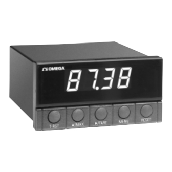
SECTION 2. ABOUT THE METER 2.1 FRONT OF THE METER Figure 2-1 shows each part of the front of the meter. Figure 2-1. Front Panel METER DISPLAY: Digital LED display: ¡. 9 . 9 . 9 . or 9. 9 . 9 . 9 . 4-digit 7–segment, 0.56"... - Page 10 METER BUTTONS T-RST button - Clears the tare value. £/MAX button - In the run mode, press the £/MAX button to show the maximum value if jumper S3 is installed: the meter momentarily shows “####”, then flashes the maximum value encountered since the last peak reset.
-
Page 11: Back Of The Meter
2.2 BACK OF THE METER Figure 2-2 shows the connectors on the back of the meter. Table 2-1 gives a brief description of each connector at the back of the meter. Refer to Figure 2-3 for dc-power connection information. Figure 2-2. Connectors for ac-Power (Top) and dc-Power (Bottom) Table 2-1. -
Page 12: Disassembly
2.2 BACK OF THE METER (Continued) Figure 2-3. dc-Power Connections 2.3 DISASSEMBLY You may need to open up the meter for one of the following reasons: To check or change the 115 or 230 Vac power jumpers. To install or remove calibration jumper on the main board. Disconnect the power supply before proceedings. -
Page 13: Getting Started
SECTION 3. GETTING STARTED CAUTION: The meter has no power-on switch, so it will be in operation as soon you apply power. If you power off/on the meter momentarily shows the following: “idP” for model type, “codE” , and “rxx” for the micro controller revision code. Keep track of revision code for future reference. -
Page 14: Mounting The Meter
3.1 CHANGING CONFIGURATION JUMPERS (Continued) Front of the meter Figure 3-1. S1 - S4 Jumpers 3.2 MOUNTING THE METER PANEL CUTOUT Figure 3-2. Meter - Exploded View... -
Page 15: Connecting Sensor Input
3.2 MOUNTING THE METER (Continued) PANEL THICKNESS 1. Cut a hole in your panel according to 6,4 (.25) MAX 0,8 (.03) MIN the dimensions specified in Figure 3-3. R(.06) 45,00 + 0,61/-0,00 2. Insert the meter into the hole. Be sure (1.772 + .024/–.000) 4 PLCS the front bezel is flush to the panel. -
Page 16: With External Excitation
3.3 CONNECTING SENSOR INPUT (Continued) 0 10Vdc SOURCE Figure 3-5. 2-Wire dc Voltage Input Connections with External Excitation EXTERNAL SUPPLY Figure 3-6. 4-20 mA Input Connections with External Excitation... -
Page 17: Ma Transmitter Hook-Up With Internal Excitation
3.3 CONNECTING SENSOR INPUT (Continued) HOLD Figure 3-7. 4-20 mA Transmitter Hook-Up with Internal Excitation Figure 3-8. dc Current Input Connections with Current Source... -
Page 18: Connecting Main Power
3.4 CONNECTING MAIN POWER Connect the ac main power connections as shown in Figure 3-9. WARNING: Do not connect ac power to your meter until you have complet- ed all input and output connections. Failure to do so may result in injury! 1 2 3 AC Power Earth... -
Page 19: Configuring The Meter
SECTION 4. CONFIGURING THE METER 4.1 SELECTING THE INPUT RANGE (INPT) Refer to Table B-2 for a summary list of menu configuration. To select your appropriate input range, follow these steps: 1. Press the MENU button. The meter flashes “InP”. 2. -
Page 20: Selecting A Decimal Point Position
4.2 SELECTING A DECIMAL POINT POSITION (DEC.P) Refer to Table B-2 for a summary list of menu configuration. To select a decimal point display position, follow these steps: 1. Press the MENU button until the meter shows “dEc.P”. 2. Press the ¢/TARE button. The meter shows one of the following: FFF.F FFFF. -
Page 21: Internal Scaling
4.3.1 Internal Scaling Use internal scaling if you do not have an actual input signal to the meter. With internal scaling the input values are assumed to be the low and high signal input based on the selection input (e.g. if you selected 4-20 mA input, the “rd1” input value will be 0400 for 4 mA and “rd2”... -
Page 22: Live Scaling
4.3.2 Live Scaling Use live scaling when a stable input source is available (e.g. 4-20 mA or voltage calibrator). Also use live scaling when the actual input from your sensor can be set to output values close to the low and high ends of your input. -
Page 23: Changing The Meter's Calibration
4.4 CHANGING THE METER S CALIBRATION CAUTION: It is not necessary to calibrate a brand new meter, it arrives completely calibrated. The following procedure modifies the calibration of the meter. This procedure should only be performed by qualified personnel with accurate test equipment. -
Page 24: Meter Calibration Table
4.4 CHANGING THE METER S CALIBRATION (Continued) 10. Press the MENU button for the meter to accept the new value. The meter then flashes “rd2” . 11. Apply the high input voltage or current for the selected input range (e.g. apply 9.900 V if you are calibrating 0-10 V range). -
Page 25: Checking And Changing Main Board Power Jumpers
APPENDIX A CHECKING AND CHANGING MAIN BOARD POWER JUMPERS IMPORTANT: If you want to change the Factory preset jumpers, do the following steps: Disconnect the power from the unit before proceeding. 1. Remove the main board from the case. Refer to Section 2.6. 2. -
Page 26: A-2 230 Vac Jumper Wiring
APPENDIX A - CHECKING AND CHANGING MAIN BOARD POWER JUMPERS (Continued) JUMPER 230Vac Figure A-2. 230 Vac Jumper Wiring... -
Page 27: Reference Tables
APPENDIX B REFERENCE TABLES Table B-1. Display Messages MESSAGE DESCRIPTION Peak value to follow Valley value to follow 123* Peak value reached overload 123* Valley value reached overload ER 1 Scaling format error PrSt Peak reset VrST Valley reset T-RST Tare reset. -
Page 28: Run Mode Displays
APPENDIX B - REFERENCE TABLES (Continued) Table B-3. Run Mode Displays Display RESET T-RST Jumpers ¢/TARE £/MAX PrST Press to Peak Reset activate installed VrST Press to Valley activate removed Reset Press to Peak Value installed activate* to follow Press to Valley removed activate*... -
Page 29: Specifications
APPENDIX C SPECIFICATIONS Analog Input Ranges: 4-20 mA, 0-5 Vdc, 1-5 Vdc, 0-10 Vdc Input Impedance: Voltage: 1.0 Meg Current: 100 Ω Isolation: Dielectric strength to 2500V transient per 3mm spacing base on EN61010 for 260Vrms or dc working voltage Accuracy: 0.05%R +/- LSB Tempco:... -
Page 30: Panel Cutout
APPENDIX C - SPECIFICATIONS (Continued) 48.00(1.890) 96.00 (3.780) 0.73 (18.67) 3.22 (81.7) 3.74 (95.0) SIDE VIEW TOP VIEW PANEL THICKNESS: 6,4 (.25) MAX 0,8 (.03) MIN 45,01 +0,61/-0,00 (.06) (1.772 +.024/-.000) 4 PLCS 92,00 +0,81/-0,00 (3.622 +.032/-.000) PANEL CUTOUT Figure C-1. Meter Dimensions... -
Page 31: Information
APPENDIX D - INFORMATION This product conforms to the EMC directive 89/336/EEC amended by 93/68/EEC, and with the European Low Voltage Directive 72/23/EEC. Electrical Safety EN61010-1:2001 Safety requirements for electrical equipment for measurement, control and laboratory. • Double Insulation: Primary to Secondaries •... - Page 32 INDEX Calibration and the S4 jumper 7 changing 17, 18 installing/removing calibration jumper 6 Configuration jumpers changing 7, 8 Configuration mode 3 escaping from 4 RESET button 4 ßMAX button 4 ∂TARE button 4 Connecting sensor input 9-11 Connector label 5 dc-power 6 2-wire voltage input connections 10 3-wire voltage input connection 9...
- Page 33 INDEX Live scaling 16 Main board power jumpers 23, 24 MENU button 4 Meter modes configuration mode 3 run mode 3 micro controller revision code accessing 7 Mounting the meter 9 RESET button 4 Resetting peak and valley registers 4, 20 Run mode 3 MENU button 4 RESET button 4...
- Page 34 Authorized Return (AR) number immediately upon phone or written request. Upon examination by OMEGA, if the unit is found to be defective, it will be repaired or replaced at no charge. OMEGA’s WARRANTY does not apply to defects resulting from any action of the purchaser, including but not limited to mishandling, improper interfacing, operation outside of design limits, improper repair, or unauthorized modification.
- Page 35 Where Do I Find Everything I Need for Process Measurement and Control? OMEGA…Of Course! Shop on line at omega.com TEMPERATURE Thermocouple, RTD & Thermistor Probes, Connectors, Panels & Assemblies Wire: Thermocouple, RTD & Thermistor Calibrators & Ice Point References Recorders, Controllers & Process Monitors...