Table of Contents
Advertisement
Quick Links
Advertisement
Table of Contents

Related Manuals for Furuno RD-20


Summary of Contents for Furuno RD-20
- Page 1 OPERATOR'S MANUAL REMOTE DISPLAY RD-20 Model www.furuno.com...
-
Page 3: Important Notices
How to discard a used battery Some FURUNO products have a battery(ies). To see if your product has a battery, see the chapter on Maintenance. Follow the instructions below if a battery is used. Tape the + and - terminals of bat- tery before disposal to prevent fire, heat generation caused by short circuit. -
Page 4: Safety Instructions
Failure to turn off the equipment can Connection of an incorrect power cause fire or electrical shock. supply can cause fire or equipment Contact a FURUNO agent for service. damage. The voltage rating of the equipment appears on the label Keep heater away from the above the power connector. -
Page 5: Table Of Contents
TABLE OF CONTENTS FOREWORD ........................iv SYSTEM CONFIGURATION ................... v OPERATION ......................1 1.1 Controls .........................1 1.2 How to Turn the Power On and Off ................3 1.3 How to Adjust Display Brilliance ..................3 1.4 How to Select a Screen ....................4 1.5 How to Select the Units of Measurement ..............8 1.6 How to Select the Display Mode..................8 1.7 How to Set the User Menu ..................10... -
Page 6: Foreword
FOREWORD A Word to the Owner of the RD-20 Remote Display Congratulations on your choice of the FURUNO RD-20 Remote Display. We are confident you will see why the FURUNO name has become synonymous with quality and reliability. Since 1948, FURUNO Electric Company has enjoyed an enviable reputation for innovative and dependable marine electronics equipment. -
Page 7: System Configuration
Remote display RD-20 FURUNO RD-20 DISP UNIT MODE BRILL FURUNO FURUNO 12-24 VDC DISP UNIT MODE BRILL DIMMER CONTROLLER REMOTE CONTROLLER RD-501 RD-502 NMEA0183 sensor signal Remote controller Dimmer controller RD-501 RD-502 Environmental category: Protected from weather: RD-20, RD-501, RD-502... - Page 8 REMOTE CONTROLLER RD-501 RD-502 FURUNO BRILL DIMMER CONTROLLER RD-502 Note: When turning off the power for a RD-20 in the daisy chain connection, the RD-20s which are connected after that RD-20 can receive neither the sensor signal nor the brilliance signal.
-
Page 9: Operation
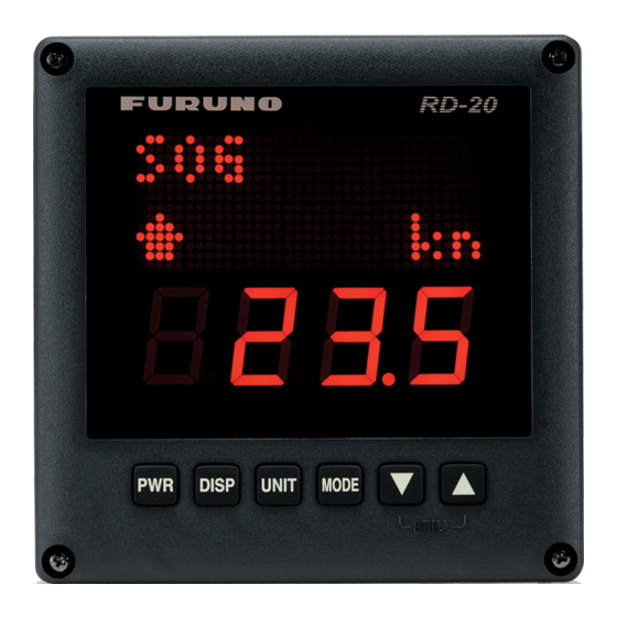
OPERATION Controls Remote display RD-20 RD - 20 DISP UNIT MODE Control Description Turn on/off the power. DISP Switch the screen. UNIT Select the units of measurement for the current screen. MODE Select the mode for the current screen. , ... - Page 10 1. OPERATION Remote controller RD-501 DISP UNIT MODE REMOTE CONTROLLER RD - 501 Control Description DISP Switch the screen. UNIT Select the units of measurement for the current screen. MODE Select the mode for the current screen. Dimmer controller RD-502 BRILL DIMMER CONTROLLER RD - 502...
-
Page 11: How To Turn The Power On And Off
To adjust the display brilliance, press , , or DAY/NT key. The setting range is 0 to 9. "0" is off and "9" is the brightest. Operation with main RD-20 The main RD-20 simultaneously controls the display brilliance of the main RD-20 and the sub RD- 20s. • Controls with key: Decrease the display brilliance. -
Page 12: How To Select A Screen
1. OPERATION How to Select a Screen Screen The screen for the RD-20 changes as follows with the DISP key. When you start the RD-20, the last-used screen appears. Availability of data depends on your system configuration. Display mode SOG AUTO... - Page 13 1. OPERATION (Continued from previous page) RUDDER Current rudder position (S: STBD (starboard), STBD deg Direction of ship’ s turn P : PORT, (STBD or : Starboard side, 9 .4 No indication: SINGLE) PORT or : Port side, No indication: When 0.0 or 180.0 deg) Rudder angle DISP key ORDER...
- Page 14 1. OPERATION List of terms The following table shows the terms used in the RD-20. Term Meaning Percent °C Degree(s) Celsius °F Degree(s) Fahrenheit 1AXIS 1-axis 7-SEG 7-Segment 38.4k 38.4Kbps 4.8k 4.8Kbps A, AUTO Automatic After Ahead ARROWS Arrows Astern...
- Page 15 1. OPERATION Term Meaning MAIN Main MENU Menu Miles per hour Meter/second No Good Nautical Mile Number Night OFFSET Offset ORDER Rudder Angle Order Output PITCH Propeller Pitch P, PORT Port/Port Side Power Relative: Relative or apparent wind. The wind direction relative to the ship’s bow and the wind speed relative to the moving vessel.
-
Page 16: How To Select The Units Of Measurement
1. OPERATION Term Meaning WIND Wind How to Select the Units of Measurement You can select the units of measurement for speed, distance, depth, wind speed and water tem- perature. 1. Press the DISP key to display the screen which you want to change the units of measurement. 2. - Page 17 1. OPERATION • Rate of turn: Turn on/off the broken line under the indication “ROT”. Display mode (ON: Broken line* scrolls across P deg/min *: The scrolling speed of the the screen (Starboard: from left broken line increases with 1 0 . 6 to right, Port: from right to left), rate of turn speed.
-
Page 18: How To Set The User Menu
WIND Display mode (T: Theoretical, 084.5 PORT/STBD/no indication: Relative) How to Set the User Menu The user menu lets you adjust the RD-20 to meet your needs. Menu Description Setting Default KEY LED BRILL Set the brilliance for key LED. - Page 19 1. OPERATION BRILL Set the brilliance for key LED using key. UNIT key MODE key Select an item to display among [ENGINE], [SHAFT], or [PITCH]. RPM SET RPM SET RPM SET ENGINE PITCH SHAFT UNIT key MODE key RPM SET Select the number of engine, shaft or propeller using...
-
Page 20: Maintenance, Troubleshooting
MAINTENANCE, TROUBLE- SHOOTING NOTICE Do not apply paint, anti-corrosive sealant or contact spray to coating or plastic parts of the equipment. Those items contain organic solvents that can damage coating and plastic parts, especially plastic connectors. Maintenance Check the following points regularly to maintain performance: •... -
Page 21: Life Of The Parts
The consumption current depends on the number of lighting LEDs and the LED brilliance. Error Screens When the NMEA sentences are not input or are timed out, the RD-20 displays the following error screens. DEPTH - - - - - - . -... - Page 22 Program version number Test results • Model name: The model name "RD-20" is displayed. • LED test (pattern 1 and 2): Check that all LED segments light. • ROM, RAM: The results of the ROM/RAM test are displayed as OK or NG (No Good). If any NG is displayed, contact your dealer for instruction.
-
Page 23: Simulation Mode
Simulation Mode The simulation mode, which shows internally generated navigation data, is provided to acquaint you with the features of the RD-20. "SIM" appears and flashes at the upper-right corner of the screen when the simulation mode is turned on. -
Page 24: Parts Location And Parts List
2. MAINTENANCE, TROUBLESHOOTING Parts Location and Parts List Parts Location RD-20 26P0009 Rear side 26P0009 26P0008 Cover opened RD-501/502 RD-501: 26P0012A RD-502: 26P0012B Cover opened... -
Page 25: Parts List
2. MAINTENANCE, TROUBLESHOOTING Parts List ELECTRICAL PARTS Model RD-20 Unit Remote display RD-20 PRINTED CIRCUIT BOARD Code No. 26P0008, PNL 26P0009, MAIN ELECTRICAL PARTS Model RD-501 Unit Remote controller RD-501 PRINTED CIRCUIT BOARD Code No. 26P0012A, RMT ELECTRICAL PARTS Model... -
Page 26: Installation
INSTALLATION Equipment List Standard supply Name Type Code No. Remarks Remote Display RD-20 Installation Materials CP26-01001* 001-076-460-00 Accessories FP26-00301* 001-076-470-00 Spare Parts SP26-00101* 001-076-450-00 Optional supply Name Type Code No. Remarks Remote Controller RD-501 Including CP26-01101* Dimmer Controller RD-502 Including CP26-01201*... -
Page 27: Flush Mounting
3. INSTALLATION Flush mounting 1. Make a cutout in the mounting location (132 mm (width) x 120 mm (height)). 2. Make four pilot holes for self-tapping screws (diameter: 3 mm) in the location indicated in the illustration below. 3. Insert the sponge to the remote display from the rear side. 4. -
Page 28: Installation Of Remote Controller And Dimmer Controller
3. INSTALLATION How to set the cosmetic cap Set a cosmetic cap to each fixing screw on the front panel as shown below. Set cosmetic cap to hole so cap is flush with panel. Installation of Remote Controller and Dimmer Controller The optional remote controller RD-501 and dimmer controller RD-502 can be flush mounted in a panel. -
Page 29: Wiring
3. INSTALLATION Wiring Interconnection Refer to the interconnection diagram (page S-1) to connect cables. Single remote display Remote display RD-20 1 2 11 10 9 8 7 6 5 4 3 2 1 φ4 DPYC-1.5 12-24 VDC TTYCS-1 (max. 100 m) - Page 30 RD-501 RD-502: b RD-502: a RD-502: a RD-502: a FURUNO FURUNO Brilliance for RD-20 D Brilliance for RD-20 A, B and C is and E is controlled by controlled by RD-502 a. BRILL BRILL DIMMER CONTROLLER DIMMER CONTROLLER RD-502 b.
- Page 31 RD2B RD-501 RD-502 Note: When you turn off the power for a RD-20 in the daisy chain connection, the RD-20s which are connected after that RD-20 can receive neither the sensor signal nor the brilliance signal. Connection of each unit Process each cable referring to the illustrations below and on the next page.
- Page 32 3. INSTALLATION Fabrication of cable TTYCS-4 between RD-20 and RD-501/502 RD-20 RD-501/502 Arbitrary Arbitrary length length Armor Armor Sheath Sheath Shield Shield Vinyl tape Vinyl tape Fabrication of cable TTYCS-4 between RD-501 and RD-502 RD-501 RD-502 Arbitrary Arbitrary length length...
- Page 33 3. INSTALLATION How to connect wires to WAGO connector Press downward. Terminal opener Wire WAGO connector Twist Procedure 1. Twist the cores. 2. Press the terminal opener downward. 3. Insert the wire to hole. 4. Remove the terminal opener. 5. Pull the wire to confirm that it is secure. Attach the WAGO connectors (with cables).
-
Page 34: Adjustments
3. INSTALLATION Adjustments After wiring each unit, initialize each remote display as follows: 1. While you hold down the MODE key, press the PWR key to turn on the power. SYS MENU MODE Note: If you press the MODE key with this screen shown, the equipment restarts. 2. - Page 35 3. INSTALLATION MODE key + PWR key MODE key SYS MENU SYS MENU Select [YES] to start The equipment MODE YES MODE the system menu. restarts. UNIT key MODE key Default SPEED SPEED Set the speed ([1 AXIS] or [VECTOR]). 1 AXIS VECTOR MODE key...
- Page 36 • [YES]: Clear the settings. Select [YES] and press the MODE key. The equipment restarts with the default settings. When clearing the settings for RD-20, the following items are restored to default. • Settings for the data display (screen mode), display mode, unit of measurement, direction of the ship, display brilliance •...
-
Page 37: Jis Cable Guide
DPYCYS - 1.5 MPYC - 5 Designation type Core Area (mm ) Designation type # of cores TTYCS-4 The following reference table lists gives the measurements of JIS cables commonly used with Furuno products: Core Cable Core Cable Diameter Diameter... -
Page 38: Specifications
5 VDC output (for remote/dimmer controller) Sensor Input: 1 port, NMEA0183 Ver1.5/2.0/3.0/4.0/4.1 Daisy chain (for RD-20) Output: 1 port, 38,400 bps Data sentences DBK, DBS, DBT, DPT, HDG, HDT, HDM, HTC, HTD, MTW, MWV, RPM, RMC, ROT, RSA, THS, VBW, VHW, VLW, VTG, VWT, VWR... -
Page 46: Interconnection Diagram
1) NMEAデータを共有する場合 TO USE NMEA DATA JOINTLY リモートディスプレイ TTYCS-4 Vout TD2A REMOTE DISPLAY リモート操作部 TD2B RD-20 REMOTE RD2A CONTROLLER RD2B 4 GND RD-501 TD2A 5 NC TD2B RD2A RD1A RD2B RD1B Vout 9 GND DC_H DC_C IV-1.25sq. IV-1.25sq. TD2A 調光器... -
Page 47: Ec Declaration Of Conformity
(title and/or number and date of issue of the standard(s) or other normative document(s)) For assessment, see • Test Report FLI 12-09-053, August 25, 2009 prepared by Furuno Labotech International Co., Ltd. This declaration is issued according to the Directive 2014/30/EU of the European Parliament and of the Council of 26 February 2014 on the harmonisation of the laws of the Member States relating to electromagnetic compatibility. - Page 48 ・FURUNO Authorized Distributor/Dealer 9-52 Ashihara-cho, Nishinomiya, 662-8580, JAPAN A : OCT 2009 Printed in Japan All rights reserved. D : APR . 03, 2017 Pub. No. OME-44540-D ( AKMU ) RD-20 0 0 0 1 7 2 0 1 2 1 3...