Fluke DTX-MFM2 User Manual
Fiber modules
Hide thumbs
Also See for DTX-MFM2:
- User manual (74 pages) ,
- Technical reference handbook (320 pages) ,
- User manual (62 pages)

Related Manuals for Fluke DTX-MFM2


Summary of Contents for Fluke DTX-MFM2
-
Page 1: Users Manual
DTX-MFM2/GFM2/SFM2 Fiber Modules Users Manual PN 2142235 April 2004, Rev. 3 5/07 © 2004, 2006, 2007 Fluke Corporation. All rights reserved. Printed in USA. All product names are trademarks of their respective companies. - Page 2 90 days, unless otherwise stated. Ni-Cad, Ni-MH and Li-Ion batteries, cables or other peripherals are all considered parts or accessories. The warranty extends only to the original buyer or end user customer of a Fluke Networks authorized reseller, and does not apply to any prod- uct which, in Fluke Networks’...
-
Page 3: Table Of Contents
Contacting Fluke Networks ..................2 Accessing the Technical Reference Handbook ............2 Additional Resources for Cable Testing Information..........2 Unpacking ........................3 DTX-MFM2 Multimode Fiber Modules..............3 DTX-GFM2 Multimode Fiber Modules ..............3 DTX-SFM2 Singlemode Fiber Modules ..............3 Safety Information......................4 Getting Acquainted ...................... - Page 4 DTX-MFM2/GFM2/SFM2 Fiber Modules Users Manual Selecting Reference Test Cords ................12 Testing Your Reference Test Cords ................. 12 Using Mandrels for Testing Multimode Fiber ............12 Fiber Test Settings ......................15 About Method B Connections ..................20 Certifying Fiber Cabling ....................21 Autotest in Smart Remote Mode ................
- Page 5 List of Figures Figure Title Page Installing and Removing Fiber Modules ................6 Fiber Module Features ......................7 SC, ST, LC, and FC Connector Adapters ................8 Installing the Connector Adapter ..................9 Wrapping a Reference Test Cord Around a Mandrel............14 Example of How to Determine the Number of Adapters Setting ........
- Page 6 DTX-MFM2/GFM2/SFM2 Fiber Modules Users Manual Equipment for Monitoring Optical Power ................. 40 Connections for Monitoring Optical Power ............... 42 B-1. Modified Method B: Smart Remote Mode Reference Connections........B-2 B-2. Modified Method B: Smart Remote Mode Test Connections..........B-3...
-
Page 7: Overview Of Features
1310 nm and 1550 nm. The troubleshooting tips, and other support services. To DTX-GFM2 features a VCSEL for testing multimode register, fill out the online registration form on the Fluke cabling at 850 nm and 1310 nm for Gigabit Ethernet Networks website at www.flukenetworks.com/registration. -
Page 8: Contacting Fluke Networks
Handbook Note The DTX Series CableAnalyzer Technical Reference If you contact Fluke Networks about your tester, Handbook provides additional information on the tester have the tester's software and hardware version and the fiber modules. The handbook is available on the numbers available if possible. -
Page 9: Unpacking
Two 9/125 m singlemode reference test cords, 2 m, purchase immediately. SC/SC DTX-MFM2 Multimode Fiber Modules DTX-MFM2/GFM2/SFM2 Fiber Modules Users Manual Two DTX-MFM2 Fiber Modules for testing at 850 nm DTX CableAnalyzer Product CD and 1300 nm LinkWare Software CD Two 62.5/125 m multimode reference test cords,... -
Page 10: Safety Information
DTX-MFM2/GFM2/SFM2 Fiber Modules Users Manual Never start a test or activate the OUTPUT port or Safety Information VFL port without first connecting a fiber to the Warning port you will use. Never look directly into the visual fault locator To avoid possible fire, electric shock, or personal injury read the safety information given in the output. - Page 11 Do not overtighten the adapter or use tools to Leave the module bay covers in place when the tighten the adapter. fiber modules are not installed. Use a Fluke Networks FiberInspector Video Turn off the tester before attaching or removing Microscope to periodically inspect the fiber modules.
-
Page 12: Getting Acquainted
DTX-MFM2/GFM2/SFM2 Fiber Modules Users Manual Getting Acquainted The following sections introduce the fiber modules’ features. Installing and Removing Fiber Modules Figure 1 shows how to install and remove the fiber modules. Caution Leave the module bay covers in place when the fiber modules are not installed. -
Page 13: Physical Features
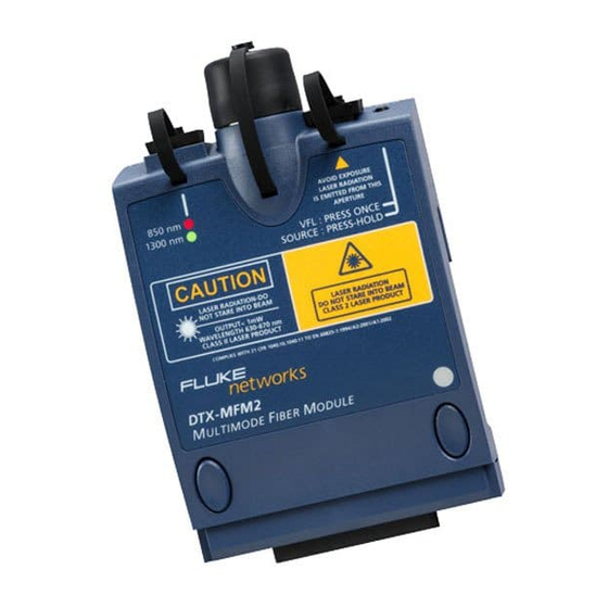
Getting Acquainted Physical Features Button for activating the visual fault locator (B) and output port (D). See “Using the Visual Fault Locator” on page 37 and “Autotest in Far End Source Mode” on page 32. Universal fiber connector (with dust cap) for the visual fault locator output. The connector accepts 2.5 mm ferrules. -
Page 14: Installing The Connector Adapter
Additional adapter styles may be available. Check the Holding the adapter so it does not turn in the nut, Fluke Networks web site for updates. align the adapter's key with the module connector's slot and slide the adapter onto the connector. -
Page 15: Installing The Connector Adapter
Installing the Connector Adapter amd99f.eps Figure 4. Installing the Connector Adapter... -
Page 16: Essentials For Reliable Fiber Test Results
Results Inspect connectors with a fiber microscope, such as To get reliable fiber test results, you must follow proper the Fluke Networks FiberInspector Video Microscope cleaning and referencing procedures and, in some cases, before making connections. use mandrels during testing. -
Page 17: About Setting The Reference
Essentials for Reliable Fiber Test Results Connector Adapters and Fiber Adapters You should set the reference at these times: Periodically clean connector adapters and fiber adapters At the beginning of each day using the remote end with a swab and alcohol. Dry with a dry swab before use. setup (Figures 9 through 15) you will use that day. -
Page 18: Selecting Reference Test Cords
You should use mandrels when testing multimode fiber connections. with the DTX-MFM2 fiber modules. Mandrels can See the sections on Smart Remote, Loopback, and Far improve measurement repeatability and consistency. End Source modes for details on setting the reference for They also allow the use of LED light sources to certify 50 each mode. - Page 19 Essentials for Reliable Fiber Test Results The gray mandrels included with the DTX-MFM2 are Figure 5 shows how to wrap the fiber around a mandrel. compliant with TIA/EIA-568-B for 62.5 m fiber with a Place mandrels on the tester’s output fibers, as shown in 3 mm jacket.
-
Page 20: Wrapping A Reference Test Cord Around A Mandrel
DTX-MFM2/GFM2/SFM2 Fiber Modules Users Manual Place top wrap in groove under retainer Wrap 5 times in grooves Right: no bends Wrong: at retainer bends at retainer amd67f.eps Figure 5. Wrapping a Reference Test Cord Around a Mandrel... -
Page 21: Fiber Test Settings
Fiber Test Settings To access the fiber test settings turn the rotary switch to Fiber Test Settings SETUP; then select Fiber Loss. Use to see different Table 2 describes the test settings that apply to fiber tabs. cabling. Table 2. Fiber Test Settings Setting Description SETUP >... - Page 22 DTX-MFM2/GFM2/SFM2 Fiber Modules Users Manual Table 2. Fiber Test Settings (cont.) Setting Description SETUP > Fiber Loss > When enabled in Smart Remote or Loopback mode, the tester prompts you to swap the test Bi-Directional connections halfway through the test. The tester can then make bi-directional measurements for each fiber at each wavelength (850 nm/1300 nm, 850 nm/1310 nm, or 1310 nm/1550 nm).
-
Page 23: Example Of How To Determine The Number Of Adapters Setting
Fiber Test Settings amd65f.eps Figure 6. Example of How to Determine the Number of Adapters Setting (singlemode example; mandrels not used) - Page 24 DTX-MFM2/GFM2/SFM2 Fiber Modules Users Manual Table 2. Fiber Test Settings (cont.) Setting Description SETUP > Fiber Loss results include connections added after referencing. The reference and test connections determine Loss > which connections are included in results. The Test Method refers to the number of end connections Test Method >...
- Page 25 Fiber Test Settings Table 2. Fiber Test Settings (cont.) Setting Description SETUP > Fiber Loss > The tester uses the index of refraction (n) defined in the currently selected fiber type (Default) or Index of Ref. Source (n) a value you define (User Defined). The default value defined by the selected fiber type >...
-
Page 26: About Method B Connections
To ensure accurate results, the DTX Series CableAnalyzer Technical Reference Handbook connection to the fiber module's output port must not be or visit the Fluke Networks Knowledge Base for disconnected after the reference is set. Using connector suggestions. -
Page 27: Certifying Fiber Cabling
Memory card (optional) Two mandrels. Recommended when testing multimode fiber with DTX-MFM2 modules. See page 12. Two ac adapters with line cords (optional) Fiber cleaning supplies Figure 7. Equipment for Testing in Smart Remote Mode (Method B) - Page 28 DTX-MFM2/GFM2/SFM2 Fiber Modules Users Manual Autotest in Smart Remote Mode Turn on the tester and smart remote and let them sit for Connector Type: Select the connector type used in 5 minutes. Allow additional time if the modules have the cabling to be tested. Select General if the exact been stored above or below ambient temperature.
-
Page 29: Smart Remote Mode Reference Connections (Method B)
Certifying Fiber Cabling amd145f.eps Figure 8. Smart Remote Mode Reference Connections (Method B) - Page 30 DTX-MFM2/GFM2/SFM2 Fiber Modules Users Manual Autotest in Smart Remote Mode (cont.) Verify that the tester at the other end is on. (The Caution tester cannot activate a sleeping or powered-down If you disconnected the reference test cords from tester at the far end through the fiber modules.) the tester’s or smart remote’s output, you must set...
-
Page 31: Smart Remote Mode Test Connections (Method B)
Certifying Fiber Cabling amd146f.eps Figure 9. Smart Remote Mode Test Connections (Method B) -
Page 32: Autotest In Loopback Mode
DTX-MFM2/GFM2/SFM2 Fiber Modules Users Manual In this mode, the tester measures loss, length, and Autotest in Loopback Mode propagation delay at two wavelengths in one or both Use Loopback mode to test spools of cable, segments of directions. uninstalled cable, and reference test cords. -
Page 33: Equipment For Testing In Loopback Mode (Method B)
Two adapters of the appropriate type installed (match connector adapter to the connectors in Mandrel. Recommended when testing multimode fiber the link) with a DTX-MFM2 module. See page 12. Memory card (optional) Fiber cleaning supplies AC adapter with line cord (optional) Reference test cord. - Page 34 DTX-MFM2/GFM2/SFM2 Fiber Modules Users Manual Autotest in Loopback Mode Turn on the tester and smart remote and let them sit for Connector Type: Select the connector type used in 5 minutes. Allow additional time if the modules have the cabling to be tested. Select General if the exact been stored above or below ambient temperature.
-
Page 35: Loopback Mode Reference Connections (Method B)
Certifying Fiber Cabling amd147f.eps Figure 11. Loopback Mode Reference Connections (Method B) - Page 36 DTX-MFM2/GFM2/SFM2 Fiber Modules Users Manual Autotest in Loopback Mode (cont.) Press Caution If you disconnected the reference test cord from If bi-directional testing is enabled, the tester prompts the tester’s output port, you must set the reference you to switch the fibers halfway through the test.
-
Page 37: Loopback Mode Test Connections (Method B)
Certifying Fiber Cabling amd148f.eps Figure 12. Loopback Mode Test Connections (Method B) -
Page 38: Autotest In Far End Source Mode
Mandrel. Recommended when testing multimode fiber Memory card (optional) with a DTX-MFM2 module. See page 12. Two AC adapters with line cords (optional) Fiber cleaning supplies Reference test cord. Match the fiber to be tested. SC connector at one end. - Page 39 Certifying Fiber Cabling Autotest in Far End Source Mode Turn on the tester and smart remote and let them sit for Bi-directional: Does not apply to Far End Source 5 minutes. Allow additional time if the modules have mode. been stored above or below ambient temperature. For Number of Adapters and Number of Splices: Does other sources, warm up according to the manufacturer’s not apply to Far End Source mode.
- Page 40 If you disconnect the reference test cord from the 850 nm (DTX-MFM2/GFM2) or 1310 nm (DTX-SFM2). source’s output port, you must set the reference Press again to switch to 1300 nm (DTX-MFM2), 1310 nm again to ensure valid measurements. (DTX-GFM2), or 1550 nm (DTX-SFM2).
-
Page 41: Far End Source Mode Reference Connections (Method B)
Certifying Fiber Cabling amd149f.eps Figure 14. Far End Source Mode Reference Connections (Method B) -
Page 42: Far End Source Mode Test Connections (Method B)
DTX-MFM2/GFM2/SFM2 Fiber Modules Users Manual amd150f.eps Figure 15. Far End Source Mode Test Connections (Method B) -
Page 43: Using The Visual Fault Locator
Using the Visual Fault Locator Using the Visual Fault Locator The fiber module includes a visual fault locator that helps you quickly check fiber continuity, trace fibers, and locate faults along fibers and in connectors. The visual fault locator port accepts connectors with 2.5 mm ferrules (SC, ST, or FC). - Page 44 DTX-MFM2/GFM2/SFM2 Fiber Modules Users Manual Using the Visual Fault Locator Clean the connectors on the reference test cord, if Look for the red light to locate fibers or faults (Figure 17): used, and the fiber to be tested. To check continuity or trace fiber connections, look Connect the fiber directly to the tester’s VFL port or...
-
Page 45: Using The Visual Fault Locator
Using the Visual Fault Locator amd23f.eps Figure 17. Using the Visual Fault Locator... -
Page 46: Monitoring Optical Power
SINGLE TEST mode: Measures power in the current remote end configuration (Smart Remote, Loopback, or Far End Source mode). Takes one power measurement at 850 nm and 1300 nm (DTX-MFM2), 850 nm and 1310 nm (DTX-GFM2), or 1310 nm and amd57f.eps 1550 nm (DTX-SFM2). - Page 47 Monitoring Optical Power Monitoring Optical Power Clean the tester’s input port and the reference test cord Select Power Meter. You do not need to select a fiber and source connectors. type or test limit. Select the correct wavelength; then press Use the reference test cord to connect the source to the tester’s input port, as shown in Figure 19.
-
Page 48: Connections For Monitoring Optical Power
DTX-MFM2/GFM2/SFM2 Fiber Modules Users Manual amd58f.eps Figure 19. Connections for Monitoring Optical Power... -
Page 49: Options And Accessories
Options and Accessories and accessories visit the Fluke Networks website at Options and Accessories www.flukenetworks.com. Table 3 shows options and accessories available for the To order options or accessories, contact Fluke Networks DTX Series CableAnalyzers. For a complete list of options as described on page 2. - Page 50 DTX-MFM2/GFM2/SFM2 Fiber Modules Users Manual Table 3. Options and Accessories (cont.) Option or Accessory Fluke Networks Model Number SC/SC to SC/SC duplex 62.5 m/125 m reference test cord, 2 m (2) NFK1-DPLX-SC SC/LC to LC/LC duplex 62.5 m/125 m reference test cord, 2 m (2) NFK1-DPLX-LC SC/ST to ST/ST duplex 62.5 m/125 m reference test cord, 2 m (2)
- Page 51 Options and Accessories Table 3. Options and Accessories (cont.) Option or Accessory Fluke Networks Model Number DTX-FTK Fiber Test Kit DTX-FTK ™ Fiber optic meter module and 850 nm/1300 nm SimpliFiber source. Measures power and loss at 850 nm/1300 nm (1310 nm/1550 nm with optional source).
- Page 52 DTX-MFM2/GFM2/SFM2 Fiber Modules Users Manual Table 3. Options and Accessories (cont.) Option or Accessory Fluke Networks Model Number ST/ST singlemode fiber optic adapter NF300SM SC/SC singlemode fiber optic adapter NF310SM ST/FC simplex 62.5 µm 1m patch cord FOC-ST/FC ST/ST simplex 62.5 µm 1m patch cord FOC-ST/ST ST/SC simplex 62.5 µm 1m patch cord...
-
Page 53: Maintenance
Series CableAnalyzer Users Manual. You can use a DTX Series smart remote with a DTX-MFM2 or DTX-SFM2 fiber module as the remote for Clean the optical connectors as described on page 10. a Fluke Networks OptiFiber Certifying OTDR. The DTX... -
Page 54: Certification, Compliance, And Regulatory Information
DTX-MFM2/GFM2/SFM2 Fiber Modules Users Manual Certification, Compliance, and Regulatory Information Conforms to relevant Australian standards N10140 Conforms to relevant European Union directives. Listed by the Canadian Standards Association. Laser safety OUTPUT port: Class 1 VFL port: Class 2 Complies with EN60825-1 and... -
Page 55: Appendix A: Test Method Reference Tables
Appendix A: Test Method Reference Tables Industry standards use different names for equivalent test methods. Table A-1 shows the names used in this manual and by four common industry standards for the three fiber test methods Table A-1. Test Method Names Link End Connections This TIA/EIA-526-14A... - Page 56 DTX-MFM2/GFM2/SFM2 Fiber Modules Users Manual Table A-2 shows the test methods required by standards. Table A-2. Test Methods Required by Standards Standard or Standard or Application Test Method Application Test Method TIA-568-B 10GBASE-S ISO 11801 10GBASE-L EN50173 10GBASE-LX 10BASE-FB 10GBASE-E...
-
Page 57: Appendix B: Modified Method B
Appendix of the the fiber under test. This method lets you connect to the DTX Series CableAnalyzer Technical Reference Handbook fiber without disturbing the fiber modules' output or visit the Fluke Networks Knowledge Base for connections after setting the reference. suggestions. -
Page 58: B-1. Modified Method B: Smart Remote Mode Reference Connections
DTX-MFM2/GFM2/SFM2 Fiber Modules Users Manual Reference test cord: MT-RJ to MT-RJ adapter Mandrel* SC to MT-RJ (pinned) Reference test cord: SC to MT-RJ (no pins) Mandrel* Tester Smart remote Caution Do not disconnect the outputs ( Mandrels used only for... -
Page 59: B-2. Modified Method B: Smart Remote Mode Test Connections
Do not disconnect ENTER SAVE the outputs ( AUTO TEST SINGLE SETUP TEST SPECIAL MONITOR FUNCTIONS Mandrels used only for multimode fiber tested with TALK TALK the DTX-MFM2 modules amd48f.eps Figure B-2. Modified Method B: Smart Remote Mode Test Connections... - Page 60 DTX-MFM2/GFM2/SFM2 Fiber Modules Users Manual...
-
Page 61: Index
(Method B), 36 cautions, 4 Loopback mode FC connector adapter, 8 cleaning connectors and adapters, 10 Autotest, 28 Fiber Type, 15 connections. See Smart Remote, equipment, 27 Fluke Networks Loopback, or Far End Source mode reference connections, 29... - Page 62 DTX-MFM2/GFM2/SFM2 Fiber Modules Users Manual results, 30 power meter, 40 test connections, 25 test connections (Method B), 31 ST connector adapter, 8 loss is negative, 11 —R— —T— reference —M— alternate connections, 18 Test Limit, 15 Method A, B, C, 18...