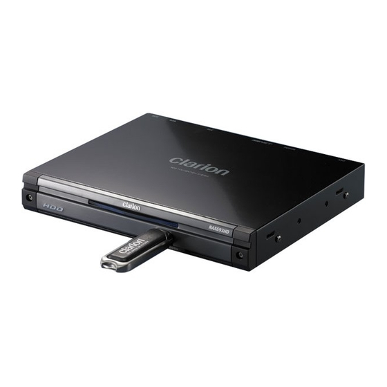
Clarion NAX963HD Service Manual
Hdd navigation system
Hide thumbs
Also See for NAX963HD:
- Installation and wire connection manual (82 pages) ,
- Owner's manual (607 pages)
Table of Contents
Advertisement
Quick Links
Service information
Control no.: 06SI010-R
1) Model outline:
NAX963HD
2) Description:
The navigation shows "ACCESS ERROR" on the display, as shown below.
3) Solution
Reset the NAX963HD navigation unit to the factory setting by following
the below mentioned procedure:
1) Press "Menu" on the main unit.
2) Select "Settings" on the touch screen
3) Press "Next"
4) Select " Service option"
5) Select "Reset to Factory Settings"
6) Press "OK", when asked for.
CLARION Europa GmbH, Hessenring 19-21, 64546 Morfelden-Walldorf, ++49 6105 / 977-0 Fx / 977-100
06SI010-R
HDD access error message
10.11.06
Page 1 of 2
Advertisement
Table of Contents

Related Manuals for Clarion NAX963HD


Summary of Contents for Clarion NAX963HD
- Page 1 3) Press “Next” 4) Select “ Service option” 5) Select “Reset to Factory Settings” 6) Press “OK”, when asked for. CLARION Europa GmbH, Hessenring 19-21, 64546 Morfelden-Walldorf, ++49 6105 / 977-0 Fx / 977-100 06SI010-R 10.11.06 Page 1 of 2...
- Page 2 After the installation of the factory settings, the NAX963HD will start up automatically. It may happen that the NAX963HD show this error message again. In this case, switch off the unit and restart it manually. Now the error message shall not be shown again.
-
Page 3: Specifications
Clarion Co., Ltd. Published by Service Dept. 50 Kamitoda, Toda-shi, Saitama 335-8511 Japan 298-6375-00 AUG.2006 Service Dept.: 5-66 Azuma , Kitamoto-shi, Saitama 364-0007 Japan Printed in Japan Tel: +81-48-541-2335 / 2432 FAX: +81-48-541-2703 Service Manual HDD Navigation System Model (QY-5000E-A) - Page 4 Also take care not to apply the tip with force. 9. Turn the unit OFF during disassembly and parts replacement. Recheck all work before you apply power to the unit. NAX963HD - 2 -...
-
Page 5: Troubleshooting
Please wait until vehicle is extremely low temperature becomes normal again. ACCESS ERROR The HDD cannot be accessed. Malfunction occured in the HDD. The sectors or clusters of the Please consult your nearest dealer. HDD may be damaged. NAX963HD - 3 -... -
Page 6: Block Diagram
BLOCK DIAGRAM Video/Audio/Control block NAX963HD - 4 -... -
Page 7: Reset Block
Reset block NAX963HD - 5 -... -
Page 8: Power Detect Block
Power detect block NAX963HD - 6 -... -
Page 9: Power Circuit Block
Power circuit block NAX963HD - 7 -... -
Page 10: Wire Connection
Reverse gear signal (Purple/white) Ground (Black) Power supply lead Microphone for voice control (854-6451-50) (081-0034-00) GPS antenna RDS-TMC antenna (096-0147-00) (ZCP-412-310) NAX963HD CeNET cable RGB cable (855-3421-90) (855-2433-01) VRX868RVD Connectors Front view (inside of Escutcheon) Rear view Power supply connector... - Page 11 :I/O: Bootstrap capacitor connection for CH1 high-side gate drive. Terminal Description 1: I SENSE : The current sense input pin. This pin should be connected to Drain node of the external PFET. 2: GND : Signal ground. NAX963HD - 9 -...
- Page 12 : 2.5V power supply for AUX. CLK 2 CLK 4 8: A4 : Address input. 9: A3 : Address input. CLK 1 pin 10: GND : Ground. CLK 3 pin 11: A2 : Address input. pin 12: A1 : Address input. NAX963HD - 10 -...
- Page 13 77: TCK : For JTAG. pin 15: PC 3 OUT : Phase Comparator 3 Output pin 78: TMS : For JTAG. pin 16: VCC : Positive Supply Voltage pin 79: GYRO_DATA : Data input from GYRO-ADC. NAX963HD - 11 -...
- Page 14 IN 2 6 Truth Table IN 2 IN 1 IN 0 051-7520-08 SN74LVC1G04DCKR Single Inverter 051-7537-90 SN74LVC1G14DCKR Single Schmitt-Trigger Inverter Gate 051-7522-08 SN74LVC1G32DCKR Single 2-inputs OR Gate N.C. 051-7539-90 SN74LVC3G34DCTR Triple Buffers 051-7524-08 SN74LVC1G08DCK Single 2-inputs AND GATE NAX963HD - 12 -...
- Page 15 : IN : Clock enable signal input. pin 45: CK : IN : Master clock input. pin 46: /CK : IN : Master clock input. pin 47: Upper DM : IN : When this pin is High, the data input are NAX963HD - 13 -...
- Page 16 27: NU : Not in use. pin 85: TX4/HSPI0_TX : Serial data output pin 28: NU : Not in use. pin 86: TX7/HSPI1_TX : Serial data output to sub-microcomputer pin 29: VSSDLL : DLL ground NAX963HD - 14 -...
- Page 17 VDD : Core 1.25V power supply pin204: NU : Not in use. pin145: VSSQ25 : DDR ground pin205: NU : Not in use. pin146: VSS : Core power ground pin206: DSDM[2] : DDR-SDRAM data select output NAX963HD - 15 -...
- Page 18 : IDE data input/output pin323: IDEA[2] : IDE address output pin264: IDERST# : IDE reset output pin324: IDEA[0] : IDE address output pin265: DIRECTION : IDE bus buffer direction control output pin325: IDEA[1] : IDE address output NAX963HD - 16 -...
- Page 19 : I/O 3.3V power supply pin440: NU : Not in use. pin382: VSS : Core power ground pin441: A[2] : EXBUS Address output. pin383: VDD : Core 1.25V power supply pin442: A[6] : EXBUS Address output. NAX963HD - 17 -...
- Page 20 : - : Not in use. pin 41: NU : - : Not in use. pin501: NU : Not in use. pin 42: NU : - : Not in use. pin502: NU : Not in use. NAX963HD - 18 -...
- Page 21 : IN : RSTIN# : Reset. pin 15: NU : - : Not in use. 2 : H1 : IN : CE# : Chip enable. pin 16: NAVI MONI : IN : L = SH7770 is stop. NAX963HD - 19 -...
- Page 22 76: NU : - : Not in use. pin 77: NU : - : Not in use. pin 78: NU : - : Not in use. pin 79: NU : - : Not in use. NAX963HD - 20 -...
-
Page 23: Exploded View Parts List
714-3006-8B MACHINE SCREW(M3x6) 347-7964-00 INSULATOR 060-8059-00 GPS-RECEIVER 780-2604-03 SCREW(M2.6x4) 331-4190-00 J-PLATE 331-4191-00 HDD-PLATE ----------- RDS-TMC PWB 286-6796-00 SETPLATE 331-4187-00 ANTENA-HOLDER ----------- HARD DISC DRIVE(30GB) 331-4317-00 RDS-SHIELD 331-3660-01 HDD BRKT 714-2605-8B MACHINE SCREW(M2.6x5) 716-0878-50 SCREW(M2.6x5) 880-1431D RDS-TMC-TUNER NAX963HD - 21 -... -
Page 24: Electrical Parts List
166-1011-50 100pF CH C428 166-1011-50 100pF CH C161 046-1042-78 0.1uF C239 042-0423-20 10V 10uF C429 168-1022-55 1000pF K C162 046-1042-78 0.1uF C240 042-0423-20 10V 10uF C502 046-1042-78 0.1uF C163 046-1042-78 0.1uF C241 046-1042-78 0.1uF C503 046-1042-78 0.1uF NAX963HD - 22 -... - Page 25 168-2212-55 220pF K C1048 042-1726-90 6.3V 100uF C611 168-1022-55 1000pF K C900 168-1032-55 0.01uF K C1049 042-1726-90 6.3V 100uF C700 168-1045-56 0.1uF Z C901 046-1042-78 0.1uF C1050 043-0548-50 2.2uF C701 168-4745-79 0.47uF Z C902 168-3332-78 0.033uF K NAX963HD - 23 -...
- Page 26 CCT303 050-0140-66 1/32W 47 ohm x4J DCKR IC1002 051-3298-90 TDA3664/N1 CCT304 050-0140-66 1/32W 47 ohm x4J IC200 051-9333-30 MT46V16M16P-6T IC1003 051-3377-90 LM3485MM CCT305 050-0140-66 1/32W 47 ohm x4J IC1004 051-3342-90 BA05CC0WFP- CCT306 050-0140-66 1/32W 47 ohm x4J IC201 051-9333-30 MT46V16M16P-6T 004EL NAX963HD - 24 -...
- Page 27 119-2211-15 1/10W 220 ohm R317 119-4701-15 1/10W 47 ohm L1007 010-3104-54 600 ohm/100MHz R128 032-0140-83 1/10W 150 ohm F R318 119-4701-15 1/10W 47 ohm L1008 010-3104-53 220 ohm/100MHz R129 032-0140-83 1/10W 150 ohm F R319 119-4701-15 1/10W 47 ohm NAX963HD - 25 -...
- Page 28 R1108 119-4721-15 1/10W 4.7k ohm R724 119-0000-05 1/10W 0 ohm JW R942 119-1011-15 1/10W 100 ohm R1109 119-1011-15 1/10W 100 ohm R727 119-1041-15 1/10W 100k ohm R943 119-1011-15 1/10W 100 ohm R1110 116-3321-15 1/4W 3.3k ohm NAX963HD - 26 -...
- Page 29 C2302 166-2201-50 22pF CH Q2101 125-2027-91 DTC114EUA R2303 119-3941-15 1/10W 390k ohm C2303 168-3932-78 0.039uF K Q2102 125-9015-94 RN4904 R2304 119-1021-15 1/10W 1k ohm C2304 166-1221-50 1200pF CH Q2201 190-1298-00 2SA1298 R2305 119-2721-15 1/10W 2.7k ohm NAX963HD - 27 -...
- Page 30 119-3921-15 1/10W 3.9k ohm R2316 119-1511-15 1/10W 150 ohm 039-2936-00 PWB(WITHOUT R2310 119-3331-15 1/10W 33k ohm R2317 119-3321-15 1/10W 3.3k ohm COMPONENTS) R2311 119-4721-15 1/10W 4.7k ohm SUP2301060-0122-20 DSP-141N-S00B R2312 119-1811-15 1/10W 180 ohm VR2104 012-4997-59 47k ohm VR NAX963HD - 28 -...
- Page 31 CTS8 TP106 3.3V RTS7 3.3V R132 C185 100p SH-SEISAN TP101 RTS7 TP107 C153 CTS7 MICOM-SH TP102 CTS7 TP108 C154 10 10V TAN 9/12 SH-MICOM TP103 TP109 MD10/TX6 RDS-SH TP100 MAIN CLOCK/USB CLOCK TP110 12/12 SH-RDS /PERI_RESET NAX963HD - 29 -...
- Page 32 R313 DSDM4 /DDR_DQM4 2.5V 2.5V DSDQS4 DDR_DQS4 R314 DSDM5 /DDR_DQM5 R315 96MHZ DSDQS5 DDR_DQS5 R316 2VP-P DSDM6 /DDR_DQM6 R317 DSDQS6 DDR_DQS6 /DDR_CK 3/12 R318 DSDM7 /DDR_DQM7 DDR_CK R319 DSDQS7 DDR_DQS7 96MHZ R320 2VP-P DSCKE DDR_CKE R303 NAX963HD - 30 -...
- Page 33 A-MUTE TTL_INPUT R519 DAC_CNT IC508 EXTCONT 8/12 SN74AHCT1G08DCKG TP534 DCLKIN 1/12 /GUIDE_MUTE 9.5979MHZ A-SW TP501 IC506 3.3VP-P SN74LVC1G08DCKR 11/12 SENSOR TP530 2.5V TP510 7/12 ADC_IF TP511 R512 R502 1/12 LAT_WR TP512 PROG_B 9/12 TP513 /PERI_RESET TP531 NAX963HD - 31 -...
- Page 34 5VLOG 5VMOT L601 L602 IDED14 HD14 mPZ1608S221AT 5VLOG 5VMOT mPZ1608S221AT IC600 IDED15 HD15 5VLOG 5VMOT SN74AHCT 1G08DCKR 2DIR2OE R604 9/12 /PERI_RESET C600 TTL INPUT POWER VCC=5V L600 mPZ1608S601AT D3.3V 10/12 HDD5V Power ON:9mA VF=4Vmax 11/12 D_GND - 32 - NAX963HD...
- Page 35 DEBUG_CARD_DET FPGA_INIT 5V tolerant 5/12 FPGA_DONE 3.3V 3.3V GYRO_DATA CCT701 3.3V 56x4 5/12 BOOT ADC_IF 9/12 3.3V 3.3V TB_2 3.3V TB_1 3.3V IC701 SN74AHC1G08DCKR 1/12 LAT_RD ANT700 ANT701 GPS antenna H.FL-R-SMT H.FL-R-SMT EXT_GPI recept. GPS-ANT CONNECT. NAX963HD - 33 -...
- Page 36 DAC_LATCH LATCH MUTE OFF=0V VMID 2.45V R814 Q801 C831 5/12 DAC_CNT 2.2K 2SC4116 100p TP800 R822 MUTE ON=0V C800 MUTE OFF=3.3V MUTE ON=0V L:MUTE MUTE OFF=3.3V /GUIDE_MUTE 5/12 MUTE ON=3.3V MUTE OFF=0V H:MUTE EXTCONT Q803 DTC114EUA NAX963HD - 34 -...
- Page 37 1 2 3 4 5 6 7 TP902 /CPU_RESET TP904 1 2 3 1 2 3 1 2 3 4 /SH_RESET_OUT 1/12 R944 TP906 TP901 /BU_DET R924 R945 D900 3.1V 1SS355 TP907 ACC_DET 11/12 /SYS_ACC 3.1V 0.5V R900 2.48V ACC_DET NAX963HD - 35 -...
- Page 38 IC1001 12/12 BA09CC0WFP IC1004 BA05CC0WFP-004EL 1 2 3 4 5 1 2 3 4 5 L1000 L1007 TP1007 mPZ1608S601AT mPZ1608S601AT 13.96V A_5V 5/12,7/12,11/12 IC1002 TDA3664/N1 TP1010 L1009 B/U5V FOR RDS-TMC 13.96V 4.91V B/U5V BU5V 12/12 mPZ1608S601AT - 36 - NAX963HD...
- Page 39 TP1102 10/12 EXT- SH-RDS BU5V BU5V TP1208 L1207 mPZ1608S601AT RDS-SH 3.3V 3.3V TP1211 10/12 D3.3V 3.1V ACC_ON 5V Tolerant 3.1V BU_DET TP1209 TP1204 TP1206 C1204 NAVI_PON RDS_PIN10 9/12 L1205 mPZ1608A102AT BU_9VDET mPZ1608A102AT L1206 TP1205 11/12 D_GND - 37 - NAX963HD...
- Page 40 R108 R133 CCT120 TM1004 CCT119 TP132 TP131 IC100 CCT121 R141 C102 R140 TP143 TP703 IC100 TP704 TP144 TP145 TP146 TP700 TP702 TP701 TP705 J701 TP706 Main PWB -GPS- (B1) Main PWB (B1) SOLDER SIDE SOLDER SIDE - 38 - NAX963HD...
- Page 41 IC704 C183 C720 C182 C108 C707 C107 C186 C723 L108 L701 C187 D702 L704 TP1012 TP1011 D600 R921 J701 S900 Q902 Q902 D903 Main PWB (B1) Main PWB -GPS- (B1) COMPONENT SIDE COMPONENT SIDE USB connector NAX963HD - 39 -...
- Page 42 1 2 3 C2137 CPU-RDS 100p R2133 R_GND 1 2 3 4 5 6 7 8 9 10 11 12 13 14 15 16 17 18 19 20 R2136 TP2108 TEST RDS-CLK (ACC-OFF:5.0V) TP2111 BU_DET_IN TP2114 CNVSS TP2117 NAX963HD - 40 -...
- Page 43 9.0V 2SA1162 R_TU9V L2302 Q2302 0.68uH 2SD1306 C2301 1200p R2308 Q2305 R2304 2SD1306 8.7V 8.9V L2304 C2306 R2313 0.1uH RDS-TMC antenna recept. L2306 C2307 C2308 ANT2301 L2303 0.27uH 0.315uH L2305 C2309 0.1uH Q2306 3SK222 R_GND NAX963HD - 41 -...
-
Page 44: Printed Wiring Board
TP2115 TP2116 RDS-TMC PWB (B2) RDS-TMC PWB (B2) COMPONENT SIDE SOLDER SIDE IC2105 IC2102 IC2101 IC2104 Q2306 Q2202 Q2203 Q2301 Q2302 Q2201 Q2101 Q2102 Q2303 Q2204 Q2304 Q2305 CHECK POINT X2102 TP2209 TP2101 TP2113 (cf. page3) NAX963HD - 42 -...