Cisco RV220W User Manual
Dual-band wireless vpn router with gbe switch
Hide thumbs
Also See for RV220W:
- Administration manual (228 pages) ,
- Quick start manual (2 pages) ,
- Manual (2 pages)
Table of Contents
Advertisement
Quick Links
Advertisement
Table of Contents

Related Manuals for Cisco RV220W


Summary of Contents for Cisco RV220W
- Page 1 Dual-Band Wireless VPN Router with GbE Switch RV220W User's Guide...
-
Page 2: Table Of Contents
Table of Contents CHAPTER 1 INTRODUCTION ..................... 1 Dual-Band Wireless-N VPN Router Features ..............1 Package Contents ......................3 Physical Details........................5 CHAPTER 2 INSTALLATION....................7 Requirements........................7 Procedure ........................... 7 CHAPTER 3 SETUP ......................10 Configuration Program ....................10 Setup Tab ......................... - Page 3 L2 Switch - Radius ......................91 L2 Switch - Port Setting....................92 L2 Switch - Statistics ....................... 93 L2 Switch - Port Mirroring .................... 94 Status - Gateway......................95 Status - Local Network ....................97 Status - Wireless LAN..................... 99 Status - System Performance..................
-
Page 4: Chapter 1 Introduction
Chapter 1 Introduction This Chapter provides an overview of the Dual-Band Wireless-N VPN Router's features and capabilities. Congratulations on the purchase of your new Dual-Band Wireless-N VPN Router. The Dual- Band Wireless-N VPN Router is a multi-function device providing the following services: •... -
Page 5: Wireless Features
• Access Control. Using the Access Control feature, you can assign LAN users to differ- ent groups, and determine which Internet services are available to each group. • Scheduling. Both the URL Filter and Firewall rules can be scheduled to operate only at certain times. -
Page 6: Package Contents
• DHCP Server Support. Dynamic Host Configuration Protocol provides a dynamic IP address to PCs and other devices upon request. The Dual-Band Wireless-N VPN Router can act as a DHCP Server for devices on your local LAN and WLAN. Configuration & Management •... - Page 7 This equipment has been tested and found to comply with the limits for a Class B digital device, pursuant to part 15 of the FCC rules. These limits are designed to provide reasonable protection against harmful interference in a residential installation. This equipment generates, uses and can radiate radio frequency energy and, if not installed and used in accordance with the instructions, may cause harmful interference to radio communications.
-
Page 8: Physical Details
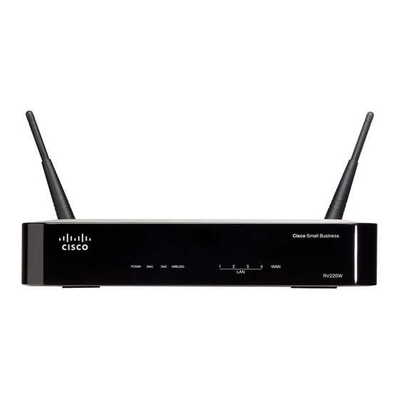
Physical Details Front-mounted LEDs POWER On - Power on. (Green) Off - No power. DIAG (Red) On - System problem. Off - Normal operation. Flashing - System rebooting or firmware upgrading. DMZ (Green) On - DMZ enabled. Off - DMZ disabled. WIRELESS On - Wireless enabled. -
Page 9: Rear Panel
Rear Panel RESET button The Reset button can be used in one of two ways: • If the Router is having problems connecting to the Internet, press the Reset button for just a second with a paper clip or a pencil tip. -
Page 10: Chapter 2 Installation
Chapter 2 Installation This Chapter covers the physical installation of the Dual-Band Wireless-N VPN Router. Requirements • Network cables. Use standard 10/100/1000BaseT network (UTP) cables with RJ45 con- nectors. • TCP/IP protocol must be installed on all PCs. • For Internet Access, an Internet Access account with an ISP, and a DSL connection. •... -
Page 11: Antennas And Positions
• The WAN LED may be OFF. After configuration, it should come ON. Antennas and Positions Positions The Router can be placed in three different positions: stackable, standalone, or wall-mount. Standalone 1. Locate the Router’s left side panel. 2. The Router includes two stands. With the two large prongs facing outward, insert the short prongs into the little slots in the Router, and push the stand upward until it snaps into place. -
Page 12: Chapter 3 Setup
Chapter 3 Setup This Chapter provides Setup details of the Dual-Band Wireless-N VPN Router. Configuration Program The Dual-Band Wireless-N VPN Router contains an HTTP server. This enables you to connect to it, and configure it, using your Web Browser. Your Browser must support JavaScript. The configuration program has been tested on the following browsers: •... - Page 13 Figure 1: Login Screen If you can't connect If the Dual-Band Wireless-N VPN Router does not respond, check the following: • The Dual-Band Wireless-N VPN Router is properly installed, LAN connection is OK, and it is powered ON. You can test the connection by using the "Ping" command: •...
-
Page 14: Setup Tab
Setup Tab The Setup screen contains all of the Router’s basic setup functions. The Router can be used in most network settings without changing any of the default values. Some users may need to enter additional information in order to connect to the Internet through an ISP (Internet Service Provider) or broadband (DSL, cable modem) carrier. - Page 15 Data - Summary Screen System Information It displays the current firmware version installed on this Router. Firmware Ver- sion Displayed here are the type and speed of the processor installed on the Router. System Up Time This is the length of time in days, hours, and minutes that the Router has been active.
-
Page 16: Setup - Wan Screen
Setup - WAN Screen DHCP By default, the Router’s Configuration Type is set to Automatic Configuration - DHCP, and it should be kept only if your ISP supports DHCP or you are connecting through a dynamic IP address. Figure 3: DHCP Screen Optional Settings Host Name Enter a host name for the Router. - Page 17 up with TZO. • Status - The status of the TZO service connection is displayed here. Connect When DDNS is enabled, the Connect button is displayed. Use this button to Button manually update your IP address information on the DDNS server. The Status area on this screen also updates.
- Page 18 PPPoE Most DSL-based ISPs use PPPoE (Point-to-Point Protocol over Ethernet) to establish Internet connections. If you are connected to the Internet through a DSL line, check with your ISP to see if they use PPPoE. If they do, you will have to enable PPPoE. Figure 5: PPPoE PPPoE Settings Username...
- Page 19 PPTP Point-to-Point Tunneling Protocol (PPTP) is a service that applies to connections in Europe and Israel only. Figure 6: PPTP PPTP Settings IP Address This is the Router’s IP address, when seen from the WAN, or the Internet. Your ISP will provide you with the IP Address you need to specify here. Subnet Mask This is the Router’s Subnet Mask.
- Page 20 tion terminates in the Max Idle Time field. Use this option to minimize your DSL connection time if it is charged based on time. This option allows the Router will periodically check your Internet con- Keep Alive nection. If you are disconnected, then the Router will automatically re- establish your connection.
- Page 21 Enter the IP address of the L2TP server L2TP Server Enter the User Name provided by your ISP. Username Password Enter the Password provided by your ISP. Connect on You can configure the Router to cut the Internet connection after it has Demand been inactive for a specified period of time (Max Idle Time).
-
Page 22: Setup - Lan Screen
Setup - LAN Screen The LAN Setup section allows you to change the Router’s local network settings for the four Ethernet ports. Figure 8: LAN Screen Data - LAN Screen IPv4 Enter the IPv4 address on the LAN side. The default value is Local IP Address 192.168.1.1. - Page 23 Select the subnet mask from the drop-down menu. The default value is Subnet Mask 255.255.255.0. Server Settings (DHCP) DHCP Server DHCP is enabled by default. If you already have a DHCP server on your network, or you don't want a DHCP server, then select Disabled (no other DHCP features will be available).
- Page 24 DHCPv6 Enabled or Disabled as required. DHCPv6 Lease Time Enter the desired value. The default is 0, which actually means one day. DHCP address Enter the start IP address of the DHCP range. range start DHCP address Enter the end IP address of the DHCP range. range end Primary DNS Your ISP will provide you with at least one DNS (Domain Name...
-
Page 25: Setup - Dmz Screen
Setup - DMZ Screen The DMZ screen allows one local PC to be exposed to the Internet for use of a special-purpose service, such as Internet gaming and video-conferencing. DMZ hosting forwards traffic to all the ports for the specified PC simultaneously, unlike Port Range Forwarding that can only forward a maximum of 10 ranges of ports. -
Page 26: Setup - Mac Address Clone Screen
Setup - MAC Address Clone Screen Some ISPs require that you register a MAC address. This feature clones your PC network adapter's MAC address onto the Router, and prevents you from having to call your ISP to change the registered MAC address to the Router's MAC address. The Router's MAC address is a 6-byte hexadecimal number assigned to a unique piece of hardware for identification. -
Page 27: Setup - Advanced Routing Screen
Setup - Advanced Routing Screen Figure 11: Advanced Routing Screen Data - Advanced Routing Screen Operating Mode • Gateway - This is the normal mode of operation. This allows all Operating Mode devices on your LAN to share the same WAN (Internet) IP ad- dress. - Page 28 Static Routing Sometimes you will prefer to use static routes to build your routing Select Set Number table instead of using dynamic routing protocols. Static routes do not require CPU resources to exchange routing information with a peer router. You can also use static routes to reach peer routers that do not support dynamic routing protocols.
-
Page 29: Setup - Time Screen
Setup - Time Screen You can either define your Router’s time manually or automatically through Time Server. Figure 13: Time Screen Data - Time Screen Time • Set the local time Manually - If you wish to enter the time and Time date manually, enter the Day, Month, Year, Hour, Minute, and Second in the Time field using 24 hour format (example 10:00pm... -
Page 30: Setup - Ip Mode Screen
Setup - IP Mode Screen You can either define your Router’s time manually or automatically through Time Server. Figure 14: IP Mode Screen Data - IP Mode Screen IP Mode This option utilizes IPv4 on the Internet and local network. IPv4 Only Dual-Stack IP This option utilizes IPv4 over the Internet and IPV4 and IPv6 on the... -
Page 31: Wireless - Basic Settings Tab
Wireless - Basic Settings Tab The Dual-Band Wireless-N VPN Router's settings must match the other Wireless stations. Note that the Dual-Band Wireless-N VPN Router will automatically accept both 802.11b and 802.11g connections, and no configuration is required for this feature. To change the Dual-Band Wireless-N VPN Router's default settings for the Wireless Access Point feature, use the Wireless link on the main menu to reach the Wireless screen. - Page 32 Wireless Net- Select the desired mode: work Mode • 2.4GHz Wireless • B-Only - All the wireless client devices can be connected to the Wireless Router at Wireless-B data rates with a maximum speed of 11Mbps. • G-Only - Both Wireless-N and Wireless-G client devices can be connected at Wireless-G data rates with a maximum speed of 54Mbps.
-
Page 33: Wireless - Security Settings
Wireless - Security Settings Change the Wireless Router’s wireless security settings on this screen. Figure 16: Disabled Data - Security Settings Screen WEP Data Encryption Select the desired SSID from the drop-down list. Select SSID Wireless Isola- Select Enabled to use this feature. tion (Between SSID w/o VLAN) Security Mode... - Page 34 Figure 17: WEP Data - WEP Screen WEP Data Encryption Normally, this should be left at the default value of "Automatic". If Authentication Type changed to "Open System" or "Shared Key", ensure that your Wireless Stations use the same setting. WEP Data Select the desired option, and ensure the Wireless Stations use the same setting.
- Page 35 WPA-Personal Figure 18: WPA-Personal Data - WPA-Personal Screen Encryption The WPA-Personal standard allows different encryption methods to be used. Select the desired option. Wireless Stations must use the same encryption method. Enter a WPA Shared Key of 8-63 characters. Shared Secret Key Renewal Enter a Key Renewal Timeout period, which instructs the Wireless Router how often it should change the encryption keys.
- Page 36 WPA2-Personal Figure 19: WPA2-Personal Data - WPA2-Personal Screen Encryption The WPA2-Personal standard allows different encryption methods to be used. Select the desired option. Wireless Stations must use the same encryption method. Shared Secret Enter a WPA Shared Key of 8-63 characters. Key Renewal Enter a Key Renewal Timeout period, which instructs the Wireless Router how often it should change the encryption keys.
- Page 37 WPA-Enterprise Figure 20: WPA-Enterprise Data - WPA-Enterprise Screen WPA offers you two encryption methods, TKIP and AES for data Encryption encryption. Select the type of algorithm you want to use, TKIP or AES. Enter the server address here. RADIUS Server RADIUS Port Enter the port number used for connections to the Radius Server.
- Page 38 WPA2-Enterprise Figure 21: WPA2-Enterprise Data - WPA2-Enterprise Screen Encryption WPA2 always uses AES for data encryption. Enter the server address here. RADIUS Server RADIUS Port Enter the port number used for connections to the Radius Server. Shared Key Enter the shared key. Data is encrypted using a key derived from the network key.
-
Page 39: Radius Server
Radius Server Figure 22: Radius Server Data - Radius Server Screen RADIUS Server Enter the server address here. Enter the port number used for connections to the Radius Server. RADIUS Port Shared Key Enter the shared key. Data is encrypted using a key derived from the network key. - Page 40 Select one of the keys to be used for data encryption (when you TX Key manually enter multiple keys).
-
Page 41: Wireless - Connection Control
Wireless - Connection Control This screen allows you to configure the Connection Control List to either permit or block specific wireless client devices connecting to (associating with) the Wireless Router. Figure 23: Connection Control Data - Connection Control Select SSID Select the desired SSID from the drop-down list. - Page 42 Figure 24: Wireless Client List...
-
Page 43: Wireless - Advanced Settings
Wireless - Advanced Settings This screen allows you to configure the advanced settings for the Wireless Router. The Wire- less-N Router adopts several new parameters to adjust the channel bandwidth and guard intervals to improve the data rate dynamically. Linksys recommends to let your Wireless Router automatically adjust the parameters for maximum data throughput. - Page 44 Message (TIM). The default is 100 Msec. DTIM Interval This value indicates how often the Wireless Router sends out a Deliv- ery Traffic Indication Message (DTIM). Lower settings result in more efficient networking, while preventing your PC from dropping into power-saving sleep mode.
-
Page 45: Wireless - Vlan & Qos
Wireless - VLAN & QoS This screen allows you to configure the Qos and VLAN settings for the Router. The QoS (Quality of Service) feature allows you specify priorities for different traffic. Lower priority traffic will be slowed down to allow greater throughput or less delay for high priority traffic. The 802.1Q VLAN feature is allowing traffic from different sources to be segmented. - Page 46 queues based on QoS settings (in IP or layer 2 header). WMM pro- vides the capability to prioritize traffic in your environment. The default is Enabled.
-
Page 47: Firewall Tab
Firewall Tab The Firewall Tab allows you to configure software security features like SPI (Stateful Packet Inspection) Firewall, IP based Access List, restriction LAN users on Internet (WAN port) access, and NAPT (Network Address Port Translation) Settings (only works when NAT is enabled) to limited services to specific ports. - Page 48 could place security concern to your PCs on the LAN side. You have to balance your needs on those applications and security. The default is unselected. • Java: Java is a programming language for websites. If you deny Java, you run the risk of not having access to Internet sites created using this programming language.
-
Page 49: Firewall - Ip Based Acl
Firewall - IP Based ACL This screen shows a summary of configured IP based Access List. The Access List is used to restrict traffic going through the Router either from WAN or LAN port. There are two ways to restrict data traffic. You can block specific types of traffic according to your ACL definitions. Or you can allow only specific types of traffic according to your ACL definition. -
Page 50: Edit Ip Acl Rule
Enable This tells the Router if the rule is active or not. You can have rules defined in the ACL Table but in an inactive state. The administrator can decide on when to enable specific ACL rules manually. Action This defines how the rule is to affect the traffic. It can be either Allow or Deny. - Page 51 Figure 29: Edit IP ACL Rule New Rule Action Select either Allow or Deny. Default is Allow. Service Select ALL or pre-defined (or user-defined) services from the drop- down menu. If checked, this ACL rule will be logged when a packet match hap- pens.
-
Page 52: Firewall - Internet Access Policy
Firewall - Internet Access Policy Access to the Internet can be managed by policies. A policy consists of four components. You need to define the PCs (MAC or IP address) to apply this policy, either Deny or Allow Internet service, what time and date to enable this policy, and what URLs or Keywords to apply this policy. - Page 53 Figure 30: Internet Access Policy Screen On the List of PCs screen, you can define PCs by MAC Address or IP Address. You can also enter a range of IP Addresses if you want this policy to affect a group of PCs. To create an Internet Access policy: 1.
- Page 54 6. Decide what Days and what Times you want this policy to be enforced. Select the individ- ual days during which the policy will be in effect, or select Everyday. Enter a range of hours and minutes during which the policy will be in effect, or select 24 Hours. 7.
- Page 55 Figure 32: Internet Access PC List...
-
Page 56: Firewall - Single Port Forwarding
Firewall - Single Port Forwarding This is one of the NAPT (Network Address Port Translation) feature. Use the Single Port Forwarding screen when you want to open specific services (that use single port). This allows users on the Internet to access this server by using the WAN port address and the matched external port number. - Page 57 using the standard port 80.) Protocol Select the protocol used for this application, TCP and/or UDP. IP Address For each application, enter the IP address of the PC running the spe- cific server application. Select Enabled to enable port forwarding for the relevant server Enabled application.
-
Page 58: Firewall - Port Range Forwarding
Firewall - Port Range Forwarding This is one of the NAPT (Network Address Port Translation) features. The Port Range For- warding screen allows you to set up public services on your network, such as web servers, ftp servers, e-mail servers, or other specialized Internet applications that use one or multiple port numbers (e.g. -
Page 59: Firewall - Port Range Triggering
Firewall - Port Range Triggering This is one of the NAPT (Network Address Port Translation) feature. Port Range Triggering is used for special applications that can request a port to be opened on demand. For this feature, the Wireless Router will watch outgoing packets for specific port numbers. This will trigger the Wireless Router to allow the incoming packets within the specified forwarding range and forward those packets to the triggering PC. -
Page 60: Security Protection - Web Protection
Security Protection - Web Protection The Web Protection features are provided by the Router. Configure the website filtering settings on this screen. Figure 36: Web Protection... - Page 61 Web Protection To filter website addresses (URLs), select this option. Enable URL Filtering Enable Web To block potentially malicious websites, select this option. Reputation URL Filtering The Router counts the number of attempted visits to a restricted URL. Reset Counter To reset the counter to zero, click Reset Counter.
- Page 62 Enter the appropriate IP addresses or ranges. Separate multiple URLs Addresses/range with semicolons (“;”). For a range of IP addresses, use a hyphen (“-”). Example: 10.1.1.0-10.1.1.10. Add>> To add the IP addresses or ranges, click Add. The IP addresses or range of trusted clients are displayed. To delete Approved Clients list an IP address or range, click its trash can icon.
-
Page 63: Security Protection - Email Protection
Security Protection - Email Protection The Email Protection features are provided by an online service called IMHS, which stands for InterScan™ Messaging Hosted Security. It checks your e-mail messages so spam, viruses, and inappropriate content are filtered out. After you have configured the IMHS settings, your email messages will be checked online before appropriate messages are forwarded to your network. -
Page 64: Security Protection - License
Security Protection - License The license for the Trend Micro ProtectLink Gateway service (Email Protection and Web Protection) is valid for one year from the time the activation code for Web Protection is gener- ated. If you do not provide the necessary information to activate Email Protection during registration, please provide that information as soon as possible because Email Protection and Web Protection will expire at the same time. - Page 65 seats to your license, click Add Seats. Then follow the on-screen instructions.
-
Page 66: Vpn - Summary Tab
VPN - Summary Tab Figure 39: Summary Screen Summary Tunnel(s) Used Displays the number of tunnels used. Tunnel(s) Avail- Displays the number of available tunnels. able Tunnel Status Displays the number of the tunnel. Name Displays the name of the tunnel, as defined by the Tunnel Name field on the VPN >... - Page 67 VPN Clients Status Displays the user number from 1 to 5. Username Displays the username of the VPN Client. Status Displays the connection status of the VPN Client. IP Address Displays the IP address of the VPN Client. Start Time Displays the start time of the most recent VPN session for the specified VPN Client.
-
Page 68: Vpn - Ipsec Vpn Tab
VPN - IPSec VPN Tab Use this screen to create VPN tunnels between the Router to the remote Router. All Linksys Routers with Ipsec VPN support can be used as a remote Router (e.g. RVS4000, WRV54G, RV042). The Router supports VPN tunnels using IPsec (IP Security) technologies. You can create, delete, or modify a VPN tunnel on this page. - Page 69 Select Enable to enable this tunnel. Tunnel Enable Local Security Group Local Security This has two settings, IP Only and IP + Domain Name (FQDN) Gateway Type Authentication. • IP Only If this is selected, the Wireless Router’s WAN IP address automatically appears in the IP Address field.
- Page 70 key negotiation is needed. Basically, manual key management is used in small static environments or for troubleshooting purpose. Notice that both sides must use the same Key Management method (both Auto or both Manual). For Manual key management, all the configurations need to match on both sides.
- Page 71 method. • Phase 1 Authentication Authentication determines a method to authenticate the data packets to make sure they come from a trusted source. Either MD5 or SHA1 may be selected. Notice that both sides (VPN endpoints) must use the same Authentication method. •...
- Page 72 • PreShared Key IKE uses the Pre-shared Key field to authenticate the remote IKE peer. Both characters and hexadecimal values are accept- able in this field. e.g. “My_@123” or “0x4d795f40313233” Note that both sides must use the same Pre-shared Key. Advanced There are two types of Phase 1 exchanges: Main mode and Aggres- Aggressive Mode...
-
Page 73: Vpn - Vpn Client Accounts Tab
VPN - VPN Client Accounts Tab You can allow remote users to easily establish a VPN connection to your Router using the Linksys QuickVPN client utility without using a compatible VPN Router with IPsec VPN settings. This is achieved by creating user accounts on the Router and authenticate users through Username and Password. - Page 74 VPN Client List Table Displays the user number. Active When checked, the designated user can connect, otherwise the VPN client account is disabled. Username Displays the username. Password Displays the password. This button is used to modify the username, password, or toggle Edit Button between whether the user is allowed to change their password.
-
Page 75: Vpn - Vpn Passthrough
VPN - VPN Passthrough Figure 42: VPN Passthrough Screen VPN Passthrough IPSec Internet Protocol Security (IPSec) is a suite of protocols used to PassThrough implement secure exchange of packets at the IP layer. IPSec Passthrough is enabled by default to allow IPSec tunnels to pass through the Router. -
Page 76: Qos Tab
QoS Tab QoS (Quality of Service) allows you to perform Bandwidth Management, by either Rate Control or Priority. You can also configure QoS Trust Mode and the DSCP settings. QoS - Bandwidth Management Figure 43: Bandwidth Management Screen Setup QoS (Quality of Service) is disabled by default. When enabled, this Bandwidth option allows you to assign priority based on the application type. - Page 77 Enter the minimum rate for the guaranteed bandwidth. Mini. Rate Enter the maximum rate for the guaranteed bandwidth. Max. Rate Enable Check this box to enable this Rate Control Rule. Add to List After a rule is set up, click this button to add it to the list. The list can contain a maximum of 15 entries.
-
Page 78: Qos - Qos Setup
QoS - QoS Setup The QoS Setup screen allows users to configure QoS Trust Mode for each LAN port. Figure 45: QoS Setup Screen QoS Setup The number of the LAN port. Port ID Trust Mode Select either CoS or DSCP. The default is CoS. Priority If Trust Mode is set to Port, select the port priority from 0 to 7 from the drop-down menu. -
Page 79: Qos - Queue Settings
QoS - Queue Settings Figure 46: Queue Settings QoS Setup Queue Settings Queue The number of the Queue. Strict Priority Select either Strict Priority or WRR. The default is Strict Priority. If WRR enabled, enter the values for WRR Weight and % of WRR Bandwidth. -
Page 80: Qos - Dscp Setup
QoS - DSCP Setup Figure 47: DSCP Setup Screen DSCP Setup The Differentiated Services Code Point value in the incoming packet. DSCP Priority Select the traffic forwarding queue, 1 to 7, to which the DSCP priority is mapped. Restore Defaults Click this button to restore the default DSCP values. -
Page 81: Administration Tab
Administration Tab The Administration tab provides access to system administration settings and tools. Administration - Management Figure 48: Management Screen Local Gateway Access Select the desired Gateway User List. Gateway Userlist Enter the user name here. Gateway Username Enter the password. Gateway Password Re-enter to Con- Retype the password in this field. - Page 82 Write Community Enter the SNMP community name for SNMP “Set” commands. Enter the SNMP community name for SNMP “Trap” commands. Trap Community Trap To Enter the IP Address of the SNMP Manager to which traps will be sent. If desired, this may be left blank. UPnP UPnP If you want to use UPnP, keep the default setting, Enable.
-
Page 83: Administration - Log
Administration - Log Figure 49: Log Screen Log Setting Log Level Select the log level(s) that the Router should record. Outgoing Log Select Enable to cause all outgoing packets to be logged. You can then click View Outgoing Table to display information on the outgoing packets including Source IP, Destination IP, and Ser- vice/Port number. - Page 84 Denial of Service Enter the number of DoS (Denial of Service) attacks which need to Thresholds be blocked by the built-in Firewall before an e-mail alert is sent. The minimum value is 20, the maximum value is 100. Log Queue Length The default is 0 entries (Router will e-mail the log if there are more than 50 entries).
-
Page 85: Administration - Diagnostic
Administration - Diagnostic Figure 50: Diagnostic Screen Ping Test Parameters Ping Target IP Enter the IP address or URL that you want to ping. Ping Size Enter the size of the packet you want to use. Number of Pings Enter the number of times you wish to ping the target device. Enter the time period (milliseconds) between each ping. - Page 86 Pair Identifies a specific pair (A, B, C, or D) in the cable. Each cable consists of 8 pins (4 pairs). Cable Length Displays the length of the cable in meters. Displays the status of the pair. Status...
-
Page 87: Administration - Backup & Restore
Administration - Backup & Restore Figure 51: Backup & Restore Screen Backup & Restore Backup & Restore To download a copy of the current configuration and store the file on your PC, click Backup to start the download. Restore & Configuration To restore a previously saved config file back to the Router, enter Restore &... -
Page 88: Administration - Factory Defaults
Administration - Factory Defaults Figure 52: Factory Defaults Screen Factory Defaults Click this button to reset all configuration settings to their factory Restore Factory Defaults Button default values. Any settings that have been saved will be lost when the default settings are restored. After clicking the button, another screen will appear. -
Page 89: Administration - Reboot
Administration - Reboot Figure 53: Reboot Screen Reboot Click this button to reboot the Router. This operation will not cause Reboot the Router to lose any of its stored settings. -
Page 90: Administration - Firmware Upgrade
Administration - Firmware Upgrade To upgrade firmware, download the latest firmware for the product from www.linksys.com, extract it to your computer, and perform the steps below. Figure 54: Firmware Upgrade Screen Firmware Upgrade File Type in the name of the extracted firmware upgrade file or click Browse to locate the file. -
Page 91: L2 Switch - Create Vlan
L2 Switch - Create VLAN VLANs are logical subgroups of a Local Area Network (LAN) created via software rather than defining a hardware solution. VLANs combine user stations and network devices into a single domain regardless of the physical LAN segment to which they are attached. VLANs allow network traffic to flow more efficiently within subgroups. -
Page 92: L2 Switch - Vlan & Port Assignment
L2 Switch - VLAN & Port Assignment Figure 56: VLAN & Port Assignment Screen Port Settings Port Mode The table indicates each port’s current mode (Access, Trunk, or General e). Wireless can be enabled in Access Mode. Acceptable Ingress Configure which kind of packet can be accepted in the port. Frame Type Ingress Filtering Select the checkbox if you want to use Ingress Filtering. -
Page 93: L2 Switch - Radius
L2 Switch - Radius Figure 57: Radius Screen Radius Select Enabled or Disabled from the drop-down menu to enable or Mode disable RADIUS. Radius IP Enter the Server IP address. Radius UDP Port Enter the UDP port. The UDP port is used to verify the RADIUS server authentication. -
Page 94: L2 Switch - Port Setting
L2 Switch - Port Setting Figure 58: Port Setting Screen Port Setting Port Displays the physical port number. Link Displays the port duplex mode and speed. Full Duplex indicates that the interface supports transmission between the device and its link partner in both directions simultaneously. -
Page 95: L2 Switch - Statistics
Setup L2 Switch - Statistics Figure 59: Statistics Screen Statistics Displays the number of Bytes transmitted from the selected port. Tx Bytes Tx Frames Displays the number of Frames transmitted from the selected port. Rx Bytes Displays the number of Bytes received on the selected port. Displays the number of Frames received on the selected port. -
Page 96: L2 Switch - Port Mirroring
L2 Switch - Port Mirroring Figure 60: Port Mirroring Screen Mirror Configuration Mirror Source Use this to enable or disable source port mirroring for each port on the Router. To enable source port mirroring on a port, check the box next to that port. -
Page 97: Status - Gateway
Status - Gateway Figure 61: Gateway Screen WAN/Gateway Firmware Version Displays the Gateway’s current firmware. Mac Address Displays the Gateway MAC Address, as seen by your ISP. Displays the time, based on the time zone you selected on the Setup Current Time tab. - Page 98 DHCP. IP Conntrack Click this button to display the IP Conntrack screen. IP Conntrack Figure 62: IP Conntrack The IP Conntrack (Connection Tracking) screen displays information about TCP/UDP connec- tions, such as source and destination IP address and port number pairs (known as socket pairs), protocol types (TCP/UDP/ICMP), connection state and timeouts.
-
Page 99: Status - Local Network
Status - Local Network Figure 63: Local Network Screen Local Network This shows the current system. Current IP Ad- dress System Mac Address This is the Router MAC Address, as seen on your local, Ethernet network. IP Address The Internet IP Address is displayed here. This Subnet Mask is associated with the IP address above. - Page 100 Figure 64: DHCP Client Table Figure 65: ARP/RARP Table...
-
Page 101: Status - Wireless Lan
Status - Wireless LAN This screen provides some basic information on the Wireless LAN of this Wireless Router. Figure 66: Wireless LAN Screen Wireless LAN Displays the IP address on the Wireless LAN interface. Wireless IP Ad- dress Displays the MAC address on the Wireless LAN interface. Mac Address Network Mode Displays the Wireless network operating mode (e.g. -
Page 102: Status - System Performance
Status - System Performance This screen provides data packet statistics on the LAN switch and Wireless LAN of the Router. Figure 67: System Performance Screen All LAN ports / WLAN Packets Received This shows the number of packets received. This shows the number of packets sent. Packets Sent Bytes Received This shows the number of bytes received. -
Page 103: Appendix A Specifications
Appendix A Specifications Dual-Band Wireless-N VPN Router General Model RV220W Ports 10/100/1000 Base-T Ethernet, 12V DC Power Buttons Reset Cabling Type Type UTP CAT 5 LEDs Power, Diag, DMZ, Wireless, ETHERNET 1-4, Internet Wireless IEEE 802.11a: 23.92 dBm Transmit Power draft 802.11n Standard-20 MHz Channel mode: 24.52 dBm draft... - Page 104 Setup/Config Web User Interface WebUI Built in Web UI for Easy browser-based configuration (HTTP/HTTPS) Management SNMP Version SNMP Version 1, 2c Event Logging Local, Syslog, E-mail Alerts Web F/W upgrade Firmware Upgradable Through Web-Browser Diagnostics DIAG LED for Flash and RAM failure; Ping Test for network diagnostics Security 5 QuickVPN Tunnels for remote client access...
- Page 105 Environment Device Dimensions (W x H x D) 170 x 131 x 170 mm Weight 0.99 lbs (0.45kg) Power 12V 1.25A Certification FCC class B, CE, ICES-003 Operating Temp. 0ºC to 40ºC (32ºF to 104ºF) Storage Temp. -20ºC to 70ºC (-4ºF to 158ºF) Operating Humidity 10% to 85% Non-Condensing Storage Humidity...