Sony VENICE MPC-3610 Operating Instructions Manual
Digital motion picture camera
Hide thumbs
Also See for VENICE MPC-3610:
- Operating instructions manual (92 pages) ,
- Operating instructions manual (116 pages) ,
- Update manual (17 pages)

Related Manuals for Sony VENICE MPC-3610


Summary of Contents for Sony VENICE MPC-3610
- Page 1 4-735-109-11 (1) Digital Motion Picture Camera VENICE Operating Instructions MPC-3610 Firmware Version 1.0 © 2017 Sony Corporation...
-
Page 2: Table Of Contents
000 2 Table of Contents 1. Overview 4. Shooting Features ................3 Basic Operations ...............57 System Configuration ............5 Useful Functions ...............58 Location and Function of Parts .......... 6 5. Connecting External Devices 2. Preparation Connecting External Monitors and Recording Devices ..............59 Preparing a Power Supply ..........14 External Synchronization ..........61... -
Page 3: Overview
The silent-running fan can be cleaned or even Assistant side of the camera for fast access to the Sony’s S-Gamut3.Cine color space together with swapped out on set quickly and easily to maintain camera settings by the camera assistant while S-Log3. - Page 4 1. Overview: Features Effective Picture Size Software Licenses The unit supports shooting in the following effective picture sizes. You can select software licenses (optional) according to the intended usage of the unit. Software licenses are installed using Maintenance > License Options (page 51) in the full menu. [Note] A software license is required to shoot in 6K 3:2 and 4K 4:3.
-
Page 5: System Configuration
1. Overview System Configuration Microphone Holder (A-2182-620-A) Rod Clamp (A-2182-621-A) Rod (4-684-612-01) DVF-EL200 DVF-L700 ECM-680S, ECM-678, Viewfinder Viewfinder ECM-674 (VF cable (A-2201-632-A or Microphone A-2201-633-A) is required) (EC-0.5X3F5M is required) AXS-R7 AXS-A256S24, AXS-A512S48, AXS-AR1, AXS-CR1 Portable Memory AXS-A512S24, AXS-A1TS48, AXS Memory Card Recorder AXS-A1TS24 Reader... -
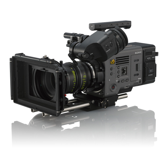
Page 6: Location And Function Of Parts
1. Overview Location and Function of Parts Power switch ASSIGN (assignable) lamp 3 (page 32) Operator Side Set to the ON position () to turn the power on. The lamp is lit orange when the assigned Set to the OFF position () to turn the power function is on (enabled) or activated, and not off. - Page 7 1. Overview: Location and Function of Parts the tape measure hook as a reference. You can SxS memory card slot block (page 21) Assistant Side attach the end of a tape measure to the hook, and measure the distance from the subject. The SxS memory card slots are located behind the cover.
- Page 8 1. Overview: Location and Function of Parts AUDIO IN connector (XLR 5-pin) USER button Front Input external microphone or audio Press to display the user function list on the equipment signals. sub display, and to operate the ITEM keys 1 to When the audio source is set to LINE or MIC 5 user function buttons.
- Page 9 1. Overview: Location and Function of Parts Digital signal and analog signal input are Rear supported. Digital signal: 1.5G HDSDI interlaced signal Analog signal: HD sync, Analog TC IN (timecode input) connector (BNC type) To lock the timecode of the unit to an external source, input a reference timecode signal.
- Page 10 1. Overview: Location and Function of Parts Bottom 1 2 3 Air vent External device connector Tripod plate attachment holes Not supported in firmware version 1.0. Type of screw: 1/4-20UNC (2) Type of screw: 3/8-16UNC (4) Release button (page 16) Length of engagement: 9 mm (3/8 inch) or less Handle/VF attachment mount (page 16) Bottom cover...
- Page 11 1. Overview: Location and Function of Parts Exposure index indicator Monitor LUT indicator Viewfinder Screen Displays the exposure index (EI) value. Displays the LUT setting of the Monitor output (page 42). Color temperature indicator During shooting (recording or standby) and playback, the status and settings of the unit are Displays the color temperature and Tint value HDMI LUT indicator superimposed over the picture on the viewfinder screen.
- Page 12 1. Overview: Location and Function of Parts SDI output REC trigger indicator Iris position indicator Displays the SDI output REC trigger status. Displays the iris position (only when a lens that is compatible with the iris setting display function is attached). State Display Technical >...
- Page 13 1. Overview: Location and Function of Parts Information displayed on the playback screen The following information is displayed on the playback picture. 12:34:56:00 A001C001 Play XCON ST Time data display Audio level meter indicators Displays the duration or timecode, depending Displays the levels of audio channels 1 and 2 on the TC/Media category >...
-
Page 14: Preparation
You can use a battery pack or AC power via an AC If the remaining battery charge becomes low adaptor. For safety, use only the Sony battery packs and AC If the remaining battery charge decreases to a adaptors listed below. -
Page 15: Setting The Clock
2. Preparation Setting the Clock When you use the unit for the first time, the initial setup screen appears on the sub display when the power is turned on. Set the date and time of the built-in clock using this display. Time Zone The value shows the time difference from UTC (Coordinated Universal Time). -
Page 16: Attaching The Vf Attachment And Handle
2. Preparation Attaching the VF Attachment and Handle Attaching the VF Attachment Attaching the Handle Slide the VF attachment on in the direction of Slide the handle on in the direction of the the arrow to attach it. arrow to attach it. Position the VF attachment in the desired Position the handle in the desired front/rear front/rear position, then turn the lock lever to... -
Page 17: Mounting A Lens And Adjusting The Flange
There are two connectors on the side of For details about available lenses for the unit, contact a Sony You can adjust the thickness by ±0.1 mm in 0.01 service representative. - Page 18 2. Preparation: Mounting a Lens and Adjusting the Flange Focal Length Adjusting the flange focal length Cleaning the Filter Reattach the PC connectors (two locations) to their original positions, and tighten the four Phillips screws with 0.18 N·m tightening Remove the six Torx screws and remove the PL To clean the filter, first remove the adaptor.
-
Page 19: Attaching A Viewfinder
2. Preparation Attaching a Viewfinder Available viewfinders for the unit Clamper Attaching a Viewfinder Adjusting the Viewfinder Position DVF-EL200: OLED color viewfinder DVF-L700: LCD color viewfinder Align the viewfinder shoe with the groove of To adjust the front/rear position the viewfinder mount on the VF attachment, Viewfinders are available separately. - Page 20 2. Preparation: Attaching a Viewfinder To adjust the left/right position and height To adjust the viewfinder angle (angle) You can adjust the angle of the viewfinder while shooting. Loosen the rod lock lever at the front of the VF Loosen the rotation lock lever on the attachment.
-
Page 21: Handling Sxs Memory Cards
2. Preparation Handling SxS Memory Cards ˎ SxS, SxS PRO, and SxS-1 are trademarks of Sony ˎ This unit records audio and video on SxS memory Inserting an SxS Memory Card Removing an SxS Memory Card cards (optional) loaded in the card slots. - Page 22 2. Preparation: Handling SxS Memory Cards Media recorded with a device other than this unit or with Formatting while recording Formatting (Initializing) SxS Memory Restoring an SxS Memory Card another unit of different version (even of the same model) may not be restored using this unit. Cards Even while recording, the SxS memory card loaded in the other card slot can be formatted.
-
Page 23: Handling Sd Cards For Saving Configuration Data
2. Preparation Handling SD Cards for Saving Configuration Data You can store the configuration file of the camera [Note] Removing an SD Card All data is erased when an SD card is formatted, and the data on an SD card (optional). The stored file can be cannot be restored. -
Page 24: Using With Axs-R7
2. Preparation Using with AXS-R7 You can record video/audio in RAW or X-OCN Docking module Inserting an AXS Memory Card Removing an AXS Memory Card to an AXS-R7 AXS (Access Memory Card System) Recorder (optional) by attaching the recorder to the unit. - Page 25 2. Preparation: Using with AXS-R7 Formatting (Initializing) an AXS Checking the Remaining Recording Restoring an AXS Memory Card Memory Card Time If for any reason an error should occur in a memory card, the card must be restored before use. AXS memory cards must be formatted the first While shooting (recording or standby), you If an AXS memory card that needs to be restored...
-
Page 26: Sub Display
000 26 3. Camera Operations Sub Display The sub display displays the Home screen, clip list screen, playback screen, menu screen, full menu screen, and user functions screen. You can switch between the screens on the sub display using the buttons on the Assistant side of the unit. User functions screen User 1 User 2... - Page 27 3. Camera Operations: Sub Display Status display area Home Screen Press the HOME button on the Assistant side to display the Home screen. You can check the status of the unit and set basic settings for the unit on the Home screen. 00:00:00:00 23.98fps 3.8K 16:9...
- Page 28 3. Camera Operations: Sub Display Warning icon Displayed when other than a high temperature warning message is issued. The description is displayed in the Info category in the menu. Ext-LK icon Displayed when the internal timecode generator is locked to an external signal input to the TC IN (timecode input) connector.
-
Page 29: Operations On The Home Screen Of The Sub Display
3. Camera Operations Operations on the Home Screen of the Sub Display Changing the brightness of the sub display When setting White Balance Basic Operation Step Edit Operation You can change the brightness of the sub display On the White Balance settings edit screen, you using Technical >... - Page 30 3. Camera Operations: Operations on the Home Screen of the Sub Display Changing Preset Look LUT Operation Home Screen Items on the Sub Display You can set a LUT when Look is selected on the LUT selection screen using the Edit Look button The names of items and corresponding setting values are given below.
- Page 31 3. Camera Operations: Operations on the Home Screen of the Sub Display Item Description ND Filter Sets the ND filter position. The following settings are available. Clear/0.3/0.6/0.9/1.2/1.5/1.8/2.1/2.4 Configures settings related to the LUT to apply to the output video. Page 1 SDI 1/2 (ITEM key 2): Log Display only, as LUT cannot be applied to the SDI 1/2 output image.
-
Page 32: User Functions Screen
3. Camera Operations User Functions Screen You can press the USER button (page 8) to The following tables lists the functions that are assigned when the unit is shipped from the factory. Changing Button Functions display the user functions screen on the sub Button Function Assignable Button setting... - Page 33 3. Camera Operations: User Functions Screen Assignable Button Function State when unit is powered on Functions that can be Assigned to Assignable Buttons 1 to 4 setting SxS Slot Change Switches the active slot when two SxS memory Setting retained cards are inserted.
- Page 34 3. Camera Operations: User Functions Screen Assignable Button setting Function State when unit is powered on VF Focus Magnifier Turns the focus magnifier function of Setting not retained the viewfinder on/off. VF LUT bypass Disables the LUT applied to the Setting not retained viewfinder output image while the button is pressed, and sets Log...
-
Page 35: Menu Operations
3. Camera Operations Menu Operations By pressing the MENU button while shooting Basic Operation Turn the MENU dial to move the cursor to the (during recording or recording standby) or during setting value. playback, you can display and operate the menu screen on the sub display. - Page 36 3. Camera Operations: Menu Operations TC/Media category Menu Item List Default values are shown underlined and in bold text. The items available in each category are given below. Item Settings Description TC Mode Preset F-Run (Ext-Lk)/ Sets the timecode mode. Project category Preset R-Run/Int Regen...
- Page 37 3. Camera Operations: Menu Operations Item Settings Description Item Settings Description Format Media AXS Slot A Formats the AXS memory card in slot A. SDI 3/4 Output The available settings vary Selects the SDI 3/4 output format. (executed when Format depending on the SDI 1/2 AXS Slot B Formats the AXS memory card in slot B.
- Page 38 3. Camera Operations: Menu Operations Audio category Checking the Status using the Info Category Default values are shown underlined and in bold text. You can check the status of media and the battery, and check the contents of warnings and errors that Item Settings Description...
- Page 39 3. Camera Operations: Menu Operations Project Frame Rate Effective picture Main recording format SxS sub recording Recording Format Settings size (Imager Mode) format (Sub Rec AXS Rec Format SxS Rec Format Format) The following recording formats can be selected for different combinations of effective picture size and 4K 17:9 –...
- Page 40 3. Camera Operations: Menu Operations Project Frame Rate Effective picture Main recording format SxS sub recording size (Imager Mode) format (Sub Rec AXS Rec Format SxS Rec Format Format) 50/59.94 4K 17:9 – (4096×2160) 4K XAVC-I Class300 MPEG HD422 RAW/X-OCN –...
-
Page 41: Full Menu Operations
3. Camera Operations Full Menu Operations The full menu for configuring the required settings Controls Setting Menu Items for shooting and playback is displayed on the sub display be pressing and holding the MENU button for 2 seconds or longer. Turn the MENU dial to move the cursor to the menu item you want to set, then press the MENU MENU button (page 7) -
Page 42: Full Menu List
3. Camera Operations Full Menu List The functions and available settings of each menu item are given below. Shooting > White Balance Makes settings related to white balance. Menu item Settings Description Color Temp. Select 3200K+00/4300K+00/ Displays and selects the color temperature/color Shooting Menu 5500K+00 tone of the white balance. - Page 43 3. Camera Operations: Full Menu List Shooting > Look Project Menu Makes settings related to Preset Look. Menu item Settings Description Category Preset Look Displays the LUT category. Default values are shown underlined and in bold text. Preset Look Select s709/R709(800%) Selects the Preset Look.
- Page 44 3. Camera Operations: Full Menu List Project > All File TC/Media Menu Makes settings related to All-settings files. Menu item Settings Description Load SD Card Load an All-settings file from an SD card. Default values are shown underlined and in bold text.
- Page 45 3. Camera Operations: Full Menu List TC/Media > Format Media Monitoring Menu Formats media. Menu item Settings Description SxS Slot A Execute/Cancel Initializes the SxS memory card in slot A (execute Default values are shown underlined and in bold text. by selecting Execute).
- Page 46 3. Camera Operations: Full Menu List Monitoring > SDI OSD Monitoring > Status Info B Makes settings related to information and frame lines superimposed on the SDI output signal. Makes settings related to information displayed on the output image when Status Info Select is set to “Info.
- Page 47 3. Camera Operations: Full Menu List Monitoring > Frame Line Monitoring > VF Display Makes settings related to lines and markers displayed on the output image. Makes settings related to the viewfinder display. Menu item Settings Description Menu item Settings Description Color White/Yellow/Cyan/Green/...
- Page 48 3. Camera Operations: Full Menu List Audio > Audio Configuration Audio Menu Makes settings related to audio input/output. Menu item Settings Description MIC Input Mono/ Mono/Stereo Selects whether the front microphone is Default values are shown underlined and in bold text.
- Page 49 11.5V (0.1V increments) Sets the threshold value for displaying the “Battery Off in Rec/Auto: The fan is silent when recording, End” warning when using a Sony non-InfoLithium and operates automatically in response to the battery. internal temperature when not recording.
-
Page 50: Maintenance Menu
3. Camera Operations: Full Menu List Technical > DC Voltage Alarm Maintenance Menu Sets alarms relating to external DC supply voltage. Menu item Settings Description DC Low Voltage1 11.5V to 17V (0.1V increments) Sets the threshold value for displaying a low Default values are shown underlined and in bold text. - Page 51 3. Camera Operations: Full Menu List Maintenance > Reset to Default Returns the unit to factory default state. Menu item Settings Description Reset Execute/Cancel Initializes all unit settings (execute by selecting Execute). Maintenance > License Options Installs software options. Menu item Settings Description Install: <target_...
-
Page 52: Clip Operations
3. Camera Operations Clip Operations Clip operations are performed using the clip list screen and the playback screen. You can play a clip by Format (codec) selecting the clip to play from the clip list screen displayed on the sub display. Displays the recording format (codec) of the When AXS Rec Format is not set to Rec Off in the Project category in the menu, AXS media becomes clip indicated by the cursor. - Page 53 3. Camera Operations: Clip Operations Status display area Playback Screen The playback screen is displayed when you select a clip to play on the clip list screen and press the MENU dial or Play button (ITEM key 3). 00:00:00:00 23.98fps 3.8K 16:9 Function display area DC IN...
-
Page 54: Playback
3. Camera Operations Playback You can play recorded clips while the unit is in Playback operations Switching to an AXS memory card standby mode. Playback operation is performed using the buttons You can quickly play video recorded on an AXS [Note] on the sub display (page 53). -
Page 55: Operations On The Home Screen Of The Mini Display
3. Camera Operations Operations on the Home Screen of the Mini Display You can check the status of the unit and set basic Controls Basic Operation settings for the unit on the Home screen of the mini display. Press ITEM key 1, 2, or 3. Fixed HOME button (page 6) The cursor appears. - Page 56 3. Camera Operations: Operations on the Home Screen of the Mini Display Home Screen Items on the Mini Display The names of items and corresponding setting values are given below. Default values are shown underlined and in bold text. Item Description Displays the video frame rate.
-
Page 57: Shooting
000 57 4. Shooting Basic Operations Basic recording can be performed with the Clip names following procedures. Clip names are recorded using the “Cam ID + Make sure that the necessary devices are Reel#” format. The clip name is created according attached to the unit and power is supplied to to the following rules. -
Page 58: Useful Functions
4. Shooting Useful Functions Simultaneous Recording (Simul Rec) Recording Review (Rec Review) Focus Magnifier Function Viewfinder Double Speed Scan Function You can simultaneously record two sizes of You can review the last recorded clip on the By pressing the FOCUS MAG button of the pictures on an SxS memory card in one slot. -
Page 59: Connecting External Devices
000 59 5. Connecting External Devices Connecting External Monitors and Recording Devices To display the recording/playback image on an MONITOR OUT Connector (BNC Type) 12V OUT Connector (DC OUT 12V, 24V OUT Connector (DC OUT 24 V, external monitor, select the output signal and use an appropriate cable for the monitor to be Hirose 4-pin) Fischer 3-pin) - Page 60 5. Connecting External Devices: Connecting External Monitors and Recording Devices AUX Connector (LEMO 5-pin) Outputs the timecode signal. Signal Factory Use – TC OUT...
-
Page 61: External Synchronization
000 61 5. Connecting External Devices External Synchronization When shooting with multiple units, synchronized You can check the genlock status using Technical To release external lock Synchronizing the Timecode with recording can be performed using a specific > Genlock > Reference Lock Type (page 50) in reference signal to synchronize the timecode the menu. -
Page 62: Appendix
Contact a Sony service or sales representative for and scattered light. After use more information about inspections. - Page 63 6. Appendix: Usage Precautions White flecks LCD and OLED Panels Notes on the Display Output Voltages of the Unit Although the CMOS image sensors are produced with high-precision technologies, fine white ˎ Pictures on the viewfinder screen may be ˎ The LCD panel fitted to this unit is manufactured The total output power that can be supplied to flecks may be generated on the screen in rare...
-
Page 64: Recording Formats And Output Signals
6. Appendix Recording Formats and Output Signals SDI OUT Connector Output Formats The serial digital signal from an SDI OUT connector is output according to the Project category and Monitoring category settings in the menu. For details about Project category settings combinations, see “Recording Format Settings” (page 39). Default values are shown underlined and in bold text. - Page 65 6. Appendix: Recording Formats and Output Signals Project Monitoring > Output Format Output format Project Frame Rate Imager Mode SxS Rec Format SDI 1/2 SDI 3/4 SDI 1 SDI 2 SDI 3 SDI 4 23.98 6K 3:2/ XAVC-I 4K Class480/ 4096×2160P 2SI –...
- Page 66 6. Appendix: Recording Formats and Output Signals MONITOR OUT Connector/HDMI OUT Connector Output Formats The digital signal from the MONITOR OUT and HDMI OUT connectors is output according to the Project category and Monitoring category settings in the menu. For details about Project category settings combinations, see “Recording Format Settings” (page 39). Default values are shown underlined and in bold text.
- Page 67 6. Appendix: Recording Formats and Output Signals Project Monitoring > Output Format Output format Project Frame Rate Imager Mode SxS Rec Format SDI 1/2 SDI 3/4 Monitor HDMI Monitor Out HDMI 23.98 6K 3:2/ XAVC-I 4K Class480/ 4096×2160P 4096×2160P 4096×2160P 2SI –...
-
Page 68: Error/Warning Indications
Turn off the power and check the connected Condition in the menu. Follow the instructions provided to resolve the issue. equipment, cables, and media. If the error persists when the unit is turned on again, contact your Sony service Display indication Cause and Solution representative. - Page 69 AXS Recorder Fan Stopped The fan in the AXS-R7 that is connected to the unit has stopped. Avoid use under high temperature conditions. Remove the AXS-R7 from the unit and contact a Sony service representative. Unsupported FPS Unsupported AXS memory was detected.
-
Page 70: Items Saved In Files
6. Appendix Items Saved in Files Table legend Project Menu Yes: Saved No: Not saved –: Not saved (temporary setting) Item Sub-item File type Basic Setting Imager Mode Shooting Menu Project Frame Rate AXS Rec Format SxS Rec Format Item Sub-item File type Sub Rec Format... - Page 71 6. Appendix: Items Saved in Files TC/Media Menu Monitoring Menu Item Sub-item File type Item Sub-item File type Output Format SDI 1/2 Timecode Mode SDI 3/4 Manual Setting – Monitor Reset – HDMI TC Format VF OSD Status Info TC Source –...
-
Page 72: Audio Menu
6. Appendix: Items Saved in Files Item Sub-item File type Audio Menu Frame Line A Center Marker Aspect Ratio Item Sub-item File type Aspect Safety Zone Picture Area Audio Input CH-1 Audio Select Safety Zone CH-2 Audio Select User Frame Line CH-1 Audio Level Frame Line B Center Marker... - Page 73 – Unique Device ID – Battery Near End:Info Battery Firmware Camera – End:Info Battery – Near End:Sony Battery FW Update-camera – End:Sony Battery Near End:Other Battery End:Other Battery Detected Battery – DC Voltage Alarm DC Low Voltage1 DC Low Voltage2...
-
Page 74: Licenses
Open Software Licenses License GPL/LGPL Applies THIS PRODUCT IS LICENSED UNDER THE AVC On the basis of license contracts between Sony PATENT PORTFOLIO LICENSE FOR THE PERSONAL and the software copyright holders, this product THIS PRODUCT IS LICENSED UNDER THE MPEG-4... -
Page 75: Specifications
6. Appendix Specifications XAVC-I Class480: General Specifications Camera Input/Output 4K: 4096×2160 29.97P/25P/24P/23.98P QFHD: 3840×2160 Mass Approx. 3.9 kg (8 lb 9.6 oz) (excluding Imaging device Audio input 29.97P/25P/ 23.98P handle, VF attachment, bottom 35 mm full size, single-chip CMOS CH-1/CH-2: XLR-type 5-pin (female) (1), XAVC-I Class300: cover) image sensor... - Page 76 THE WARRANTY, OR FOR ANY OTHER REASON Speaker output SCL-PK6/F (Feet), SCL-PK6/M (Meters) WHATSOEVER. Monaural ˎ SONY WILL NOT BE LIABLE FOR CLAIMS OF ˎ (6-lens kit: 20, 25, 35, 50, 85, 135 mm), ANY KIND MADE BY USERS OF THIS UNIT OR SCL-P11X15 (11 mm to 16 mm MADE BY THIRD PARTIES.
- Page 77 Dimensions Trademarks ˎ XAVC and ˎ are registered trademarks of 25 (1) Unit: mm (inches) Sony Corporation. 25 (1) ˎ The terms HDMI and HDMI High-Definition ˎ 25 (1) Multimedia Interface, and the HDMI Logo are 25 (1) 15.2 ( 5 / 8 )