
Related Manuals for QSC SRA 1222


Summary of Contents for QSC SRA 1222
- Page 1 *TD-000107-00* TD-000107-00 rev.A 1222 2422 3622 Studio Reference Amplifier User Manual...
-
Page 2: Important Safety Instructions
11- Only use attachments/accessories from QSC Audio Products, Inc. 12- Use only with carts, stands, tripods, brackets, interconnecting cables, or software specified by QSC Audio Products. When moving or transporting using a cart, use caution to avoid injury from tip-over. -
Page 3: Table Of Contents
XLR and RCA Connector Pinouts...21 Outputs: General Use and Recommendations...22 Binding Posts...23 Speakons...25 Remote On/Off (Remote Trigger)...28 DataPort...31 AC Power Switch...32 Gain Controls...32 Signal and Clip LED indicators...32 APPLICATION EXAMPLE...33 TROUBLESHOOTING...34 SPECIFICATIONS...36 WARRANTY INFORMATION ...38 HOW TO CONTACT QSC AUDIO PRODUCTS ...38... -
Page 4: Introduction
INTRODUCTION- General Overview QSC’s SRA Series Amplifier Congratulations on your purchase of the SRA (Studio Reference Amplifier)Series power amplifier. To help you obtain the best results from your purchase, we encourage you to carefully review this manual. With information including connections, configuration and operation, it offers many useful guidelines. Building upon QSC’s widely recognized reputation throughout the cinema industry as “The Power Behind the Pictures,”... -
Page 5: Illustrations
INTRODUCTION- Illustrations Front Panel (gain control security cover removed) 1- Power switch 2- Channel 1 gain control 3- Power “on” indicator Note! Amplifiers are shipped with the gain controls set at maximum gain (+29 dB) and with gain control security cover installed. See page 10 for security cover removal and installation information. -
Page 6: Unpacking And Inspection
UNPACKING AND INSPECTION The SRA amplifier is highly durable and carefully packaged. We recommend you inspect the unit carefully after removing it from the packaging, as occasionally there may be damage due to some unfortunate incident during shipment. Report any damage to the shipping carrier. We recommend saving the carton and packing material in case the unit must be shipped back to your dealer, distributor, or service center. -
Page 7: Rack Mounting
SETUP- Stand-alone mounting (cont’d.) Dimensions shown are useful for non-rack mount installations. Rack Mounting Rack mounting the amplifier Rack mounting is optional. The amplifier fits a 483 mm (19”) width equipment rack. To rack mount the amplifier: 1- Install the rack mount ears (see below and the following page for details). 2- Position the amplifier in the equipment rack and secure all four corners of the front panel using machine screws and washers. - Page 8 SETUP- Rack Mounting Continued, from previous page... Attaching the rack mount ears: 1- Remove the two screws holding the front panel end cap in place. Use a #2 cross point screwdriver (Phillips). 2- Place the rack mount ear as shown, aligning it so the screws will go back into their original locations.
-
Page 9: Supporting The Rear Of The Amplifier
SETUP- Supporting the rear of the amplifier Supporting the rear of the amplifier If transporting the amplifier in a loaded equipment rack, support the rear of the amplifier using rear rack ears. They are optional and not included with the amplifier. QSC’s Technical Services Group has the rear rack ear kits for sale. -
Page 10: Gain Control Security Cover
SETUP- Removing the Gain Control Security Cover Gain Control Security Cover The amplifier is shipped with its gain controls at their maximum setting of +29 dB and a security cover installed to prevent tampering. To adjust gain settings, remove the cover. Reinstall the cover to prevent unintentional changes. - Page 11 SETUP- Installing the Gain Control Security Cover 4- Gain controls exposed for adjustment. Installing the Gain Control Security Cover 1- Slide the cover into the front panel recess. Push it fully to the right and against the front panel. You should feel the cover’s retaining tabs drop into the slot in the front panel.
-
Page 12: Cooling Requirements
SETUP- Cooling Requirements Cooling Air Inlet and Exhaust Vents The amplifier has a rear-mounted variable-speed fan. Speed is determined by the temperature of the amplifier’s internal heat sink assembly. Cooling air enters the rear of the amplifier and exhausts from the front vents. If mounting in an enclosure, be certain not to restrict airflow. -
Page 13: Ac Power Requirements
SETUP- AC Power Requirements AC Power Verify operating voltage before plugging amplifier into AC mains. Make sure the AC mains voltage is the same as specified on the serial number plate. Do not use a smaller gauge cord than supplied with the amplifier! 120 Volt models are sup- plied with a #14 AWG cordset. -
Page 14: Operating Mode Selection
SETUP- Operating Mode Selection Mode Switches The mode switches are located on the rear panel. The switches are recessed to prevent accidental changes. It is best to set the switches as re- quired before mounting the amplifier in an equipment rack as they may become difficult to access. - Page 15 SETUP- Operating Mode Selection: Stereo Stereo Mode Notes: •To operate in stereo mode, set switches 4, 5, 6, and 7 to the left position. •Input connections: connect one input to CH1 and the other to CH2. Use the XLR or RCA connectors.
- Page 16 SETUP- Operating Mode Selection: Parallel Parallel Mode In parallel mode, channel 1 and channel 2 XLR inputs are connected in parallel. Applying an input signal to either XLR input will drive both channels. Each channel still has independent gain control, clip limiting, and output connection, just like stereo mode.
- Page 17 SETUP- Operating Mode Selection: Bridge Bridge Mode In bridge mode, both output channels are interconnected into one, higher power output. The result is one output with about 4 times the peak power and about 3 times the sustained power of a single channel.
-
Page 18: Clip Limiters
SETUP- Clip Limiter Clip Limiters The SRA has separate clip limiters for each channel which respond only to actual amplifier clipping. Amplifier clipping generates internal error signals which cause the clip limiter to quickly reduce amp gain and minimize the overdrive. -
Page 19: Low Frequency Filters
SETUP- Low Frequency Filter Low Frequency Filters Unless you already have filtering in the signal path preceding the amplifier, use the low frequency filter to protect your speakers from cone overexcursion caused by frequencies below the speaker’s limits. The speaker’s documentation will specify the low frequency limit. -
Page 20: Connections
CONNECTIONS- Inputs, General Information Audio Input Connections Input connections to the SRA can be made with balanced XLR connectors for all operating modes, or unbalanced RCA connectors for Stereo and Bridge mode. We recommend using the balanced XLR connectors whenever possible. Unbalanced connections are prone to noise and interference pickup as well as ground-loop induced hum. -
Page 21: Xlr And Rca Connector Pinouts
CONNECTIONS- Inputs: XLR and RCA Connector Pinouts XLR Connector Pinout Jumper Balanced Unbalanced pin 2 pin 3 pin 2 pin 1 pins 1 and 3 RCA (phono plug) Connector Pinout Signal (+) Ground Daisy Chain Example (parallel mode only) All amplifiers being daisy chained must be in parallel mode. Input signal... -
Page 22: General Use And Recommendations
CONNECTIONS- Outputs: Selecting Speaker Cable, Connecting to Loudspeakers Connecting the Outputs to the Loudspeakers There are two basic speaker connection configurations for the SRA amplifier. Stereo and parallel modes use two separate output connections (two loudspeaker loads). Bridge mode uses one output connection (one loud- speaker load). -
Page 23: Binding Posts
CONNECTIONS- Outputs: Binding Posts Using the Binding Posts The binding posts support several connection methods; banana plugs, spade lugs, or direct wire connection. European models do not support the use of banana plugs. If using banana plugs, plug into the binding post directly. - Page 24 CONNECTIONS- Outputs: Binding Posts Stereo and Parallel Mode output connections using binding posts Connect each set of binding post outputs to its respective loudspeaker. Maintain proper polarity when hooking up loudspeak- ers. Connect each red binding post (+, or positive) to the red (or +, positive) terminal of each loudspeaker.
- Page 25 CONNECTIONS- Outputs: Speakon connectors Speakon Outputs The Speakon connectors offer quick, reliable connection and disconnection of the speakers. Although more expensive than banana or spade-lug style speaker cable termination, the speed, convenience, and reliability make Speakon use popular with portable and live sound setups. The Speakons are wired: CH1 Speakon: CH2 Speakon:...
- Page 26 CONNECTIONS- Outputs: Speakon connectors Stereo or Parallel Modes Stereo and Parallel modes use one cable for each channel. Each cable con- nects to its respective output connector and speaker. CH1’s Speakon can be used with a four conductor cable for carrying both outputs. The required signal splitting would take place at the speaker-end of the cable.
-
Page 27: Speakons
CONNECTIONS- Outputs: Speakon Biamp Application Biamp Operation In biamp, one channel is used for lows, while the other channel is used for highs. It requires the use of signal processing equipment between the source material and the amplifier. Always test the system at the lowest practical power level for proper operation. -
Page 28: Remote On/Off (Remote Trigger)
CONNECTIONS- Remote on/off (remote trigger) Remote Trigger Remote turn-on and turn-off capability is provided by the remote trigger jacks on the rear panel. Remote trigger can be operated by two methods, 12 Volt DC or contact closure (switch, relay). The IN and OUT jacks can be used interchangeably as they are wired in parallel. - Page 29 CONNECTIONS- Remote on/off (remote trigger) 12 VDC Type 12 Volt DC Remote Trigger For 12 Volt DC remote trigger operation, use a mono (2 terminal) 3.5 mm mini-plug. Do not use a stereo (3 termi- nal) plug. Connect a suitable two- conductor cable to the plug.
- Page 30 CONNECTIONS- Remote on/off (remote trigger) Contact Closure Type 12 Volt DC Remote Trigger For contact closure remote trigger operation, use stereo (3 terminal) 3.5 mm mini-plug. Do not use a mono (2 termi- nal) plug. Connect a suitable two- conductor cable to the plug. Connect the sleeve of the plug to one wire and the ring to the other wire.
-
Page 31: Dataport
What is a DataPort? The DataPort is a QSC-specific connection used for interfacing amplifiers, amplifier monitoring devices and signal processors. QSC Audio produces a line of digital signal processing as well as other accesso- ries that plug directly into the DataPort. The... -
Page 32: Use
USE- Front Panel Controls and Indicators AC Power Switch On the front panel, left side, is the Power switch. The switch is labeled ON, above it and to the left. To turn the power on: Press in on the upper portion of the rocker switch. -
Page 33: Application Example
APPLICATION EXAMPLE- 7.1 Surround Application The block diagram, at right, shows how SRA amplifiers might be connected in a 7.1 home theater applica- tion. The connections shown are simplified so as to convey the signal routing scheme. All amplifiers shown are operated in stereo mode. -
Page 34: Troubleshooting
TROUBLESHOOTING The amplifier won’t turn on when the Power switch is operated (green Power LED not illuminating)- • Verify AC power source is providing required voltage. The simplest test is to plug a known-working lamp into the same outlet and verify it works. Properly functioning AC power is required in order to operate the amplifier. •... - Page 35 TROUBLESHOOTING I am using the amp for a subwoofer application and it sounds “rubbery”, what’s up?- • Verify that the Clip Limiters are OFF. Why? The Clip Limiter is set to respond as quickly as possible after clipping is detected. On low frequency material, this may be perceived as a “rubbery”...
-
Page 36: Specifications
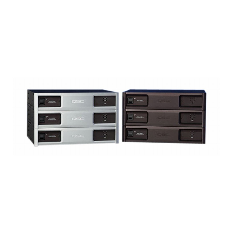
SPECIFICATIONS- Output Power: (watts per channel, stereo/parallel mode) 8 ohms, 20Hz to 20kHz, 0.03% THD 4 ohms, 20Hz to 20kHz, 0.05% THD 2 ohms, 1kHz, 1.0% THD Output Power: (watts, bridge mode) 8 ohms, 20Hz to 20kHz, 0.10% THD 4 ohms, 20Hz to 20kHz, 0.10% THD Output circuitry: Distortion (SMPTE-IM): Distortion (4 and 8 ohm, typical):... - Page 37 SPECIFICATIONS- SRA Series ALL MODELS Voltage gain: 28× (29 dB) Controls: Front- Rear- Connectors: Input- Output- Remote- DataPort- Input impedance: XLR- RCA- Indicators: Clip- Signal (-30 dB)- Power- Cooling: Amplifier Protection: Load protection: Dimensions: Width- Height- Depth- Weight: Available Finish: black chassis with black front panel/inserts or black chassis with silver front panel/inserts AC switch, Recessed Ch.
-
Page 38: Warranty Information
(USA only; other countries, see your dealer or distributor) Disclaimer QSC Audio Products, Inc. is not liable for any damage to speakers, or any other equipment that is caused by negligence or improper installation and/or use of this amplifier product. - Page 40 QSC Audio Products, Inc. 1675 MacArthur Boulevard Costa Mesa, California 92626 USA “QSC” and the QSC logo are registered with the U.S. Patent and Trademark Office. ©2002 QSC Audio Products, Inc.