Table of Contents
Advertisement
Instructions-Parts
®
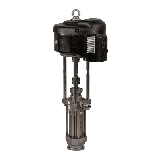
NXT
Air Motor
For use with high performance finishing and coating pumps in hazardous or
non-hazardous locations. For professional use only.
100 psi (0.7 MPa, 7.0 bar) Maximum Working Pressure
Important Safety Instructions
Read all warnings and instructions in this manual.
Save these instructions.
See page 3 for model information.
™
Models with DataTrak
include agency approvals listed below.
9902471
Class I, Div 1
Group D T3A
0359
II 1 G
Ex ia IIA T3 Ga
ITS13ATEX27862X
display
Updated technical information and repair videos are available at
www.graco.com. Click on "Tech Support", and then enter "NXT" in the
"Search by Keyword" field.
With Linear Sensor
Standard
™
With DataTrak
311238ZAM
EN
TI8621a
Advertisement
Table of Contents

Related Manuals for Graco N22DT0


Summary of Contents for Graco N22DT0
- Page 1 Group D T3A ™ With DataTrak TI8621a 0359 Updated technical information and repair videos are available at II 1 G www.graco.com. Click on “Tech Support”, and then enter “NXT” in the Ex ia IIA T3 Ga “Search by Keyword” field. ITS13ATEX27862X...
-
Page 2: Table Of Contents
Graco Standard Warranty ....48 Graco Information ......48... -
Page 3: Models
Models Models Air Motor Part No. Matrix Check your motor’s identification plate (ID) for the 6-digit part number of your motor. Use the following matrix to define the construction of your motor, based on the six digits. For exam- ple, Motor Part No. N 6 5 D T 0 represents an NXT motor (N), 6500 cc per stroke (6 5), with de-icing exhaust (D) and DataTrak monitoring (T). -
Page 4: Air Motor Part Nos
™ ™ Part No. Series Model in. (mm) De-Ice Noise Exhaust DataTrak DataTrak Sensor N22DN0 2200 6.0 (152) N22DT0 2200 6.0 (152) N22DH0 2200 6.0 (152) N22LN0 2200 6.0 (152) N22LT0 2200 6.0 (152) ... -
Page 5: Warnings
Warnings Warnings The following warnings are for the setup, use, grounding, maintenance, and repair of this equipment. The exclama- tion point symbol alerts you to a general warning and the hazard symbols refer to procedure-specific risks. Refer back to these Warnings. Additional, product-specific warnings may be found throughout the body of this manual where applicable. -
Page 6: Related Manuals
Graco replacement parts only. • Do not alter or modify equipment. • Use equipment only for its intended purpose. Call your Graco distributor for information. • Route hoses and cables away from traffic areas, sharp edges, moving parts, and hot surfaces. •... -
Page 7: Component Identification
Component Identification Component Identification Key for F Air Inlet, 3/4 npt(f) DataTrak module (see pages 9-14; not present on all Bleed-Type Master Air Valve models) Air Regulator Adjustment Knob Runaway Solenoid (component 1) Air Pressure Gauge DataTrak Sensors (component 2) Air Filter (out of view;... -
Page 8: De-Icing Control (F)
Removes harmful dirt from compressed air supply. • NXT031 with locking air regulator and 75 psi (0.51 MPa, 5.1 bar) relief valve Graco recommends using an air filter with a mini- mum measurement of 40 micron. • NXT021 with non-locking air regulator and 110 psi (0.76 MPa, 7.6 bar) relief valve. -
Page 9: Motor Lubrication
However, if any of the following criteria apply to your system, you will benefit from installing a 3/4 in. air line Graco offers airline lubricators for NXT air motors. lubricator in the air line before the air motor or from Order 214848 (1/2 in.) for NXT 2200 and NXT 3400... -
Page 10: Datatrak Controls And Indicators
DataTrak Controls and Indicators DataTrak Controls and Indicators DataTrak is included with certain models. See page 3 for a list of models featuring DataTrak. It is recommended that a 3/4 in. air line lubricator be used with DataTrak models. For remote DataTrak models, see your system operation manuals. To prevent damage to the soft key buttons, do not press the buttons with sharp objects such as pens, plastic cards, or fingernails. -
Page 11: Datatrak Operation
DataTrak Operation DataTrak Operation Run Mode DataTrak is included with certain models. See page 3 for a list of models featuring DataTrak. Runaway For remote DataTrak models, see your system operation manuals. See pages 38-39 for parts. The runaway control should be tested regularly. To test, go to Setup Mode and set value to 1 (one). - Page 12 DataTrak Operation Prime/Flush Display 1. See F . 3. To enter Prime/Flush mode, press any See F . 3. The display (Y) will turn off after 1 minute of inactivity in Run mode or 3 minutes in Setup mode. key to wake up the display, then press .
- Page 13 DataTrak Operation Table 1: Diagnostic Codes Symbol Code Code Name Diagnosis Cause Runaway Pump running faster than set runaway • Increased air pressure. limit. • Increased fluid output. • Exhausted fluid supply. Diving Up Leak during upstroke. Worn piston valve or packings. Diving Down Leak during downstroke.
-
Page 14: Replace The Datatrak Module Battery Or Fuse
4. To replace the battery, disconnect the used bat- tery and replace with an approved battery. Battery or Fuse Use only a Graco-approved replacement fuse (131a). To reduce the risk of fire and explosion, the battery and fuse must be replaced in a non-hazardous loca- Table 2: Approved Batteries tion. -
Page 15: Troubleshooting
Troubleshooting Troubleshooting Also see the troubleshooting section in the Integrated Air Control Modules manual 311239. To find parts lists for the parts identified in the troubleshooting tables, see page numbers listed in the table below. Air Motor Model Parts List Page NXT Model 2200 NXT Model 3400 NXT Model 6500... -
Page 16: Air Motor Will Not Run All Models
Troubleshooting Air Motor will not run all models Symptom Cause Check Procedure Solution Motor stuck at top or Air pressure is set below 20 Increase air pressure to 20 psi Verify air pressure is 20 psi (140 kpa, 1.4 bottom stroke of piston. psi (140 kpa, 1.4 bar). -
Page 17: Erratic Motor Operation
Troubleshooting Erratic motor operation Symptom Cause Check Procedure Solution Motor runs slow. Icing. Stop spraying for a few Reduce pressure, cycle rate, or duty cycle of Note: External icing is minutes to see if motor speed motor, and/or turn the de-icing control knob normal. -
Page 18: Erratic Air Pressure With Built In Air Control
Troubleshooting Erratic air pressure with built in air control Symptom Cause Check Procedure Solution Built in air inlet gauge Lack of air pressure. Verify air supply is present, Verify air supply is present, main air valve reads zero "0". main air valve is on, turn "C" is on, turn "C"... - Page 19 Troubleshooting Poppet Air Valve Seals Air Valve Spool Air Valve Slide Plate TI8624a Air Valve Seals Piston O-ring Poppet Piston Shaft Seals . 6. Cutaway View, Standard and DataTrak Models Poppet Linear Sensor Air Valve Seals Air Valve Spool Air Valve Slide Plate Air Valve Seals...
-
Page 20: Repair
Repair Repair Preventive Maintenance 4. Hold a metal part of the gun firmly to a grounded metal pail. Trigger the gun to relieve pressure. Schedule 5. Engage the trigger lock. The operating conditions of your particular system determine how often maintenance is required. Establish 6. - Page 21 Repair a. DataTrak Models: Remove the two screws 8. Lubricate the gaskets (46) and ensure they align (135). Carefully remove the DataTrak module with the holes at the back of the air valve (40). (131), see page 14. Disconnect the runaway Install the air valve.
- Page 22 Repair Disassemble the Air Valve 6. Carefully remove the sleeves (109). Inspect the seals (109a) and the inside surface of the sleeves and housing (103) for wear or damage. Air Valve Seal Repair Kit NXT135 is available. Parts included in the kit are marked with a symbol 7.
- Page 23 Repair 5. Lubricate o-rings (110a). Install the piston stop 7. See F . 9, page 21. Lubricate the gaskets (46) and (110) and retainer pins (111). ensure they align with the holes at the back of the air valve (40). Install the air valve. Install the screws 6.
-
Page 24: Cylinder And Piston Repair
Repair Cylinder and Piston Repair 5. Remove the outer valve cover (47). See F . 12. 6. Remove the four screws (43) and the muffler (15). Air Motor Seal Repair Kits are available. See the 7. Remove the top two air valve screws (41). Loosen parts lists on pages 32, 34, and 36 for the correct but do not remove the bottom two screws (41). - Page 25 Repair Linear Sensor Models TI8220a Apply high quality lithium grease. Torque to 30-36 ft-lb (40.6-48.8 N•m). Torque to 38-42 ft-lb (51.3-56.7 N•m). TI8219C Use 3/8 in. drive socket to fit in recess. Torque to 20 ft-lb (27.1 N•m). Fully tighten against muffler (15). Installation order: two leather o-rings (8), one u-cup (7) facing up, and one spiral ring (9).
- Page 26 20 ft-lb (27.1 N•m). 9. Reconnect the air motor to the lower (see your sep- arate pump manual). See Accessories, page 42, for a list of available adapters to connect the NXT motor to various Graco lowers. 311238ZAM...
-
Page 27: Poppet Repair
Repair Poppet Repair Poppets were upgraded in mid-2009 for improved sealing and earlier actuation. New style poppets can be used in older air motors, but do not use the back-up o-ring (12c). If you order a replacement poppet NXT100, you will automatically receive a new style poppet. -
Page 28: Replace The Linear Sensor (If Present)
Repair Replace the Linear Sensor (if 10. Thread the sensor cable through the hole (H) in the side of the adapter, and reconnect it to the circuit present) board. See F . 15, page 28. Carefully slide the housing (132) onto the air valve. Thread the screws (134) in by hand, then torque to 100 in-lb (11.3 N•m). -
Page 29: Remote Datatrak Connection Kit Nxt406
Repair Remote DataTrak Connection Kit NXT406 1. Stop the pump during the upstroke. Follow the Pressure Relief Procedure, page 20. 2. Disconnect the air line to the motor. 3. Pry off the top cover. Remove the air valve cover and discard. 4. -
Page 30: Parts
Parts Parts Air Motor Parts Drawing (Shown with DataTrak and Low Noise Exhaust) Air Motor Model Parts List Page NXT Model 2200 NXT Model 3400 NXT Model 6500 Low Noise Exhaust (24) Detail De-Ice Exhaust (22) Detail Remote Exhaust (23) Detail TI8801a Poppet (12) TI9422b... -
Page 31: Air Motor Parts Drawing (Shown With Linear Sensor)
Parts Air Motor Parts Drawing (Shown with Linear Sensor) Air Motor Model Parts List Page NXT Model 2200 NXT Model 3400 NXT Model 6500 Low Noise Exhaust (24) Detail De-Ice Exhaust (22) Detail Remote Exhaust (23) Detail TI8801a TI9422b Poppet (12) TI9421b Detail (see page 27) -
Page 32: Nxt Model 2200 Air Motors
Parts NXT Model 2200 Air Motors NXT Model 2200 Common Parts Ref. Part Description 15F639 NUT, with lockwasher; 1/2-13 Ref. Part Description NXT203 MUFFLER 15F955 COVER, top 123196 O-RING, piston; nitrile NXT204 CYLINDER 15F449 O-RING, end cap; nitrile NXT202 COVER, bottom 20... - Page 33 Parts NXT Model 2200 Varying Parts Air Motor Part Numbers Ref. Description N22DN0 N22DT0 N22DH0 N22LN0 N22LT0 N22LH0 N22RN0 N22RT0 N22RH0 KIT, de-ice exhaust, NXT110 NXT110 NXT110 includes items 20, 25, 44, 56, 57 KIT, remote exhaust; NXT105 NXT105 NXT105 includes items 20, 44 KIT, low noise exhaust;...
-
Page 34: Nxt Model 3400 Air Motors
Parts NXT Model 3400 Air Motors NXT Model 3400 Common Parts Ref. Part Description 15F639 NUT, with lockwasher; 1/2-13 Ref. Part Description NXT303 MUFFLER 15F954 COVER, top 122434 O-RING, piston; nitrile NXT304 CYLINDER 15F449 O-RING, end cap; nitrile NXT302 COVER, bottom 20... - Page 35 Parts NXT Model 3400 Varying Parts Air Motor Part Numbers N34LN0 Ref. Description N34DN0 N34DT0 N34DH0 N34LN2 N34LT0 N34LH0 N34RN0 N34RT0 N34RH0 KIT, de-ice exhaust, NXT110 NXT110 NXT110 includes items 20, 25, 44, 56, 57 KIT, remote exhaust; NXT105 NXT105 NXT105 includes items 20, 44 KIT, low noise exhaust;...
-
Page 36: Nxt Model 6500 Air Motors
Parts NXT Model 6500 Air Motors Ref. Part Description 15F639 NUT, with lockwasher; 1/2-13 NXT603 MUFFLER NXT Model 6500 Common Parts 122675 O-RING, piston; nitrile 15F448 O-RING, end cap; nitrile Ref. Part Description 20 119990 O-RING; buna-N 15F953 COVER, top 15F931 RING, lift NXT604 CYLINDER 120088 SCREW;... - Page 37 Parts NXT Model 6500 Varying Parts Air Motor Part Numbers N65LN0 Ref. Description N65DN0 N65DT0 N65DH0 N65LN2 N65LT0 N65LH0 N65RN0 N65RT0 N65RH0 257055 KIT, de-ice exhaust, NXT110 NXT110 NXT110 NXT110 includes items 20, 25, 44, 56, 57 KIT, remote exhaust; NXT105 NXT105 NXT105 includes items 20, 44 KIT, low noise exhaust;...
-
Page 38: Air Motor Parts Drawing (For Use With Remote Datatrak)
Parts Air Motor Parts Drawing (for use with Remote DataTrak) Air Motor Models N22LR0 N34LR0 N65LR0 Low Noise Exhaust (24) Detail Poppet (12) Detail TI9421b (see page 27) See Exhaust †12c Details Above TI7750b Packing Order Detail TI10948B 311238ZAM... - Page 39 Parts Air Motor Parts List (for use with Remote DataTrak) Air Motor Models N22LR0 N34LR0 N65LR0 The parts listed below are common to all NXT Model Air Motors using the remote DataTrak. Parts which vary by air motor are found in the table at the bottom of this page. Ref.
-
Page 40: Air Valve
Parts Air Valve Part NXT107 Bare Air Valve Part NXT108 Air Valve with DataTrak Module Part NXT109 Air Valve with Junction Box Detail of Part NXT109 Detail of Part NXT108 with Junction Box with DataTrak Module TI8619a TI8618a †‡106 102†‡ 20†‡... - Page 41 Parts Part NXT107 Bare Air Valve Part NXT108 Air Valve with DataTrak Module (shown) Part NXT109 Air Valve with Junction Box Housing Ref. Part Description Ref. Part Description 120279 SCREW, thread forming; #6 x 5/8 in. 20†‡ 119990 O-RING; buna-N (16 mm);...
-
Page 42: Dimensions
TI7773A Accessories Motor/Lower Adapters DataTrak Conversion Kits The following adapters are available as accessories to To convert standard NXT air motors to include DataTrak connect an NXT air motor to a Graco lower. module. Lower Adapter Air Motor Conversion Kit... -
Page 43: Mounting Hole Diagrams
Mounting Hole Diagrams Mounting Hole Diagrams NXT Model 2200 Four 3/8-16 Mounting Holes Three 5/8-11 Tie Rod Holes, 3.938 in. 5.906 in. (150 mm) x 120° Bolt Circle (100 mm) 6.750 in. (172 mm) TI8071A NXT Model 3400 Four 3/8-16 Mounting Holes 6.186 in. -
Page 44: Technical Data
Technical Data Technical Data NXT Air Motor Metric Maximum air inlet pressure 100 psi 0.7 MPa, 7.0 bar Air motor piston diameter NXT Model 6500: 10.375 in. 264 mm NXT Model 3400: 7.5 in. 191 mm NXT Model 2200: 6.0 in. 152 mm Stroke length 4.75 in. - Page 45 Technical Data Sound Data Key: 100 psi (0.7 MPa, 7 bar) 40 psi (0.3 MPa, 2.8 bar) N22DN0 Sound Power N22DN0 Sound Pressure (1 m corrected sound pressure levels based on average sound pressure readings assuming free field conditions) Cycles per Minute Cycles per Minute Key: 100 psi (0.7 MPa, 7 bar)
- Page 46 Technical Data Key: 100 psi (0.7 MPa, 7 bar) 40 psi (0.3 MPa, 2.8 bar) N34DN0 Sound Power N34DN0 Sound Pressure (1 m corrected sound pressure levels based on average sound pressure readings assuming free field conditions) Cycles per Minute Cycles per Minute Key: 100 psi (0.7 MPa, 7 bar)
- Page 47 Technical Data Key: 100 psi (0.7 MPa, 7 bar) 40 psi (0.3 MPa, 2.8 bar) N65DN0 Sound Power N65DN0 Sound Pressure (1 m corrected sound pressure levels based on average sound pressure readings assuming free field conditions) Cycles per Minute Cycles per Minute Key: 100 psi (0.7 MPa, 7 bar)
-
Page 48: Graco Standard Warranty
With the exception of any special, extended, or limited warranty published by Graco, Graco will, for a period of twelve months from the date of sale, repair or replace any part of the equipment determined by Graco to be defective.