Table of Contents
Advertisement
Quick Links
Instructions – Parts List
Parts
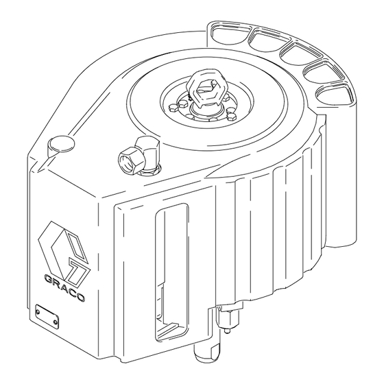
321 MM (12.625 IN.)
Premier Air Motor
100 psi (0.7 MPa, 7 bar) Maximum Air Input Pressure
Part No. 222800, Series C
Standard Motor
Part No. 240176, Series A
For use with Part No. 232095 Proportioner
United States Patent Nos. 5,189,943; Des. 345,138; 2,032,617; 5,363,739
Taiwan Patent No. 050264
Canada Patent No. D75390
Korea Patent No. 152224
Other US and Foreign Patents Pending
Read warnings and instructions.
See page 2 for Table of Contents.
GRACO INC. P.O. BOX 1441 MINNEAPOLIS, MN 55440-1441
Copyright 1993, Graco Inc. is registered to I.S. EN ISO 9001
308213M
222800 Shown
06818C
Advertisement
Chapters
Table of Contents

Related Manuals for Graco Premier 240176


Summary of Contents for Graco Premier 240176
- Page 1 Korea Patent No. 152224 Other US and Foreign Patents Pending Read warnings and instructions. See page 2 for Table of Contents. 222800 Shown 06818C GRACO INC. P.O. BOX 1441 MINNEAPOLIS, MN 55440-1441 Copyright 1993, Graco Inc. is registered to I.S. EN ISO 9001...
-
Page 2: Table Of Contents
..... . Graco Standard Warranty ..... . -
Page 3: Warnings
D This equipment is for professional use only. D Read all instruction manuals, tags, and labels before operating the equipment. D Use the equipment only for its intended purpose. If you are uncertain about usage, call your Graco distributor. D Do not alter or modify this equipment. Use only genuine Graco parts and accessories. - Page 4 Permanently coupled hoses cannot be repaired; replace the entire hose. D Use only Graco approved hoses. Do not remove the spring guard that is used to help protect the hose from rupture caused by kinks or bends near the couplings.
- Page 5 WARNING FIRE AND EXPLOSION HAZARD Improper grounding, poor ventilation, open flames or sparks can cause a hazardous condition and result in a fire or explosion and serious injury. D Ground the equipment and the object being sprayed. Refer to Grounding on page 7. D If there is any static sparking or you feel an electric shock while using this equipment, stop spray- ing immediately.
-
Page 6: Installation/Operation
The following air line accessories are available from parts drawings. Graco. Contact your Graco distributor for help in designing a system to suit your particular needs. NOTE: Always use Genuine Graco Parts and Acces- sories, available from your Graco distributor. - Page 7 Installation/Operation Grounding 2. Air and fluid hoses: use only electrically conductive hoses. WARNING 3. Air compressor: follow manufacturer’s recommen- FIRE AND EXPLOSION HAZARD dations. Before operating the pump, ground the system as explained below. Also read the section FIRE AND EXPLOSION HAZARD on page 5.
-
Page 8: Troubleshooting The Air Motor
Troubleshooting the Air Motor Preventive Maintenance Schedule Check Chart The operating conditions of your particular system NOTE: Service the air valve every 3 million cycles. If determine how often maintenance is required. Estab- the air motor stalls, service the air valve immediately. lish a preventive maintenance schedule by recording when and what kind of maintenance is needed, and then determine a regular schedule for checking your... -
Page 9: Service
Service Pressure Relief Procedure Required Service Tools D Phillips screwdriver WARNING INJECTION HAZARD D Flat blade screwdriver The system pressure must be manually relieved to prevent the system from starting or spraying accidentally. Fluid D 16 mm box wrench under high pressure can be injected through the skin and cause serious injury. -
Page 10: Air Motor Shroud
Service Air Valve Replacement WARNING NOTE: Service the air valve every 3 million cycles. If To avoid serious injury and equipment the air motor stalls, service the air valve immediately. damage, do not lift the equipment by the Premier air motor lift ring if the total weight of the equipment exceeds 550 lb To replace the entire air valve assembly, order Part (250 kg). -
Page 11: These Parts Are Included In Air Valve Repair Kit
Service 222800 Shown Torque to 22–23 NSm (195–205 in-lb) Apply sealant. Grease ends of trip rod. { These parts are included in Air Valve Repair Kit 222959, which may be purchased separately. Detail of Slide Plate Seals Grease the grooves of the slide plates (G). -
Page 12: Air Valve Service
Service Air Valve Service 2. Remove the air motor shroud as described under Air Motor Shroud Disassembly, on page 10. NOTE: Service the air valve every 3 million cycles. If the air motor stalls, service the air valve immediately. 3. Follow steps 3 and 4 under Air Valve Replace- ment on page 10. - Page 13 Service 8. With your fingers, snap the slide blocks (119) off of a. Place the flats of one trip rod (106) in a vise the valve carriage (111) to free the o-rings (120). with soft jaws and unscrew the other trip rod Clean and inspect the slide blocks.
- Page 14 Service 5. Install the bearings (107}) on the valve carriage 9. Insert the detent assemblies into the valve carriage (111). Apply thread sealant and torque the screws (111) so the detent rollers (115) face out of the (104) to 2–3 NSm (20–30 in-lb). carriage.
- Page 15 Service WARNING MOVING PARTS HAZARD Use caution when disassembling the trip rod. The trip rod spring (110) is under tension. When the trip rod is unscrewed tension is released, and parts may be projected through the air with considerable force. 106} 108} 129}...
-
Page 16: Subplate And Rocker Assemblies
Service Subplate and Rocker Assemblies 10. Remove the two screws (42), the top rod fitting (20), and the push rod (19) from the motor cap (2). NOTE: Air Valve Repair Kit 222959 is available. Parts Using an o-ring pick, pull out the seal (21). Inspect included in the kit are marked with a symbol ({). - Page 17 Service 222800 Shown { These parts are included in Air Valve Repair Kit 222959, which may be purchased separately. Lubricate. Apply sealant. Torque to 22–23 NSm (195–205 in-lb). Torque to 10–12 NSm (90–110 in-lb). Torque to 2–3 NSm (20–30 in-lb). Torque to 24–27 NSm (18–20 ft-lb).
-
Page 18: Piston And Piston Rod Seals
Service Piston and Piston Rod Seals 11. Check the inner surface of the cylinder (1) for scoring or other damage. NOTE: Air Motor Repair Kit 222958 is available. Parts included in the kit are marked with an asterisk (*). For Reassembly the best results, use all the parts in the kit. -
Page 19: Torque To 24-27 Nsm (18-20 Ft-Lb)
Service 222800 Shown Lubricate. Apply sealant. Notch faces down, out of bearing (6). Torque to 6–7 NSm (55–65 in-lb). Torque to 39–43 NSm (29–32 ft-lb). Lips must face up, toward cylinder (1). Lubricate inside diameter with rag soaked in grease. Torque to 203–228 NSm (150–170 ft-lb). - Page 20 Notes 308213...
- Page 21 Parts Model 222800 Premier Air Motor, Series C Ref. Part No. Description Qty. (shown) 184353 RING, lift Model 240176 Premier Air Motor, Series A 109484 O-RING; buna-N NOTE: Some parts of this assembly are listed and 107558 SCREW, cap, hex hd; M8 x 1.25; pictured on page 22.
- Page 22 Parts NOTE: Some parts of this assembly are listed and pictured on page 21. 27{n 26{n 01345A 308213...
- Page 23 Parts Model 222800 Premier Air Motor, Series C (shown) Model 240176 Premier Air Motor, Series A NOTE: Some parts of this assembly are listed and pictured on page 21. Ref. Ref. Part No. Description Qty. Part No. Description Qty. 184373 CYLINDER, motor 184607 SLEEVE, rocker arm...
- Page 24 Parts Part No. 222799 Air Valve, Series A 106} 108} 129} 103{} 102{} 110} 129} 127Y 108} {120 109} 107} 106} 102{} 103{} 01346 308213...
- Page 25 Parts Part No. 222799 Air Valve, Series A Ref. Ref. Part No. Description Qty. Part No. Description Qty. 184375 HOUSING, valve 121n 109513 ROLLER, bearing 102{} 109494 SEAL, rod; polyurethane 276068 RETAINER, bearing 103{} 276067 FITTING, rod; acetal 123n 184605 PIN, roller 107100 SCREW, cap, socket hd;...
-
Page 26: Air Motor
Technical Data Category Data Maximum air input pressure 0.7 MPa, 7 bar (100 psi) Operating pressure range .07–0.7 MPa, 0.7–7 bar (10–100 psi) Maximum recommended speed 50 cycles per min Operating temperature 12.8 to 65.6_C (55 to 150_F) Air motor piston effective area 800 cm (124 in. -
Page 27: Dimensions
Dimensions 455 mm Top View (17.9 in.) 585 mm (23.0 in.) 06554 1” npsm(f) Air Inlet 438.4 mm 424.5 mm (17.3 in.) Side View (16.7 in.) 38.3 mm (1.5 in.) 158.8 mm Upstroke (6.25 in.) Downstroke 06553 135.0 mm 67.5 mm (5.3 in.) (2.7 in.) 116.9 mm... -
Page 28: Graco Standard Warranty
Graco distributor to the original purchaser for use. With the exception of any special, extended, or limited warranty published by Graco, Graco will, for a period of twelve months from the date of sale, repair or replace any part of the equipment determined by Graco to be defective.