Table of Contents
Advertisement
Quick Links
Download this manual
See also:
Instruction Manual
5001571
Your new tool has been engineered and manufactured to WEN's highest standards for dependability,
ease of operation, and operator safety. When properly cared for, this product will supply you years
of rugged, trouble-free performance. Pay close attention to the rules for safe operation, warnings,
and cautions. If you use your tool properly and for intended purpose, you will enjoy years of safe,
reliable service.
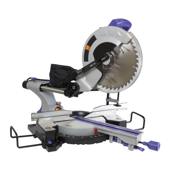
12˝ SINGLE BEVEL
SLIDING COMPOUND
IMPORTANT:
NEED HELP? CONTACT US!
Have product questions? Need technical support?
Please feel free to contact us at:
800-232-1195
techsupport@wenproducts.com
WENPRODUCTS.COM
MITER SAW
Model # 70712
bit.ly/wenvideo
(M-F 8AM-5PM CST)
Advertisement
Table of Contents

Related Manuals for Wen 70712


Summary of Contents for Wen 70712
- Page 1 5001571 IMPORTANT: Your new tool has been engineered and manufactured to WEN’s highest standards for dependability, ease of operation, and operator safety. When properly cared for, this product will supply you years of rugged, trouble-free performance. Pay close attention to the rules for safe operation, warnings, and cautions.
- Page 2 Specific Safety Rules For Miter Saws Electrical Information Know Your Miter Saw Assembly and Adjustments Operation Maintenance Exploded View & Parts List Warranty TECHNICAL DATA 70712 Model Number: 120 V, 60 Hz, 15A Motor: 5000 RPM No Load Speed: 12˝ Blade Size: Arbor Size: 1˝...
-
Page 3: General Safety Rules
GENERAL SAFETY RULES Safety is a combination of common sense, staying alert and knowing how your item works. SAVE THESE SAFETY INSTRUCTIONS. WARNING! Read all safety warnings and all instructions. Failure to follow the warnings and instruc- tions may result in electric shock, fire and serious injury. To avoid mistakes and serious injury, do not plug in your tool until the following steps have been read and understood. - Page 4 GENERAL SAFETY RULES POWER TOOL USE AND CARE 1. Avoid accidental start-ups. Make sure the power switch is in the OFF position before connecting the plug to a power source or carrying the tool. 2. Check power tool for damaged parts. Check for misalignment of moving parts, jamming, breakage, improper mounting, or any other conditions that may affect the tool’s operation.
- Page 5 SPECIFIC RULES FOR THE MITER SAW 4. Use dust masks or other respiratory protection during operation and cleaning. Sawdust is harmful to your health. 5. Keep hands away from cutting area. Never use your hands to remove sawdust, chips or workpiece near the saw blade or the cutting path of the saw.
-
Page 6: Electrical Information
ELECTRICAL INFORMATION DOUBLE INSULATION Double insulation is a concept in safety in electric power tools, which eliminates the need for the usual three-wire grounded power cord. All exposed metal parts are isolated from the internal metal motor components with protect- ing insulation. -
Page 7: Know Your Band Saw
KNOW YOUR BAND SAW Operating Handle Miter Scale ON/OFF Switch Bevel Lock Knob Blade Guard Slide Bar Fence Slide Lock Knob Miter Table Dust Extraction Port Table Insert Guard Retraction Arm Miter Table Lock UNPACKING If you find any pieces that are missing or wrong, do not operate the tool until the parts have been replaced. Failure to do so could result in serious personal injury. -
Page 8: Assembly And Adjustments
ASSEMBLY AND ADJUSTMENTS TRANSPORTATION Only lift the miter saw after switching off the saw, locking down the saw arm, and unplugging the machine from its power source. Only lift the saw by the carrying handle located on top of the motor or by the saw base. Do not lift the saw using the guard or the operating handle. -
Page 9: Spindle Lock Button
ASSEMBLY AND ADJUSTMENTS BEVEL LOCK The bevel lock is used to set the blade at the desired bevel angle (FIGURE 5). The miter saw bevels from 0° to 45° left only. Hold the operating handle and loosen the bevel lock to set the bevel angle. Tighten the bevel lock. WARNING: Be sure to tighten the bevel lock before making a cut. - Page 10 ASSEMBLY AND ADJUSTMENTS TURNING ON/OFF 1. Pull the ON/OFF trigger switch found inside the front handle to start the miter saw. 2. To turn the saw off, release the ON/OFF trigger switch. SETTING THE BLADE SQUARE WITH THE TABLE 1. Make sure that the power cord is removed from the power source. FIGURE 10 2.
-
Page 11: Changing A Blade
ASSEMBLY AND ADJUSTMENTS SETTING THE FENCE SQUARE WITH THE TABLE 1. Make sure that the power cord is removed from the power source. 2. Push the saw arm down to it lowest position and engage the release knob (FIGURE 2) to hold the saw arm in the lowest position. 3. - Page 12 ASSEMBLY AND ADJUSTMENTS 7. Hold the rotating guard up and press the spindle lock button (FIGURE 7). Rotate the blade until the spindle engages to lock the blade. 8. Turn the hex key clockwise to loosen the arbor bolt and remove it (FIGURE 20). 9.
-
Page 13: Bevel Cut
OPERATION 5. Place the workpiece flat on the table with one edge securely against the fence. If the board is warped, place the convex side against the fence. If the concave side is placed against the fence, the board could break and jam the blade. 6. -
Page 14: Compound Miter Cut
OPERATION WARNING: Be sure to tighten the miter lock before making a cut. Failure to do so could result in the table moving during operation, causing serious personal injury. 5. Loosen the bevel lock (FIGURE 11). Move the saw arm to the desired bevel angle (between 0º... - Page 15 OPERATION 6. When cutting long pieces of timber, support the opposite end of the timber with the sidebars, a roller stand or a work surface that is level with the saw table. 7. Use the clamp assembly to secure the workpiece wherever possible. 8.
- Page 16 EXPLODED VIEW & PARTS LIST...
- Page 17 EXPLODED VIEW & PARTS LIST Part No. Description Part No. Description 70712C-001 Bolt M8X25 70712B-038 Small Knob M5X33 70712B-002 Hex Nut M8, 3.2mm 70712B-039 Rubber Foot 70712B-003 Slide Lock Knob 70712B-040 Locking Bar Pull Rod Locking 70712B-041 Seal Ring φ6.3Xφ1.8 70712B-004 Pressure Spring Trigger Spring...
- Page 18 EXPLODED VIEW & PARTS LIST Part No. Description Part No. Description 70712B-075 Bearing Cover 70712B-099 Brush Hold 70712B-076 Washer 70712B-100 Washer 10 70712B-077 Bolt M5X10 70712B-101 Spring Washer 10 70712B-078 Output Shaft 70712B-102 Bolt M6X70 70712B-079 Half Round Key 70712B-103 Bolt ST6.3X25 70712B-080 Inner Flange...
- Page 19 LIMITED ONE YEAR WARRANTY WEN Products is committed to build tools that are dependable for years. Our warranties are consistent with this commitment and our dedication to quality. LIMITED WARRANTY OF WEN CONSUMER POWER TOOLS PRODUCTS FOR HOME USE GREAT LAKES TECHNOLOGIES, LLC (“Seller”) warrants to the original purchaser only, that all WEN con- sumer power tools will be free from defects in material or workmanship for a period of one (1) year from date of purchase.
- Page 20 Thanks for remembering...