Advertisement
Model No. 831.21641.0
Serial No.
Serial Number
• Assembly
• Operation
• Maintenance
• Part List and Drawing
CAUTION
Read all precautions and instruc-
tions in this manual before using
this equipment. Keep this manual
for future reference.
Decal
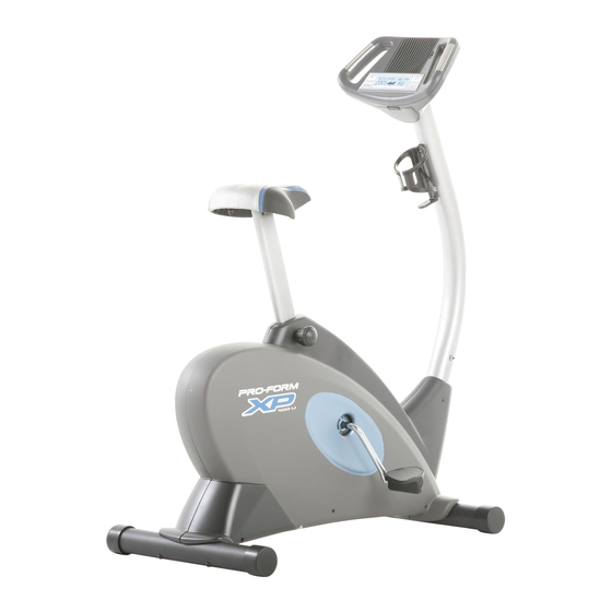
BIKE EXERCISER
User's Manual
Sears, Roebuck and Co., Hoffman Estates, IL 60179
Advertisement
Table of Contents

Related Manuals for ProForm XP 100 U 831.21641.0


Summary of Contents for ProForm XP 100 U 831.21641.0
- Page 1 Model No. 831.21641.0 Serial No. Serial Number Decal • Assembly • Operation • Maintenance • Part List and Drawing CAUTION Read all precautions and instruc- tions in this manual before using this equipment. Keep this manual for future reference. BIKE EXERCISER User’s Manual Sears, Roebuck and Co., Hoffman Estates, IL 60179...
-
Page 2: Table Of Contents
TABLE OF CONTENTS IMPORTANT PRECAUTIONS ..............2 BEFORE YOU BEGIN . -
Page 3: Before You Begin
BEFORE YOU BEGIN Congratulations for selecting the new PROFORM 100 U exercise cycle. Cycling is one of the most effective exercises for increasing cardiovascular fit- ness, building endurance, and toning the entire body. The XP 100 U exercise cycle offers a selection of fea- tures designed to let you enjoy this healthful exercise in the convenience and privacy of your home. -
Page 4: Assembly
ASSEMBLY Assembly requires two persons. Place all parts of the exercise cycle in a cleared area and remove the packing materials. Do not dispose of the packing materials until assembly is completed. Assembly requires the included tools and your own adjustable wrench driver Use the part drawings below to identify the small parts used in assembly. - Page 5 2. While another person lifts the rear of the Frame (1), attach the Rear Stabilizer (14) to the Frame with two M10 x 74mm Button Screws (33). 3. While another person holds the Upright (3) near the Frame (1), connect the Upper Wire Harness (32) to the Lower Wire Harness (31).
- Page 6 5. The Console (6) requires four “D” batteries (not included); alkaline batteries are recommended. IMPORTANT: If the exercise cycle has been exposed to cold temperatures, allow it to warm to room temperature before inserting batteries into the Console. If you do not do this, the console dis- plays or other electronic components may become damaged.
- Page 7 8. Remove the packing tube from the Frame (1), and dis- card the packing tube. Turn the Seat Knob (11) counterclockwise two or three turns to loosen it (if the Seat Knob is not loosened enough, it may scratch the Seat Post [5]). Next, pull the Seat Knob, insert the Seat Post into the Frame (1), and then release the Seat Knob.
-
Page 8: How To Operate The Exercise Cycle
HOW TO OPERATE THE EXERCISE CYCLE HOW TO ADJUST THE SEAT For effective exer- cise, the seat should be at the proper height. As you pedal, there should be a slight Seat bend in your knees Post when the pedals are in the lowest position. - Page 9 FEATURES OF THE CONSOLE The advanced console offers an array of features designed to make your workouts more effective and enjoyable. When you select the manual mode of the console, you can change the resistance of the pedals with the touch of a button.
- Page 10 HOW TO USE THE MANUAL MODE Press any button or begin pedaling to turn on the console. A moment after you turn on the console, the dis- play will light. Select the manual mode. Each time you turn on the console, the manual mode will be selected automatically.
- Page 11 Measure your heart rate if desired. If there are sheets of clear plastic on the metal contacts on the handgrip pulse sensor, remove the plastic. To measure your heart rate, hold the handgrip pulse sen- sor with your palms resting against the metal contacts. Avoid moving your hands or gripping the contacts too tightly.
- Page 12 HOW TO USE A TRAINER PROGRAM Press any button or begin pedaling to turn on the console. A moment after you turn on the console, the dis- play will light. Select a trainer program. Press the Program button repeatedly until the words TRAINER 1 or TRAINER 2 appear in the display.
- Page 13 HOW TO USE A CROSS TRAINING PROGRAM Press any button or begin pedaling to turn on the console. A moment after you turn on the console, the dis- play will light. Select a cross training program. Press the Program button repeatedly until the name of the desired cross training program appears in the display.
- Page 14 Continue the cross training program. When you have performed the recommended number of repetitions, the words START PEDAL- ING will appear in the display. To continue the cross training program, step onto the exercise cycle and start pedaling. The pedals will automati- cally adjust to the resistance setting for the next segment.
- Page 15 HOW TO USE A CALORIE GOAL PROGRAM Press any button or begin pedaling to turn on the console. A moment after you turn on the console, the dis- play will light. Select one of the calorie goal programs. Press the Program button repeatedly until the name of the desired calorie goal program appears in the display.
-
Page 16: Maintenance And Troubleshooting
MAINTENANCE AND TROUBLESHOOTING Inspect and properly tighten all parts of the exercise cycle regularly. Replace any worn parts immediately. To clean the exercise cycle, use a damp cloth and a small amount of mild soap—never use alcohol, abrasives, or chemicals to clean the exercise cycle. -
Page 17: Conditioning Guidelines
CONDITIONING GUIDELINES The following guidelines will help you to plan your exercise program. Remember that proper nutrition and adequate rest are essential for successful results. WARNING: Before beginning this or any exercise pro- gram, consult your physician. This is espe- cially important for persons over the age of 35 or persons with pre-existing health prob- lems. -
Page 18: Part List
PART LIST—Model No. 831.21641.0 Key No. Qty. Description Frame Front Stabilizer Upright Endcap Seat Post Console Eddy Mechanism Resistance Motor Crank Nut Pillow Block Adjustment Knob Seat Pulley/Crank Rear Stabilizer M4 x 22mm Screw Magnet Left Side Shield Right Side Shield Eddy Axle Assembly Seat Post Bushing Reed Switch/Wire... -
Page 19: Exploded Drawing
EXPLODED DRAWING—Model No. 831.21641.0 R0307A... -
Page 20: 90 Day Full Warranty
Get it fixed, at your home or ours! For repair—in your home—of all major brand appliances, lawn and garden equipment, or heating and cooling systems, no matter who made it, no matter who sold it! For the replacement parts, accessories, and user’s manuals that you need to do-it-yourself. For Sears professional installation of home appliances and items like garage door openers and water heaters.