Table of Contents
Advertisement
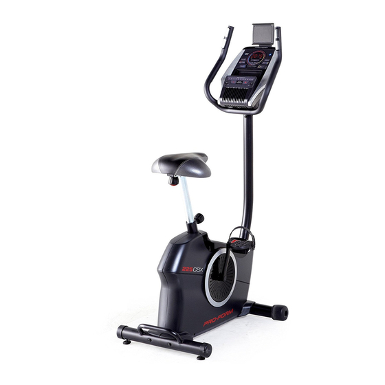
Model No. PFEVEX74016.0
Serial No.
USER'S MANUAL
Write the serial number in the space
above for reference.
Serial Number
Decal
CUSTOMER SERVICE
UNITED KINGDOM
Call: 0330 123 1045
From Ireland: 053 92 36102
Website: www.iconsupport.eu
E-mail: csuk@iconeurope.com
Write:
ICON Health & Fitness, Ltd.
Unit 1D, The Gateway
Fryers Way, Silkwood Park
OSSETT
WF5 9TJ
UNITED KINGDOM
AUSTRALIA
Call: 1800 993 770
E-mail: australiacc@iconfitness.com
Write:
ICON Health & Fitness
PO Box 635
WINSTON HILLS NSW 2153
AUSTRALIA
CAUTION
Read all precautions and
instructions in this manual before
using this equipment. Keep this
manual for future reference.
www.iconeurope.com
Advertisement
Table of Contents

Related Manuals for ProForm 225 CSX


Summary of Contents for ProForm 225 CSX
- Page 1 Model No. PFEVEX74016.0 Serial No. USER’S MANUAL Write the serial number in the space above for reference. Serial Number Decal CUSTOMER SERVICE UNITED KINGDOM Call: 0330 123 1045 From Ireland: 053 92 36102 Website: www.iconsupport.eu E-mail: csuk@iconeurope.com Write: ICON Health & Fitness, Ltd. Unit 1D, The Gateway Fryers Way, Silkwood Park OSSETT...
-
Page 2: Table Of Contents
PROFORM is a registered trademark of ICON Health & Fitness, Inc. IFIT is a registered trademark of ICON Health & Fitness, Inc. App Store is a trademark of Apple Inc., registered in the U.S. and other countries. Android and Google Play are trademarks of Google Inc. -
Page 3: Important Precautions
IMPORTANT PRECAUTIONS WARNING: To reduce the risk of serious injury, read all important precautions and instructions in this manual and all warnings on your exercise bike before using your exercise bike. ICON assumes no responsibility for personal injury or property damage sustained by or through the use of this product. -
Page 4: Before You Begin
The ance, and toning the body. The 225 CSX exercise bike model number and the location of the serial number provides an impressive selection of features designed decal are shown on the front cover of this manual. -
Page 5: Part Identification Chart
PART IDENTIFICATION CHART Use the drawings below to identify the small parts needed for assembly. The number in parentheses below each drawing is the key number of the part, from the PART LIST near the end of this manual. The number following the key number is the quantity needed for assembly. -
Page 6: Assembly
ASSEMBLY • Assembly requires two persons. • In addition to the included tool(s), assembly requires the following tools: • Place all parts in a cleared area and remove the one Phillips screwdriver packing materials. Do not dispose of the packing materials until you finish all assembly steps. - Page 7 2. Using a standard screwdriver, remove the Shield Cover (26) from the Left and Right Shields (37, 58). If there is a shipping tube (not shown) on the rear of the Frame (50), remove the screws from the shipping tube and discard the screws and the shipping tube.
- Page 8 4. Set the Seat Carriage (15) on the Seat Post (18) and hold it in place. Insert the Seat Knob (19) upward into the Seat Post (18), and tighten the Seat Knob into the Seat Bracket (14) inside the Seat Carriage (15). 5.
- Page 9 6. Tip: Avoid pinching the Main Wire (25). Orient the Upright (27) as shown, and hold it on the Frame (50). Attach the Upright (27) with four M8 x 20mm Avoid pinching the Screws (29); start all the Screws, and then Main Wire (25) tighten them.
- Page 10 8. Orient the Shield Cover (26) as shown, and press it onto the Left and Right Shields (37, 58). 37, 58 9. Orient the Console Cover (3) as shown, and slide it onto the Upright (27). Tip: Avoid pinching the Main Wire (25). Insert the Handlebar (4) into the Upright (27).
- Page 11 10. Untie and discard the wire tie on the Main Wire (25). Route the Main Wire upward through the Handlebar (4) as shown. While a second person holds the Console (7) near the Handlebar (4), connect the wires (H) on the Console to the Main Wire (25) and the Pulse Wire (23).
- Page 12 13. Attach the Tablet Holder (1) to the Console (7) with four #8 x 5/8" Screws (8); start all the Screws, and then tighten them. 14. Identify the Right Pedal (60). Using an adjustable wrench, firmly tighten the Right Pedal (60) clockwise into the Right Crank Arm (59).
- Page 13 15. Plug the Power Adapter (30) into the receptacle on the frame of the exercise bike. Note: To plug the Power Adapter (30) into an outlet, see HOW TO PLUG IN THE POWER ADAPTER on page 14. 16. After the exercise bike is assembled, inspect it to make sure that it is assembled correctly and that it functions properly.
-
Page 14: How To Use The Exercise Bike
HOW TO USE THE EXERCISE BIKE HOW TO PLUG IN THE POWER ADAPTER HOW TO ADJUST THE HEIGHT OF THE SEAT IMPORTANT: If the exercise bike has been exposed For effective exercise, the seat should be at the proper to cold temperatures, allow it to warm to room height. - Page 15 HOW TO ADJUST THE PEDAL STRAPS HOW TO USE THE TABLET HOLDER To adjust the IMPORTANT: The tablet holder is designed for use with most full-size tablets. Do not place any other pedal straps, first electronic device or object in the tablet holder. pull the ends of the straps off the tabs on the ped-...
- Page 16 CONSOLE DIAGRAM When you use the manual mode of the console, you can change the resistance of the pedals with the touch of a button. You can also create custom manual workouts with alternating high- and low-intensity intervals. As you exercise, the console will provide continu- ous exercise feedback.
- Page 17 HOW TO USE THE MANUAL MODE Note: After you press a button, it will take a moment for the pedals to reach the selected 1. Turn on the console. resistance level. 5. Do interval training, if desired. Begin pedaling or press any button on the console to turn on the console.
- Page 18 To set a power output target, press the Watts/ 7. Follow your progress with the display. Kg increase and decrease buttons until the desired power output target appears in the display. The display can show the following workout information: Note: After you set a power output target, the resistance level will automatically adjust to a preset Calories (CALS)—The approximate number of level.
- Page 19 Change the volume level of the When your pulse is detected, your heart rate will be console by pressing the Vol shown in the display. For the most accurate heart increase and decrease buttons. rate reading, hold the contacts for at least 15 seconds.
- Page 20 HOW TO USE AN ONBOARD WORKOUT At the end of each segment of the workout, a series of tones will sound. The resistance level 1. Turn on the console. for the next segment will appear in the display for a few seconds to alert you. The resistance of the Begin pedaling or press any button on the console pedals will then change.
- Page 21 5. Follow your progress with the display. THE OPTIONAL CHEST HEART RATE MONITOR See step 7 on page 18. Whether your goal is to 6. Measure your heart rate if desired. burn fat or to strengthen your See step 8 on page 19. cardiovascular system, the key 7.
- Page 22 2. Connect your smart device to the console. console for 5 seconds; the LED on the console will light while the button is held and turn off when the button is Follow the instructions in the iFit app to connect released.
-
Page 23: Maintenance And Troubleshooting
MAINTENANCE AND TROUBLESHOOTING MAINTENANCE Locate the Reed Switch (64). Slightly loosen the M4 x 19mm Screw (65). Regular maintenance is important for optimal performance and to reduce wear. Inspect and properly tighten all parts each time the exercise bike is used. Replace any worn parts immediately. - Page 24 HOW TO ADJUST THE DRIVE BELT Using an M10 socket wrench with an extension (not included), reach into the opening in the bottom of the If you can feel the pedals slip while you are pedaling, Right Shield (58) and tighten the M10 x 50mm Screw even when the resistance is adjusted to the highest (49) a few turns until the Drive Belt (not shown) is tight;...
-
Page 25: Exercise Guidelines
EXERCISE GUIDELINES Burning Fat—To burn fat effectively, you must exer- WARNING: cise at a low intensity level for a sustained period of Before beginning this time. During the first few minutes of exercise, your or any exercise program, consult your physi- body uses carbohydrate calories for energy. -
Page 26: Part List
PART LIST Model No. PFEVEX74016.0 R0416A Key No. Qty. Description Key No. Qty. Description Tablet Holder Left Crank Arm M4 x 16mm Screw M4 x 19mm Self-tapping Screw Console Cover Left Shield Handlebar Snap Ring Handlebar Cap Bearing Pulse Sensor M4 x 12mm Screw Console Resistance Cable... -
Page 27: Exploded Drawing
EXPLODED DRAWING Model No. PFEVEX74016.0 R0416A... -
Page 28: Ordering Replacement Parts
ORDERING REPLACEMENT PARTS To order replacement parts, please see the front cover of this manual. To help us assist you, be prepared to provide the following information when contacting us: • the model number and serial number of the product (see the front cover of this manual) •...