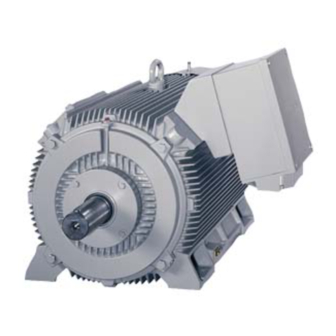
Siemens 1LA8 Operating Instructions Manual
Simotics tn series n-compact
induction motor
Hide thumbs
Also See for 1LA8:
- Operating instructions manual (148 pages) ,
- Operating & installation instructions manual (160 pages) ,
- Operating instructions manual (30 pages)

Related Manuals for Siemens 1LA8


Summary of Contents for Siemens 1LA8
- Page 1 For employment in zone 22 (IEC/EN 60079-10-2) II 3D Ex tc IIIB T125°C Dc SIMOTICS TN Series N-compact Induction motor Type 1LA8 Operating Instructions Edition 05/2014 Answers for industry.
- Page 2 23.05.2014 10:18 V8.00...
- Page 3 Introduction Safety information Description Induction motor Preparations for use SIMOTICS TN Series N-compact 1LA8 Assembly Electrical connection Operating Instructions Start-up Operation Maintenance Spare parts Disposal Service and Support For employment in zone 22 (IEC/EN 60079-10-2) Technical data II 3D Ex tc IIIB T125°C Dc...
-
Page 4: Edition
Note the following: WARNING Siemens products may only be used for the applications described in the catalog and in the relevant technical documentation. If products and components from other manufacturers are used, these must be recommended or approved by Siemens. Proper transport, storage, installation, assembly, commissioning, operation and maintenance are required to ensure that the products operate safely and without any problems. - Page 5 Torsional loading of the drive train due to faults in the electrical supply........32 4.11 Transport and storage.........................32 4.11.1 Checking the delivery........................33 4.11.2 Requirements for safe lifting and transporting................33 4.11.3 Rotor shipping brace........................34 4.11.4 Transporting the machine set......................35 4.11.5 Storage............................36 4.11.6 Protection against corrosion......................39 SIMOTICS TN Series N-compact 1LA8 Operating Instructions 05/2014...
- Page 6 Bringing cables into the terminal box 1XB16.. and routing them with gable gland.....69 6.4.2 Bringing cables into the terminal box 1XB.. and routing them with onion sealing ring....70 6.4.3 Connecting cables with cable lugs....................71 6.4.4 Connection without cable lugs.....................72 SIMOTICS TN Series N-compact 1LA8 Operating Instructions 05/2014...
- Page 7 Avoidance of damage to roller bearings during stoppages............94 8.8.3 Shaft grounding brushes (optional).....................95 8.8.4 Measurement of the insulation resistance after an extended stoppage........95 Decommissioning the machine....................96 8.10 Re-commissioning the machine....................96 8.11 faults............................96 8.11.1 Inspections in the event of faults....................96 SIMOTICS TN Series N-compact 1LA8 Operating Instructions 05/2014...
- Page 8 Drive end rolling-contact bearings without bearing housing............130 10.7 Roller bearings, DE - end shield with integrated bearing cover..........131 10.8 Non-drive end rolling-contact bearings with bearing housing............132 10.9 Non-drive end rolling-contact bearings without bearing housing..........133 SIMOTICS TN Series N-compact 1LA8 Operating Instructions 05/2014...
- Page 9 Cable entry plate versions......................69 Table 6-5 Terminal boxes with onion sealing ring..................70 Table 6-6 Minimum air clearance dependent on rms value of the alternating voltage U ......76 Table 6-7 Maximum converter peak voltage....................80 SIMOTICS TN Series N-compact 1LA8 Operating Instructions 05/2014...
- Page 10 Schematic diagram of the water drain holes................54 Figure 5-3 Schematic diagram: Aligning the machine to the driven machine..........57 Figure 6-1 Terminal box 1XB1621........................62 Figure 6-2 Terminal box 1XB1631........................63 Figure 6-3 Terminal box 1XB1634 .......................64 SIMOTICS TN Series N-compact 1LA8 Operating Instructions 05/2014...
- Page 11 Figure 10-9 Two-part cable entry........................135 Figure 10-10 Terminal box 1XB1631 with standard cable entry..............137 Figure 10-11 Two-part cable entry........................137 Figure 10-12 Terminal box 1XB1634 with standard cable entry..............139 Figure 10-13 Two-pane cable entry........................139 SIMOTICS TN Series N-compact 1LA8 Operating Instructions 05/2014...
- Page 12 Table of contents SIMOTICS TN Series N-compact 1LA8 Operating Instructions 05/2014...
-
Page 13: Disposal
– Lists on the second level are hyphenated. Note A Note is an important item of information about the product, handling of the product or the relevant section of the document. Notes provide you with help or further suggestions/ideas. SIMOTICS TN Series N-compact 1LA8 Operating Instructions 05/2014... - Page 14 Introduction 1.1 About these instructions SIMOTICS TN Series N-compact 1LA8 Operating Instructions 05/2014...
-
Page 15: Safety Information
An explosion can result. This can result in death, serious injury or material damage. Commission the machine only when the plant conformance with the explosion protection directive has been confirmed. SIMOTICS TN Series N-compact 1LA8 Operating Instructions 05/2014... -
Page 16: The Five Safety Rules
● General safety regulations applicable in the country where the machine is deployed. ● Manufacturer-specific and application-specific regulations ● Special agreements made with the operator ● Separate safety instructions supplied with the machine ● Safety symbols and instructions on the machine and its packaging SIMOTICS TN Series N-compact 1LA8 Operating Instructions 05/2014... - Page 17 Poisoning, skin damage, cauterization of the respiratory tract, and other health damage may result. ● Read the information in these operating instructions and the product information supplied by the manufacturer. ● Observe the relevant safety regulations and wear the personal protective equipment specified. SIMOTICS TN Series N-compact 1LA8 Operating Instructions 05/2014...
-
Page 18: For Use In Hazardous Zone 2 Or Zone 22
The basic requirements relating to the assessment of ignition hazards arising from electrical equipment and their operation in hazardous zones are specified, for instance, in 94/9/EC and 1999/92/EC directives as well as in the IEC / EN 60079 series of standards. SIMOTICS TN Series N-compact 1LA8 Operating Instructions 05/2014... -
Page 19: Electrostatic Sensitive Devices
(1) Sitting (2) Standing (3) Standing/sitting a = conductive floor surface b = ESD table c = ESD shoes d = ESD overall e = ESD wristband f = cabinet ground connection SIMOTICS TN Series N-compact 1LA8 Operating Instructions 05/2014... -
Page 20: Electromagnetic Compatibility
A strongly irregular torque, for example with the drive of a reciprocating motor, forces a non- sinusoidal motor current. The emerging harmonics can have an impermissible influence on the line power supply via the connection lines. SIMOTICS TN Series N-compact 1LA8 Operating Instructions 05/2014... -
Page 21: Interference Voltages When Operating The Converter
● Protect the personnel working in the plant by taking appropriate measures, such as erecting identifying markings, safety barriers and warning signs and giving safety talks. ● Observe the nationally applicable health and safety regulations. ● Do not carry any magnetic or electronic data media. SIMOTICS TN Series N-compact 1LA8 Operating Instructions 05/2014... - Page 22 Safety information 2.11 Electromagnetic fields when operating electrical power engineering installations SIMOTICS TN Series N-compact 1LA8 Operating Instructions 05/2014...
-
Page 23: Description
Never operate this machine in the above mentioned areas. Machine design The regulations and standards used as the basis to design and test this machine are stamped on the rating plate. SIMOTICS TN Series N-compact 1LA8 Operating Instructions 05/2014... - Page 24 ① Rating plate The rating plate shows the identification data and the most important technical data. The data on the rating plate and the contractual agreements define the limits of proper usage. SIMOTICS TN Series N-compact 1LA8 Operating Instructions 05/2014...
- Page 25 The rotor assembly is pressed onto the shaft together with the cage winding. The drive end of the shaft usually has a cylindrical shaft end. Dependent on the design, a second shaft end may be located at the non-drive end. SIMOTICS TN Series N-compact 1LA8 Operating Instructions 05/2014...
- Page 26 ● Drive end: Pairing of angular-contact ball bearing / deep-groove shaft height 355 ... 450 ball bearing as a fixed bearing ● Non-drive end: Deep-groove ball bearing as a floating bearing with axial compression springs SIMOTICS TN Series N-compact 1LA8 Operating Instructions 05/2014...
- Page 27 Depending on the version, the terminal box can be rotated. It can then be rotated through increments of 90° corresponding to the connection direction. If required, contact your Service Center (Page 143). SIMOTICS TN Series N-compact 1LA8 Operating Instructions 05/2014...
- Page 28 Anti-condensation heating (option) The machine is fitted with anti-condensation heating. The connection data is listed on an additional plate on the machine. SIMOTICS TN Series N-compact 1LA8 Operating Instructions 05/2014...
-
Page 29: Preparations For Use
Thermal motor protection The machine is equipped with PTC thermistors for direct monitoring of the motor temperature to protect the machine against overheating during operation. Plan a corresponding circuit for monitoring. SIMOTICS TN Series N-compact 1LA8 Operating Instructions 05/2014... -
Page 30: Interlock Circuit For Anti-Condensation Heating (Option)
Take steps to reduce noise, such as introducing covers and protective insulation or adopting hearing protection measures, so that the machine can be operated safely within your system. SIMOTICS TN Series N-compact 1LA8 Operating Instructions 05/2014... -
Page 31: Rotational Speed Limit Values
NOTICE Overheating of the winding Exceeding the permissible tolerances for voltage and frequency can lead to an impermissibly high temperature rise in the windings and thus cause long-term damage to the machine. SIMOTICS TN Series N-compact 1LA8 Operating Instructions 05/2014... -
Page 32: System-Inherent Frequencies
4.11 Transport and storage When carrying out any work on the machine, observe the general safety instructions (Page 15) and the specifications contained in EN 50110‑1 regarding safe operation on electrical equipment. SIMOTICS TN Series N-compact 1LA8 Operating Instructions 05/2014... -
Page 33: Checking The Delivery
● Use only the load carrying device on the stator frame for lifting. ● Use the load carrying device appropriate for the machine position. ● Use suitable rope guiding or spreading devices. The weight of the machine is shown on the rating plate. SIMOTICS TN Series N-compact 1LA8 Operating Instructions 05/2014... -
Page 34: Rotor Shipping Brace
Vertical motors are supplied from the manufacturing plant in the horizontal position. ① ② Sleeve Screw and washer Figure 4-1 Axial location of the rotor SIMOTICS TN Series N-compact 1LA8 Operating Instructions 05/2014... -
Page 35: Transporting The Machine Set
If the lifting gear or load handling attachments were to fail, the machine could fall. This can result in death, serious injury or material damage. Never remain under or in the immediate vicinity of the machine when it is raised. SIMOTICS TN Series N-compact 1LA8 Operating Instructions 05/2014... -
Page 36: Storage
● Ensure that the air circulation under the equipment is not impeded. – Place wooden spacer blocks between the covers and the motor. – Covers or tarpaulins must not trail on the floor around the machine. SIMOTICS TN Series N-compact 1LA8 Operating Instructions 05/2014... - Page 37 If the customer has already mounted parts, for example coupling, belt pulley, etc., the bearing can be damaged during transport. In this case, make sure that the customer uses a rotor locking device. SIMOTICS TN Series N-compact 1LA8 Operating Instructions 05/2014...
- Page 38 Every three months, manually rotate the rotor through five revolutions. Make sure that the resting position of the roller bearings after the rotor has been turned is different from what it previously had been. Use the feather key as a reference point, if present. SIMOTICS TN Series N-compact 1LA8 Operating Instructions 05/2014...
-
Page 39: Protection Against Corrosion
The operation of the explosion-proof machine on the frequency converter is permitted, when the specifications for the speed control range and torque characteristic are observed, and if winding temperature monitoring is ensured via the integrated temperature sensors in conjunction with a tripping unit. SIMOTICS TN Series N-compact 1LA8 Operating Instructions 05/2014... -
Page 40: Reducing Bearing Currents
– To ensure good discharging of high-frequency currents, provide contacting over a large surface area: with 360° contacting at the converter, at the motor for instance with EMC screw fastenings at the cable entries. Concentric copper or aluminum shield Steel armor SIMOTICS TN Series N-compact 1LA8 Operating Instructions 05/2014... -
Page 41: Insulated Bearings When Operating The Converter
● In the overall system, set up a properly meshed grounding system with low impedance for high-frequency currents. ● Use the common-mode filter (damping cores) at the converter output. The Siemens sales representative is responsible for selection and dimensioning. ● Limit the rise in voltage by using output filters. This dampens the harmonic content in the output voltage. -
Page 42: Figure 4-3 Schematic Representation Of A Tandem Drive
If you connect two motors in series in "tandem operation", fit a coupling between the motors; this coupling should satisfy Directive 94/9/EC or the regulations that apply in the country where the equipment is installed.. SIMOTICS TN Series N-compact 1LA8 Operating Instructions 05/2014... -
Page 43: Preparations For Installation
Wherever possible, measure the insulation resistance of the winding before starting installation work. If the insulation resistance lies below the specified value, take appropriate remedial measures. These remedial measures may necessitate the machine being removed again and transported. SIMOTICS TN Series N-compact 1LA8 Operating Instructions 05/2014... -
Page 44: Insulation Resistance And Polarization Index
● Can the machine be put into operation? ● Must the windings be cleaned or dried? Detailed information on testing and the limit values can be found here: "Testing the insulation resistance and polarization index" (Page 45) SIMOTICS TN Series N-compact 1LA8 Operating Instructions 05/2014... -
Page 45: Testing The Insulation Resistance And Polarization Index
2500 (max. 5000) U > 12000 5000 (max. 10000) = rated voltage, see the rating plate rated = DC measuring voltage meas = minimum insulation resistance at reference temperature of 40° C SIMOTICS TN Series N-compact 1LA8 Operating Instructions 05/2014... - Page 46 For insulation resistances > 5000 MΩ, the measurement of the PI is no longer meaningful and consequently not included in the assessment. Assessment (10 min) (1 min) ≥ 2 Insulation in good condition < 2 Dependent on the complete diagnosis of the insulation SIMOTICS TN Series N-compact 1LA8 Operating Instructions 05/2014...
-
Page 47: Preparing The Mating Faces
– Check the dimensions of the mounting-foot holes, if necessary. Note Wall mounting Machines that are attached to the wall by their mounting feet because of their type must be supported from below by a wall strip, for example, or pinned. SIMOTICS TN Series N-compact 1LA8 Operating Instructions 05/2014... -
Page 48: Lift The Machine To Where It Will Be Installed, And Position It
Note Store the rotor locking device Be sure to store the rotor locking device. It must be remounted for possible disassembly and transport. SIMOTICS TN Series N-compact 1LA8 Operating Instructions 05/2014... -
Page 49: Removing Anti-Corrosion Protection
If you use metal objects such as scrapers, spatulas, or plates to remove the anti-corrosion protection, this could result in damage to the surfaces of the machine parts. ● Lightly oil the depreserved surfaces. SIMOTICS TN Series N-compact 1LA8 Operating Instructions 05/2014... -
Page 50: Mounting The Output Elements
The transmission element must be pulled on in one continuous operation via the front thread holes in the shaft or pushed on by hand. – Do not strike it with a hammer, as this would damage the bearings. SIMOTICS TN Series N-compact 1LA8 Operating Instructions 05/2014... -
Page 51: Lifting And Transporting The Machine
– Do not exceed the maximum lifting acceleration and lifting speed specified on the lifting plate. Lift the machine without jerking it. Acceleration a ≤ 3.942 m/s Velocity v ≤ 20 m/min ● Use only the load carrying device on the stator frame for lifting. SIMOTICS TN Series N-compact 1LA8 Operating Instructions 05/2014... - Page 52 If the lifting gear or load handling attachments were to fail, the machine could fall. This can result in death, serious injury or material damage. Never remain under or in the immediate vicinity of the machine when it is raised. SIMOTICS TN Series N-compact 1LA8 Operating Instructions 05/2014...
-
Page 53: Putting The Machine Down
If the stator winding is damp, its insulation resistance will be reduced. This can result in voltage flashovers that can seriously damage the windings. Condensate can also cause rust to form within the machine. Ensure that condensate can drain away. SIMOTICS TN Series N-compact 1LA8 Operating Instructions 05/2014... -
Page 54: Roughly Aligning The Machine
For machines with degree of protection IP65 and higher, the degree of protection is nominally reduced to IP44 by removing the screw plug. 5.2.9 Roughly aligning the machine Requirement The transmission element such as a coupling half has already been pulled on. SIMOTICS TN Series N-compact 1LA8 Operating Instructions 05/2014... -
Page 55: Installing The Machine
● Where necessary, use suitable steps when performing installation work on the machine. ● Do not stand on cables or attachments during installation. Do not use attachments as steps. SIMOTICS TN Series N-compact 1LA8 Operating Instructions 05/2014... -
Page 56: Selecting Fixing Screws
The balance state of the shaft (full-key or half-key balancing) and alignment errors primarily influence the service life of the bearing, especially for high motor speeds or when using rigid couplings. SIMOTICS TN Series N-compact 1LA8 Operating Instructions 05/2014... -
Page 57: Figure 5-3 Schematic Diagram: Aligning The Machine To The Driven Machine
≤ 3600 rpm = 0.05 mm = 0.05 mm / 100 mm ∅ D Note Machine expansion When performing alignment, make allowance for the thermal expansion of the machine due to rising temperature. SIMOTICS TN Series N-compact 1LA8 Operating Instructions 05/2014... -
Page 58: Aligning The Machine To The Driven Machine And Attaching It To It (Im B5)
The standard flange is provided with a centering. The choice of fit for the mating flange on the driven machine is the system manufacturer's or the plant operator's responsibility. Note If the machine is not fitted with a standard flange, align the machine to suit the driven machine. SIMOTICS TN Series N-compact 1LA8 Operating Instructions 05/2014... -
Page 59: Axial And Radial Forces
0.05 mm in diameter. 5.3.7 Axial and radial forces You can obtain the permissible values for axial and radial forces by contacting the Siemens Service Center (Page 143) or referring to the machine catalog. NOTICE Damage to bearings or the shaft Large output masses and their centers of gravity outside the shaft extensions can lead to resonance in operation. - Page 60 Assembly 5.3 Installing the machine SIMOTICS TN Series N-compact 1LA8 Operating Instructions 05/2014...
-
Page 61: Safety Instructions Relating To The Electrical Connection
Tightening torques for screw and bolt connections (Page 145) Terminal box Depending on the version, different terminal boxes may be installed on the machine. Depending on the terminal box, different cable entries and options for the cable connection SIMOTICS TN Series N-compact 1LA8 Operating Instructions 05/2014... -
Page 62: Terminal Box 1Xb1621
● Bringing cables into the terminal box 1XB16.. and routing them with gable gland (Page 69) ● Bringing cables into the terminal box 1XB.. and routing them with onion sealing ring (Page 70) ● Connecting cables with cable lugs (Page 71) SIMOTICS TN Series N-compact 1LA8 Operating Instructions 05/2014... -
Page 63: Terminal Box 1Xb1631
● Bringing cables into the terminal box 1XB16.. and routing them with gable gland (Page 69) ● Bringing cables into the terminal box 1XB.. and routing them with onion sealing ring (Page 70) ● Connecting cables with cable lugs (Page 71) SIMOTICS TN Series N-compact 1LA8 Operating Instructions 05/2014... -
Page 64: Terminal Box 1Xb1634
Checking winding connections With an open winding design, i.e. when the windings start and end directly at the terminal box (see the "Terminal marking" (Page 65) section), the connections are made using jumpers in SIMOTICS TN Series N-compact 1LA8 Operating Instructions 05/2014... -
Page 65: Terminal Designation
● System-dependent conditions, such as ambient temperature, routing type, cable cross- section as defined by required length of cable, etc. ● Requirements according to IEC/EN 60204‑1 ● Requirements according to IEC/EN 60079-14 ● Configuration notes SIMOTICS TN Series N-compact 1LA8 Operating Instructions 05/2014... -
Page 66: Connecting The Grounding Conductor
40 Nm > 18 mm 70 Nm > 20 mm 170 Nm ● Use the connecting terminals designated for the grounding conductor in the terminal box. See also Converter operation (Page 79) SIMOTICS TN Series N-compact 1LA8 Operating Instructions 05/2014... -
Page 67: Radio-Frequency Grounding For Converter Operation
Faults can occur if the appropriate technical data is not complied with when connecting up. For instance, degree of protection, minimum air and creepage distances. These faults can result in eventual or immediate death, serious injury or material damage. Observe the data on the rating plate. SIMOTICS TN Series N-compact 1LA8 Operating Instructions 05/2014... -
Page 68: Connecting The Machine For A Specific Direction Of Rotation
● Connect the machine in such a way that a permanent, safe electrical connection is maintained. Avoid protruding wire ends. ● Lay and secure external auxiliary cables separately from the main cable. Elements with cable ties may be present for this purpose. SIMOTICS TN Series N-compact 1LA8 Operating Instructions 05/2014... -
Page 69: Bringing Cables Into The Terminal Box 1Xb16.. And Routing Them With Gable Gland
6. Connect the ends of the cables to the terminals in accordance with the circuit diagram. The circuit diagram is located in the cover of the terminal box. Refer to the "Connecting cables..." section for more information. SIMOTICS TN Series N-compact 1LA8 Operating Instructions 05/2014... -
Page 70: Bringing Cables Into The Terminal Box 1Xb.. And Routing Them With Onion Sealing Ring
2. Cut the seal insert so that its opening is 1 to 3 mm smaller than the diameter of the cable. 3. Pull the sealing insert over the end of the cable. SIMOTICS TN Series N-compact 1LA8 Operating Instructions 05/2014... -
Page 71: Connecting Cables With Cable Lugs
. Connect only one conductor per cable lug. 3. Fasten the cable lug to the end of the conductor correctly, e.g. by squeezing. Figure 6-5 Connection with cable lug and fixing screw (schematic diagram) SIMOTICS TN Series N-compact 1LA8 Operating Instructions 05/2014... -
Page 72: Connection Without Cable Lugs
● Insert only one conductor end into each wire end ferrule, and attach the wire end ferrule correctly. ● Insert only one conductor end into each terminal. SIMOTICS TN Series N-compact 1LA8 Operating Instructions 05/2014... -
Page 73: Figure 6-6 Connection Using Terminal Clamps (Schematic Diagram)
Connection using terminal clamps (schematic diagram) Lug terminal connections may be installed if ordered accordingly, which are suitable for connecting flexible and stranded conductors without the use of wire end ferrules. If you wish SIMOTICS TN Series N-compact 1LA8 Operating Instructions 05/2014... -
Page 74: Use Of Aluminum Conductors
Retighten the clamping nuts after approximately 24 hours and then again after approximately four weeks. Make sure that the terminals are de-energized before you tighten the nuts. SIMOTICS TN Series N-compact 1LA8 Operating Instructions 05/2014... -
Page 75: Using Single-Stranded Cables
Align the cable entry support and the cable entry plate to the terminal box enclosure so that the sealing surface between the terminal box and the terminal box cover form a flat face. There must be no steps in the sealing area. SIMOTICS TN Series N-compact 1LA8 Operating Instructions 05/2014... -
Page 76: Minimum Air Clearances
(Page 145). Connecting the auxiliary circuits 6.5.1 Selecting cables Take the following criteria into account when selecting the connecting cables for the auxiliary circuits: ● Rated current ● Rated voltage SIMOTICS TN Series N-compact 1LA8 Operating Instructions 05/2014... -
Page 77: Bringing Cables Into The Auxiliary Terminal Box And Routing Them
6. Make sure that the seal on the screwed sockets for the cable glands satisfies the degree of protection. See also Tightening torques for screw and bolt connections (Page 145) Spare parts (Page 125) SIMOTICS TN Series N-compact 1LA8 Operating Instructions 05/2014... -
Page 78: Connect Metal Shield In The Terminal Box
When connecting the temperature sensor to external temperature monitoring devices, when required, apply additional measures to fully comply with the requirement "Hazard due to electric shock", see IEC 60664-1 or IEC 61800-5-1. SIMOTICS TN Series N-compact 1LA8 Operating Instructions 05/2014... -
Page 79: Terminating The Connection Work (Auxiliary Circuit)
Note The order number shows whether the machine was ordered for operation with converter: the 9th digit of the order number features the letter "P" or "Q". SIMOTICS TN Series N-compact 1LA8 Operating Instructions 05/2014... -
Page 80: Operation On A Converter With A Low Pulse Frequency
Insulation damage caused by cable reflections Cable reflections can double the voltage load at the motor or at the terminals. This can damage the insulation system and result in complete destruction of the machine. SIMOTICS TN Series N-compact 1LA8 Operating Instructions 05/2014... -
Page 81: Reducing Bearing Currents
– To ensure good discharging of high-frequency currents, provide contacting over a large surface area: with 360° contacting at the converter, at the motor for instance with EMC screw fastenings at the cable entries. Concentric copper or aluminum shield Steel armor SIMOTICS TN Series N-compact 1LA8 Operating Instructions 05/2014... -
Page 82: Converter Operation On A Grounded Network
● In the overall system, set up a properly meshed grounding system with low impedance for high-frequency currents. ● Use the common-mode filter (damping cores) at the converter output. The Siemens sales representative is responsible for selection and dimensioning. ● Limit the rise in voltage by using output filters. This dampens the harmonic content in the output voltage. -
Page 83: Checks To Be Carried Out Prior To Commissioning
For this purpose, compare the data on the rating plate or, if necessary, the system-specific documentation. ● The minimum insulation resistance values are within tolerance. SIMOTICS TN Series N-compact 1LA8 Operating Instructions 05/2014... -
Page 84: Measurement Of The Insulation Resistance And Polarization Index Before Commissioning
● Is the winding head insulation conductively contaminated? ● Has the winding insulation absorbed moisture? As such, you can determine whether the machine needs commissioning or any necessary measures such as cleaning and/or drying the winding: SIMOTICS TN Series N-compact 1LA8 Operating Instructions 05/2014... -
Page 85: Greasing The Roller Bearings Prior To Commissioning
3. Check the bearings before regreasing. If necessary, install new bearings. 4. Lubricate the bearings and reinstall the bearing components. See also Regreasing intervals and types of grease for operating roller bearings (Page 106) Stoppages (Page 92) Transport and storage (Page 32) SIMOTICS TN Series N-compact 1LA8 Operating Instructions 05/2014... -
Page 86: Setpoint Values For Monitoring The Bearing Temperature
Table 7-4 Set values for monitoring the winding temperatures in normal operation Set value Insulation class 155(F) Warning + 10 K ≤ 145 °C Shutdown + 15 K ≤ 155 °C SIMOTICS TN Series N-compact 1LA8 Operating Instructions 05/2014... -
Page 87: Power On
This will avoid the formation of condensation. ● Do not switch on the anti-condensation heating until at least one hour after the motor has been switched off. This prevents damage to the winding insulation. SIMOTICS TN Series N-compact 1LA8 Operating Instructions 05/2014... - Page 88 Start-up 7.7 De-energizing SIMOTICS TN Series N-compact 1LA8 Operating Instructions 05/2014...
-
Page 89: Safety Guidelines In Operation
Certain parts of the machine become hot during operation. Severe burns can result from contact with these parts. ● Check the temperature of parts before touching them. If required, apply suitable protective measures. ● Allow the machine to cool before starting work on the machine. SIMOTICS TN Series N-compact 1LA8 Operating Instructions 05/2014... -
Page 90: Machine Overheating Caused By Dust
Dust the machine regularly. Do not allow dust layers thicker than 5 mm to build up on the machine surface. Do not switch the machine on until the dust has been removed. SIMOTICS TN Series N-compact 1LA8 Operating Instructions 05/2014... -
Page 91: Operation In Hazardous Areas
Note Binding clarification of the on-site risks and of any required measures can only be provided by the system operator in agreement with the supervisory authority responsible. SIMOTICS TN Series N-compact 1LA8 Operating Instructions 05/2014... -
Page 92: Switching Off The Anti-Condensation Heating
● Eliminate all the causes that have led to the emergency off Stoppages The stoppage is a shutdown for a period of time, during which the machine is stopped but remains at the location of use. SIMOTICS TN Series N-compact 1LA8 Operating Instructions 05/2014... - Page 93 ● Regrease the bearings prior to commissioning if the machine has been out of operation for more than a year. The shaft must rotate so that the new grease can be distributed throughout the bearings. ● Pay attention to the instructions on the lubricant plate. SIMOTICS TN Series N-compact 1LA8 Operating Instructions 05/2014...
-
Page 94: Avoidance Of Condensation Or Formation Of Condensation Within The Machine
Use the fitted key or the coupling halves as reference markers. ● During re-commissioning, refer to the information in the "Commissioning" section. See also Start-up (Page 83) Greasing the roller bearings prior to commissioning (Page 85) SIMOTICS TN Series N-compact 1LA8 Operating Instructions 05/2014... -
Page 95: Shaft Grounding Brushes (Optional)
● Can the machine be put into operation? ● Must the windings be cleaned or dried? Detailed information on testing and the limit values can be found here: "Testing the insulation resistance and polarization index" (Page 45) SIMOTICS TN Series N-compact 1LA8 Operating Instructions 05/2014... -
Page 96: Decommissioning The Machine
Immediately perform an inspection after such faults. Correct the cause of the fault as described in the respective remedial measures section. Repair any damage to the machine. SIMOTICS TN Series N-compact 1LA8 Operating Instructions 05/2014... -
Page 97: Electrical Faults
Winding short circuit or phase short Determine the winding resistances and circuit in stator winding insulation resistances. Carry out repair work after consultation with the manufacturer. Incorrect direction of rotation Check the connection. SIMOTICS TN Series N-compact 1LA8 Operating Instructions 05/2014... -
Page 98: Mechanical Faults
Resonance of the overall system comprising motor Reinforce the foundation after consultation with the and foundation manufacturer. Changes in foundation Determine the cause and rectify it. Realign the machine. Note any changes taking place during warm up ① SIMOTICS TN Series N-compact 1LA8 Operating Instructions 05/2014... -
Page 99: Roller Bearing Faults
Too much grease in bearing Remove surplus grease. Wrong grease in the bearing Use the correct grease. Friction marks on raceway Replace the bearing. Scoring (brinelling) Replace the bearing. Avoid any vibration at standstill SIMOTICS TN Series N-compact 1LA8 Operating Instructions 05/2014... - Page 100 Operation 8.11 faults SIMOTICS TN Series N-compact 1LA8 Operating Instructions 05/2014...
-
Page 101: Inspection And Maintenance
● Perform maintenance work on the machine only when it is stopped. The only operation permissible while the machine is rotating is regreasing the roller bearings. ● When performing maintenance work, comply with the five safety rules (Page 16). SIMOTICS TN Series N-compact 1LA8 Operating Instructions 05/2014... - Page 102 ● Securely attach all loose parts again once you have completed the maintenance procedures. ● Carefully remove any dirt. Note Operating conditions and characteristics can vary widely. For this reason, only general intervals for inspection and maintenance measures can be specified here. SIMOTICS TN Series N-compact 1LA8 Operating Instructions 05/2014...
-
Page 103: Risk Of Explosion When Cleaning With Compressed Air
Measuring the insulation resistance and polarization index (PI) provides information on the condition of the machine. It is therefore important to check the insulation resistance and the polarization index at the following times: SIMOTICS TN Series N-compact 1LA8 Operating Instructions 05/2014... -
Page 104: Inspections In The Event Of Faults
Additional tests may also be required according to the system-specific conditions. NOTICE If you detect any deviations during the inspection, you must rectify them immediately. They may otherwise cause damage to the machine. SIMOTICS TN Series N-compact 1LA8 Operating Instructions 05/2014... -
Page 105: General Inspection
The motor only has to be dismantled if the bearings are to be replaced. 9.1.8 Servicing and maintaining the anti-condensation heating The anti-condensation heating is maintenance-free. If it is defective, contact the Service Center (Page 143). SIMOTICS TN Series N-compact 1LA8 Operating Instructions 05/2014... -
Page 106: Regreasing Intervals And Types Of Grease For Operating Roller Bearings
Corrosive effect on copper DIN 51811 0 or 1 at a test temperature of +120° C Corr. ° Resistance to corrosion (EMCOR) DIN 51802 / 0 - 0 Corr. ° ISO 11007 SIMOTICS TN Series N-compact 1LA8 Operating Instructions 05/2014... - Page 107 Lubcon Turmoplex 3 Addinol LM 3 EP Arcanol Multi 3 For motors of horizontal construction you can alternatively use greases with NLGI class 2. However, this reduces the lubrication interval by 20%. SIMOTICS TN Series N-compact 1LA8 Operating Instructions 05/2014...
- Page 108 The grease replacement intervals in these operating instructions or the regreasing intervals indicated on the plate apply to the following conditions: ● Normal load ● Operation at speeds in accordance with rating plate ● Low-vibration operation SIMOTICS TN Series N-compact 1LA8 Operating Instructions 05/2014...
- Page 109 This can result in death, serious injury or material damage. ● Regrease the roller bearings regularly according to the lubrication plate. ● Implement bearing temperature monitoring if not yet in existence. SIMOTICS TN Series N-compact 1LA8 Operating Instructions 05/2014...
-
Page 110: Sealing The Rolling-Contact Bearings ("Increased Degree Of Protection" Option)
There is a risk of explosion if potentially explosive mixtures are also present at this moment. This can result in death, serious injury or material damage. You must comply with one of the following requirements when you repaint painted surfaces: SIMOTICS TN Series N-compact 1LA8 Operating Instructions 05/2014... -
Page 111: Maintaining Terminal Boxes
● If dust or humidity have infiltrated the terminal box, this should be cleaned and dried (particularly the insulators). Check all the seals and sealing surfaces and address the cause of the leakiness. SIMOTICS TN Series N-compact 1LA8 Operating Instructions 05/2014... -
Page 112: Corrective Maintenance
● Document the type, dimensions and arrangement of the parts so that you will be able to reassemble the machine to its original state. SIMOTICS TN Series N-compact 1LA8 Operating Instructions 05/2014... - Page 113 This can result in death, serious injury or material damage. ● Do not open the motor in an explosive and dusty atmosphere when it is still at normal operating temperature. ● Allow the machine to cool down before opening it. SIMOTICS TN Series N-compact 1LA8 Operating Instructions 05/2014...
-
Page 114: Seal The Motor
5. Retighten the fixing screws of the cover after a few minutes after the liquid gasket has set. Note Service Center If you have any questions, contact the Service Center. See also Service and Support (Page 143) SIMOTICS TN Series N-compact 1LA8 Operating Instructions 05/2014... -
Page 115: Anti-Condensation Heating
. Remove the locking ring. Pliers according to DIN 5254 should preferably be used for this purpose. 2. Use a suitable device to pull off the external fan. SIMOTICS TN Series N-compact 1LA8 Operating Instructions 05/2014... -
Page 116: Figure 9-1 Ventilation (Schematic Diagram With Axial Fan)
The gap between the air inlet nozzle and the fan impeller should be at least 2 mm around the complete circumference. ● Please contact the Service Center, if you require any support when aligning the components. SIMOTICS TN Series N-compact 1LA8 Operating Instructions 05/2014... -
Page 117: External Fan Made Of Plastic
9.2.7 Internal fan The internal fan is located on the rotor inside the machine. If the internal fan is defective or must be replaced, please contact the Service Center (Page 143). SIMOTICS TN Series N-compact 1LA8 Operating Instructions 05/2014... -
Page 118: Roller-Contact Bearings
– Remove the end shield. Depending on the shaft height, roller bearing type and design, it is either a bearing head version or a bearing housing version. – Remove the locking ring from the shaft. 2. Pull off the roller bearing together with the grease slinger. SIMOTICS TN Series N-compact 1LA8 Operating Instructions 05/2014... -
Page 119: Remove V Ring
Before uninstalling the roller bearing, the labyrinth sealing ring must be removed. ③ The labyrinth sealing ring is fixed with three grub screws that are separably secured with adhesive such as Loctite 243. SIMOTICS TN Series N-compact 1LA8 Operating Instructions 05/2014... -
Page 120: Assembling The Rolling-Contact Bearings
Procedure 1. Remove the required components and replace damaged components. 2. Remove any dirt from the components. Remove any grease and the remains of sealant or liquid threadlocker. SIMOTICS TN Series N-compact 1LA8 Operating Instructions 05/2014... -
Page 121: Install The V Ring
V ring (Page 121) Labyrinth sealing ring (special design) (Page 123) 9.2.8.5 Install the V ring Requirement The roller bearing is already fitted. The V ring can now be installed for the bearing seal. SIMOTICS TN Series N-compact 1LA8 Operating Instructions 05/2014... -
Page 122: Installing The V Ring ("Increased Degree Of Protection" Option)
The grease chamber of the labyrinth sealing ring together with the V ring ensures compliance with degree of protection IP65. When installing the V ring, proceed in the same way as when installing the labyrinth ring. SIMOTICS TN Series N-compact 1LA8 Operating Instructions 05/2014... -
Page 123: Installing The Labyrinth Sealing Ring
1. Apply a soluble adhesive to the three set screws such as Loctite 243) and screw them partially into the labyrinth sealing ring. 2. Apply an corrosion protection paint to the shaft in the area of the labyrinth sealing ring. SIMOTICS TN Series N-compact 1LA8 Operating Instructions 05/2014... -
Page 124: Figure 9-5 Position The Set Screws For The Labyrinth Sealing Ring On The Outer Bearing Cover
4. Locate the labyrinth sealing ring in position by screwing the set screws in. Check that the tips of the set screws engage with the keyway with a short axial movement. The correct axial position is obtained when the locating setscrews screwed into the keyway engage. SIMOTICS TN Series N-compact 1LA8 Operating Instructions 05/2014... -
Page 125: Ordering Data
If roller-contact bearings with an insulated design are installed, use roller bearings of the same type as spare parts. This will prevent any bearing damage being caused by bearing currents. SIMOTICS TN Series N-compact 1LA8 Operating Instructions 05/2014... -
Page 126: Anti-Condensation Heating
Repairing and mounting the anti-condensation heating and the subsequent routine testing must always be undertaken by experts from the Service Center, because this work requires extensive specialist knowledge. Only authorized and tested spare parts may be used. SIMOTICS TN Series N-compact 1LA8 Operating Instructions 05/2014... -
Page 127: Stator And Rotor
10.00 Stator frame with laminated core and winding 8.00 Rotor, complete 10.50 Lifting lug 8.10 Shaft 10.84 Cover with seal 8.20 Rotor core with winding 20.00 Terminal box 8.30 Drive-end balancing ring SIMOTICS TN Series N-compact 1LA8 Operating Instructions 05/2014... -
Page 128: Ventilation
Air inlet nozzle 4.84 Grease supply extension tube 12.35 Protective grille 11.04 External fan, unidirectional 12.70 Protective cover, optional for design IM V1 11.05 External fan, bidirectional 12.85 Fixing elements 11.62 Locking ring SIMOTICS TN Series N-compact 1LA8 Operating Instructions 05/2014... -
Page 129: Drive End Rolling-Contact Bearings With Bearing Housing
3.81 3.20 Outer bearing cover 3.82 Grease tube 3.30 Locking ring 5.00 End shield, design B3 3.35 Grease slinger 5.10 Flanged end shield 3.40 Deep-groove ball bearing (locating bearing) 5.67 Sealing plug SIMOTICS TN Series N-compact 1LA8 Operating Instructions 05/2014... -
Page 130: Drive End Rolling-Contact Bearings Without Bearing Housing
Grease nipple 3.16 Labyrinth ring (optional) 3.81 3.20 Outer bearing cover 3.82 Grease tube 3.30 Locking ring 5.00 End shield 3.35 Grease slinger 5.67 Sealing plug 3.40 Deep-groove ball bearing (locating bearing) SIMOTICS TN Series N-compact 1LA8 Operating Instructions 05/2014... -
Page 131: Roller Bearings, De - End Shield With Integrated Bearing Cover
3.13 Protective ring 3.80 Grease nipple 3.16 Labyrinth ring (optional) 3.81 3.30 Locking ring 3.82 Grease tube 3.35 Grease slinger 5.00 End shield 3.40 Deep-groove ball bearing (locating bearing) 5.67 Sealing plug SIMOTICS TN Series N-compact 1LA8 Operating Instructions 05/2014... -
Page 132: Non-Drive End Rolling-Contact Bearings With Bearing Housing
V ring 4.60 Inner bearing cover 4.20 Outer bearing cover 4.81 4.30 Locking ring 4.82 Grease tube 4.35 Grease slinger 6.00 End shield 4.40 Deep-groove ball bearing 6.67 Sealing plug 4.45 Compression spring SIMOTICS TN Series N-compact 1LA8 Operating Instructions 05/2014... -
Page 133: Non-Drive End Rolling-Contact Bearings Without Bearing Housing
Compression spring 4.10 V ring 4.60 Inner bearing cover 4.20 Outer bearing cover 4.81 4.30 Locking ring 4.82 Grease tube 4.35 Grease slinger 6.00 End shield 4.40 Deep-groove ball bearing 6.67 Sealing plug SIMOTICS TN Series N-compact 1LA8 Operating Instructions 05/2014... -
Page 134: Roller Bearings, Nde - End Shield With Integrated Bearing Cover
Roller bearing cartridge (floating bearing) 4.60 Inner bearing cover 4.10 V ring 4.81 4.30 Locking ring 4.82 Grease tube 4.35 Grease slinger 6.00 End shield 4.40 Deep-groove ball bearing 6.67 Sealing plug 4.45 Compression spring SIMOTICS TN Series N-compact 1LA8 Operating Instructions 05/2014... -
Page 135: Terminal Box 1Xb1621
Terminal box 1XB1621 spare parts Part Description Part Description 20.00 Terminal box without cable entry comprising the following components: 20.20 Terminal box housing 21.41 Terminal supports 20.27 Mounting rail 21.61 Terminal strip for auxiliary circuit SIMOTICS TN Series N-compact 1LA8 Operating Instructions 05/2014... -
Page 136: Table 10-10 Additional Spare Parts
20.66 Strain relief - lower part 20.61 Cable gland - upper part 20.68 Seal 20.62 Cable gland - lower part 20.70 Sealing insert for cable entry 20.65 Strain relief - upper part SIMOTICS TN Series N-compact 1LA8 Operating Instructions 05/2014... -
Page 137: Terminal Box 1Xb1631
Terminal body 20.38 Seal 22.43 Terminal link, stepped with two holes 21.11 Connecting plate with internal cable 22.70 Fixing lug for PE conductor You can order the terminal box just as one component. SIMOTICS TN Series N-compact 1LA8 Operating Instructions 05/2014... -
Page 138: Table 10-12 Additional Spare Parts
Part Description 20.61 Cable gland - upper part 20.66 Strain relief - lower part 20.62 Cable gland - lower part 20.70 Sealing insert for cable entry 20.65 Strain relief - upper part SIMOTICS TN Series N-compact 1LA8 Operating Instructions 05/2014... -
Page 139: Terminal Box 1Xb1634
Mounting rail 20.66 Strain relief (lower part) 20.28 Seal 20.68 Seal 20.30 Cover 20.70 Sealing insert for cable entry 20.38 Seal 21.41 Terminal supports 20.60 Cable gland 21.61 Terminal strip for auxiliary circuit SIMOTICS TN Series N-compact 1LA8 Operating Instructions 05/2014... - Page 140 Spare parts 10.13 Terminal box 1XB1634 Part Description Part Description 20.61 Cable gland (upper part) 22.70 Fixing lug for PE conductor 20.62 Cable gland (lower part) SIMOTICS TN Series N-compact 1LA8 Operating Instructions 05/2014...
-
Page 141: Disposal
Before you release any machine parts, secure them so that they cannot fall. 11.4 Disposal of components Components The machines consist mainly of steel and various proportions of copper and aluminum. Metals are generally considered to be unlimitedly recyclable. SIMOTICS TN Series N-compact 1LA8 Operating Instructions 05/2014... - Page 142 ● Wooden packaging for sea transport consists of impregnated wood. Observe the local regulations. ● The foil used for water-proof packaging is an aluminum composite foil. It can be recycled thermally. Dirty foil must be disposed of via waste incineration. SIMOTICS TN Series N-compact 1LA8 Operating Instructions 05/2014...
-
Page 143: A.1 Siemens Industry Online Support
On-site service and spare parts If you wish to request local service or order spare parts, please contact your local Siemens sales office. This office will contact the responsible service center on your behalf. Technical queries or additional information If you have any technical queries or you require additional information, please contact the Siemens Service Center. -
Page 144: A.2 Reduction Of Hazardous Substances
"Reduction of hazardous substances" Based of the latest technology, we are replacing environmentally hazardous materials with non-hazardous materials. In doing so, safety in operation and handling will take priority at all times. SIMOTICS TN Series N-compact 1LA8 Operating Instructions 05/2014... -
Page 145: B.1 Tightening Torques For Screw And Bolt Connections
Table B-1 Tightening torques for bolted connections with a tolerance of ±10%. Case 1080 1700 2600 4200 1200 2000 3100 4700 7500 Applications The above-mentioned tightening torques apply for the following applications: SIMOTICS TN Series N-compact 1LA8 Operating Instructions 05/2014... - Page 146 Different tightening torques for electrical connections and bolted connections for parts with flat seals or insulating parts are specified in the relevant sections and drawings. See also Rotor shipping brace (Page 34) SIMOTICS TN Series N-compact 1LA8 Operating Instructions 05/2014...
-
Page 147: C Quality Documents
Quality documents EC Declaration of Conformity 2006/95/EC SIMOTICS TN Series N-compact 1LA8 Operating Instructions 05/2014... - Page 148 Quality documents C.1 EC Declaration of Conformity 2006/95/EC SIMOTICS TN Series N-compact 1LA8 Operating Instructions 05/2014...
- Page 149 Quality documents C.1 EC Declaration of Conformity 2006/95/EC SIMOTICS TN Series N-compact 1LA8 Operating Instructions 05/2014...
- Page 150 Quality documents C.1 EC Declaration of Conformity 2006/95/EC SIMOTICS TN Series N-compact 1LA8 Operating Instructions 05/2014...
- Page 151 Quality documents C.1 EC Declaration of Conformity 2006/95/EC SIMOTICS TN Series N-compact 1LA8 Operating Instructions 05/2014...
- Page 152 Quality documents C.1 EC Declaration of Conformity 2006/95/EC SIMOTICS TN Series N-compact 1LA8 Operating Instructions 05/2014...
- Page 153 Quality documents C.1 EC Declaration of Conformity 2006/95/EC SIMOTICS TN Series N-compact 1LA8 Operating Instructions 05/2014...
- Page 154 Quality documents C.1 EC Declaration of Conformity 2006/95/EC SIMOTICS TN Series N-compact 1LA8 Operating Instructions 05/2014...
- Page 155 Quality documents C.1 EC Declaration of Conformity 2006/95/EC SIMOTICS TN Series N-compact 1LA8 Operating Instructions 05/2014...
-
Page 156: C.2 Ec Declaration Of Conformity (Ex Tc)
Quality documents C.2 EC declaration of conformity (Ex tc) EC declaration of conformity (Ex tc) SIMOTICS TN Series N-compact 1LA8 Operating Instructions 05/2014... - Page 157 EC Declaration of Conformity (according to Annex VIII of EC Directive 94/9/EG) Manufacturer: Siemens AG Sector Industry Drive Technologies Large Drives, Vogelweiherstr. 1-15, D-90441 Nürnberg The designated product is in conformity with the specifications of the following European Directive: 94/9/EC...
- Page 158 Dänisch EF-overensstemmelseserklæring (i henhold til EF-direktivet 94/9/EF) Producent: Siemens AG Sector Industry Drive Technologies Large Drives, Vogelweiherstr. 1-15, D-90441 Nürnberg Det angivne produkt opfylder forskrifterne fra følgende europæiske direktiver: 94/9/EF Direktiv fra Europa Parlamentet og rådet for tilpasning af medlemslandenes redskaber og beskyttelsessystemer til anvendelse inden for bestemte eksplosive områder.
- Page 159 Quality documents C.2 EC declaration of conformity (Ex tc) Griechisch VIII 94/9/E ) : Siemens AG Sector Industry Drive Technologies Large Drives, Vogelweiherstr. 1-15, D-90441 Nürnberg 94/9/ CE: 2002 EN 60079-10-2 1999/92/ 94/9/E . Spanisch Declaración de conformidad CE (según el Anexo VIII de la Directiva 94/9/CE) Fabricante: Siemens AG Sector Industry Drive Technologies Large Drives, Vogelweiherstr.
- Page 160 Französisch Déclaration CE de conformité (selon annexe VIII de la directive 94/9/CE) Constructeur : Siemens AG Sector Industry Drive Technologies Large Drives, Vogelweiherstr. 1-15, D-90441 Nürnberg Le produit désigné est conforme aux prescriptions de la directive européenne suivante : 94/9/EG Directive du parlement européen et du conseil concernant le rapprochement des législations des...
- Page 161 EK atbilst bas deklar cija (Saska ar pielikumu VIII no EK direkt vas 94/9/EG) Ražot js: Siemens AG Sector Industry Drive Technologies Large Drives, Vogelweiherstr. 1-15, D-90441 Nürnberg Ražojums atbilst turpm k min to Eiropas direkt vu specifik cij m: 94/9/EK...
- Page 162 Ungarisch EU egyez ségi nyilatkozat (a 94/9/EG számú EU-irányelv VIII függeléke szerint) Gyártó: Siemens AG Sector Industry Drive Technologies Large Drives, Vogelweiherstr. 1-15, D-90441 Nürnberg A jelzett termék megfelel a következ európai irányelvek el írásainak: 94/9/EG Az Európai Parlament és az Európa Tanács irányelve a tagállamok készülékekre és védelmi...
- Page 163 Niederländisch EG-conformiteitsverklaring (volgens bijlage VIII van de EG-richtlijn 94/9/EG) Fabrikant: Siemens AG Sector Industry Drive Technologies Large Drives, Vogelweiherstr. 1-15, D-90441 Nürnberg Het omschreven product stemt overeen met de voorschriften van de volgende Europese richtlijn: 94/9/EG Richtlijn van het Europees Parlement en de Raad inzake de onderlinge aanpassing van de wetgevingen van de lidstaten betreffende apparaten en beveiligingssystemen bedoeld voor gebruik op plaatsen waar ontploffingsgevaar kan heersen.
- Page 164 Polnisch Deklaracja zgodno ci UE (wed ug za cznika VIII dyrektywy EG 94/9/EG) Producent: Siemens AG Sector Industry Drive Technologies Large Drives, Vogelweiherstr. 1-15, D-90441 Nürnberg Wymieniony produkt jest zgodny z przepisami nast puj cej Dyrektywy Europejskiej: 94/9/EG Dyrektywa Parlamentu Europejskiego i Rady ds. Harmonizacji Przepisów Prawnych Pa stw Cz onkowskich dla Urz dze i Systemów Ochronnych w celu ich u ytkowania zgodnego z...
- Page 165 Quality documents C.2 EC declaration of conformity (Ex tc) Russisch VIII 94/9/EG) Siemens AG Sector Industry Drive Technologies Large Drives, Vogelweiherstr. 1-15, D-90441 Nürnberg 94/9/EG CE: 2002 EN 60079-10-2 1999/92/EG. 94/9/EG. Slowakisch Prehlásenie o zhode s normami EÚ (v súlade s prílohou VIII Smernice EÚ . 94/9 /EEC, vrátane všetkých neskorších doplnkov) Výrobca:...
- Page 166 Slowenisch EG- izjava o skladnosti (po dodatku VIII EG smernici 94/9/EG) Proizvajalec: Siemens AG Sector Industry Drive Technologies Large Drives, Vogelweiherstr. 1-15, D-90441 Nürnberg Ozna eni izdelek ustreza predpisom slede ih evropskih smernic: 94/9/EG Smernice Evropskega parlametna in sveta za zakonsko prilagajanje predpisov držav lanic za naprave in varovalne sisteme.V eksplozijsko ogroženih podro jih velja uporaba ustreznih dolo il.
- Page 167 Schwedisch EG-konformitetsförklaring (enligt artikel VIII i EG direktiv 94/9/EG) Tillverkare: Siemens AG Sector Industry Drive Technologies Large Drives, Vogelweiherstr. 1-15, D-90441 Nürnberg Den märkta produkten stämmer överens med föreskrifterna i följande europeiska direktiv: 94/9/EG Direktiv från det europeiska parlamentet och rådet för anpassning av medlemsstaternas rättsliga föreskrifter angående apparater och skyddssystem för användning inom bestämda områden med...
- Page 168 Quality documents C.2 EC declaration of conformity (Ex tc) Bulgarisch VIII 94/9/EG) Siemens AG Sector Industry Drive Technologies Large Drives Postfach 4743 Vogelweiherstr. 1-15 D-90025 Nürnberg D-90441 Nürnberg 94/9/EG : 2002 EN 60079-10-2 1999/92/EG. 94/9/EG. I DT LD Copyright ( ) SIEMENS AG 2007-2012...
-
Page 169: Index
Bolt locking device, 145 Chemicals, 142 Brought-out cables, 67 Components, 141 Distance over surface, 73 Cable entries certified, 71, 77 Electrical faults, 97 Cable entry and routing, 70 Electromagnetic compatibility, 20 Cable entry plate, 69 SIMOTICS TN Series N-compact 1LA8 Operating Instructions 05/2014... - Page 170 Machine expansion, 57 Machine type, 125 Maintenance Hazardous substances, 17 Maintenance intervals, 101 Hearing damage, 18, 30 Metal shield, 78 Hot surfaces , 17 Metal-armored cables, 78 Minimum air clearances, 73, 76 SIMOTICS TN Series N-compact 1LA8 Operating Instructions 05/2014...
- Page 171 Risk of explosion, 38, 115, 126 Stator, 127 Bearing temperature, 91 Terminal box 1XB1621, 135 Cleaning with compressed air, 103 Terminal box 1XB1631, 137 Layer of dust, 90 Terminal box 1XB1634, 139 SIMOTICS TN Series N-compact 1LA8 Operating Instructions 05/2014...
- Page 172 Rotor shipping brace, 35 Torsional loadings, 32 Transporting, 33, 52 Turning the machine on to its side, 49 Type of balancing, 50 Type of protection, 23, 125 Type of protection Ex t, 24 SIMOTICS TN Series N-compact 1LA8 Operating Instructions 05/2014...
- Page 173 AC Declaration of conformity 1LA8,area 22 AA KE(NSR)_1LA8_1PQ8_1PP8_1LP8...
- Page 174 Siemens AG Industry Sector Drive Technologies and Industry Automation P.O. Box 4848 90327 NUREMBERG GERMANY www.siemens.com/drives...