Table of Contents
Advertisement
Form 5596
November 2006
4200 Series Electronic Position Transmitters
Contents
Introduction
. . . . . . . . . . . . . . . . . . . . . . . . . . . . . . .
Scope of Manual
. . . . . . . . . . . . . . . . . . . . . . . . .
. . . . . . . . . . . . . . . . . . . . . . . . . . . . . .
. . . . . . . . . . . . . . . . . . . . . . . . . . . .
Educational Services
. . . . . . . . . . . . . . . . . . . . . . . . . . . . . . . .
Special Instructions for Safe Use and
Installations in Hazardous Locations
. . . . . . . . . . . . . . . . . . . . . . . . . . . . . . . . . . .
. . . . . . . . . . . . . . . . . . . . . . . . . . . . . . . . . . . .
Sliding-Stem Actuator Mounting
Long Stroke Sliding-Stem Actuator
Mounting Type 585C and 470-16
Long Stroke Sliding-Stem Actuator
Mounting Type 585CLS and 490
. . . . . . . . . . . . . . . . . . . . . . . . . . . . . . .
. . . . . . . . . . . . . . . . . . . . . . . . . . . .
Transmitter and Position Switch
Conditions
. . . . . . . . . . . . . . . . . . . . . . . . . .
. . . . . . . . . . . . . . . . . . . . . . . .
. . . . . . . . . . . . . . . . . . . . . . . . . . . . . . .
Test Connections to the Field Wiring
Compartment
. . . . . . . . . . . . . . . . . . . . . . . . .
Transmitter Circuit Zero and Span
Adjustment
. . . . . . . . . . . . . . . . . . . . . . . . . . .
Setting the High Position Switch
Setting the High Position Switch
Deadband
. . . . . . . . . . . . . . . . . . . . . . . . . . .
Setting the Low Position Switch
Deadband
. . . . . . . . . . . . . . . . . . . . . . . . . . .
Transmitter Circuit
. . . . . . . . . . . . . . . . . . . . . . .
www.Fisher.com
Incorporates Errata Sheet dated February 2009 − see page 43
. . . . . . . . . . . . . . . . . . . . . .
. . . . . .
. . . . . . . . . . . . . . .
. . . . . . . . . . . . . . . . . . . . . .
. . . . . . . . . . . . . . . . . . .
. . . . . . . . . . .
. . . . . . . . . . .
. . . . . . . .
. . . . . . . .
. . . . . . . . . . . . . . . . . . . .
10
10
10
. . . . . . . . . . . . . . . . .
12
. . . . . . . . . . . . . . . . . .
13
. . . . . . . . . . . . . . . . . . . . .
13
. . . . . . . . . . . . . . . . . . . . .
13
15
17
17
. . . . . . . . . . . . . . . . .
17
18
18
. .
19
. . . . . . . . . .
20
20
. . . . . . . . . .
20
20
. . . . . . . . . . . . .
20
. . . . . . . . . . . . . . . . . . . . .
21
22
. . . . . . . . . . . . . . . . . . . .
22
4200 Series Transmitters
1
1
2
2
2
5
6
6
6
7
7
7
7
8
8
9
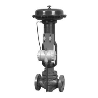
W4273-1
SLIDING-STEM
ACTUATOR MOUNTING
Figure 1. Typical 4200 Series Position Transmitters
Transmitter Circuit
Position Switch Circuit
. . . . . . . . . . . . . . . . . . . . . . . . . . . . . . . .
Introduction
Scope of Manual
This instruction manual provides installation,
operating, calibration, maintenance, and parts
ordering information for the 4200 Series electronic
position transmitters (figure 1). Refer to separate
Instruction Manuals for information on the actuator
and valve.
W4274-1
ROTARY
ACTUATOR MOUNTING
. . . . . . . . . . . . . . . . . . . . . . . . . . . . .
. . . . . . . . . . . . . .
. . . . . . . . . . . . . . . . . . . . . .
. . . . . . . . . . . . . . . . . .
. . . . . . . . . . . . . . . . . . . . . . . . . . . .
. . . . . . . . . .
23
23
23
24
27
27
40
Advertisement
Table of Contents

Related Manuals for Emerson Fisher 4210


Summary of Contents for Emerson Fisher 4210
- Page 1 Incorporates Errata Sheet dated February 2009 − see page 43 Instruction Manual Form 5596 4200 Series Transmitters November 2006 4200 Series Electronic Position Transmitters Contents Introduction ....... Scope of Manual .
-
Page 2: Form
1. and D carefully reading and understanding the contents of this manual. If you have any questions about these instructions, contact your Emerson Process Managementt sales office. WARNING Description This product is intended for a specific... - Page 3 Instruction Manual Form 5596 4200 Series Transmitters November 2006 Table 1. Specifications Available Configurations Operating Influences See table 2 Ambient Temperature : For a 56_C (100_F) change in normal operating conditions, maximum zero shift is ±0.5%; maximum span shift is Input Signal ±0.75% of span Source: Single potentiometer is standard or a...
- Page 4 Instruction Manual Form 5596 4200 Series Transmitters November 2006 Table 2. Available Configurations TRAVEL ELECTRICAL TYPE DUAL Standard Stroke Long Stroke TRANSMITTER POSITION NUMBER POTENTIOMETER Up to 105 mm Up to 610 mm SWITCHES (Up to 4.125 Inches) (Up to 24 Inches) −...
-
Page 5: Installation
Instruction Manual Form 5596 4200 Series Transmitters November 2006 PORT TRANSMITTER 1/2-INCH NPT FIELD WIRING COMPARTMENT (2 PLACES) COMPARTMENT (4.00) (6.25) (2.00) 5/16-18UNC 13 DEEP (0.53) (2.00) (4.00) (2 PLACES) BOTTOM VIEW (1.38) 6 (0.25) DIA. POTENTIOMETER (3.00) SHAFT (2.62) (2.62) (0.81) ALLOW 254 mm (10 INCHES) -
Page 6: Special Instructions For Safe Use And Installations In Hazardous Locations
Instruction Manual Form 5596 4200 Series Transmitters November 2006 Table 5. Hazardous Area Classifications for Canada—CSA CERTIFICATION TEMPERATURE ENCLOSURE TYPE CERTIFICATION OBTAINED ENTITY RATING BODY CODE RATING = 30 Vdc (Intrinsic Safety) = 150 mA Class/Division t 71°C) 4211, 4221 = 1.0 W T4 (T Class I,II,III Division 1 GP A,B,C,D,E,F,G... -
Page 7: Atex Intrinsic Safety, Dust
Instruction Manual Form 5596 4200 Series Transmitters November 2006 Table 6. Hazardous Area Classifications for United States—FM CERTIFICATION TEMPERATURE ENCLOSURE TYPE CERTIFICATION OBTAINED ENTITY RATING BODY CODE RATING = 30 Vdc (Intrinsic Safety) = 150 mA Class/Division t 71°C) 4211, 4221 = 1.0 W T4 (T Class I,II,III Division 1 GP A,B,C,D,E,F,G... -
Page 8: Rotary-Shaft Actuator Mounting
Instruction Manual Form 5596 4200 Series Transmitters November 2006 actuator stem. Replace the stem connector cap Rotary-Shaft Actuator Mounting, screws with the two cap screws (key 35) furnished Type 4210, 4211, 4212, and 4215 with the stem mounting bracket. Use the following general procedures and figures 19, 3. - Page 9 Instruction Manual Form 5596 4200 Series Transmitters November 2006 housing (key 100A). Lock the coupling in place by CAUTION tightening the inboard socket cap screw (key 100F). 10. Turn the potentiometer shaft (key 5) to the To avoid damaging the potentiometer midpoint of it’s range.
-
Page 10: Electrical Connections
Instruction Manual Form 5596 4200 Series Transmitters November 2006 5. Attach the mounting plate to the actuator using (hazardous area, ingress protection hex head cap screws (key 75). Note: Some and temperature). Failure to use actuators may require spacers (key 101) between properly rated wiring and/or cable the mounting plate (key 63) and the actuator. - Page 11 Instruction Manual Form 5596 4200 Series Transmitters November 2006 TRANSMITTER FIELD WIRING RELAY RETURN FIELD WIRING COMPARTMENT FIELD CIRCUIT PRINTED POWER WIRING BOARD SUPPLY − EARTH GROUND DEVICE RECEIVING 4 TO 20 MA DC SIGNAL − POSITION SWITCH DEVICE FIELD WIRING RECEIVING LO GROUNDING TERMINAL...
- Page 12 Instruction Manual Form 5596 4200 Series Transmitters November 2006 Connect a wire from the receiving device positive CAUTION (+) terminal to the (−) terminal on the barrier strip. 4. Connect the grounding terminal (key 58) to an Connect the transmitter grounding earth ground.
- Page 13 Instruction Manual Form 5596 4200 Series Transmitters November 2006 must be with a meter approved for Note hazardous areas. For sliding stem applications, tighten the set screw (key 26, figure 15) in the Refer to figure 5 for component locations. operating arm (key 30) to a torque of 3.39 to 3.95 NSm (30 to 35 lbfSin).
- Page 14 Instruction Manual Form 5596 4200 Series Transmitters November 2006 TOP COMPONENT SIDE (VIEWED FROM TOP SIDE) IDENTIFICATION LABEL Figure 5. Transmitter Printed Wiring Board Assembly...
- Page 15 Instruction Manual Form 5596 4200 Series Transmitters November 2006 FIELD WIRING FEEDTHROUGH TRANSMITTER TRANSMITTER FIELD CIRCUIT PRINTED COMPARTMENT PORT PRINTED WIRING COMPARTMENT WIRING BOARD BOARD FILTER BROWN WIRES FROM GROUNDING ORANGE RFI FILTER TERMINALS POTENTIOMETER O-RINGS SHAFT END VIEW CUTAWAY SIDE VIEW END VIEW FOR TYPE 4210, 4215, OR 4220 TRANSMITTER WITH POSITION SWITCHES AND FOR TYPE 4212 OR 4222 POSITION SWITCHES WITHOUT THE TRANSMITTER...
- Page 16 Instruction Manual Form 5596 4200 Series Transmitters November 2006 FOR ROTARY ACTUATORS Transmitter Transmitter Actuator Stem Input Potentiometer Type Actuator Style Set Position Switch Current Output, Action Travel Rotation Milliampere Down Direct Down 4210 Down Reverse Down Down Direct 4212 Down Reverse Not available for position switches without transmitter...
-
Page 17: Test Equipment Required
Instruction Manual Form 5596 4200 Series Transmitters November 2006 D A Type 4212 or 4222 position switch (without 4222 connect a voltmeter between TP5 (+) and TP6 the transmitter) obtains stem position from the input (−) to measure potentiometer position. potentiometer and provides position switch outputs from relays K1 and K2 (figures 4 and 9). -
Page 18: Compartment
Instruction Manual Form 5596 4200 Series Transmitters November 2006 VIEW A (SEE VIEW A) TO RFI FILTERS J1 FROM RFI FILTERS + 24 VOLT DC POWER SUPPLY FIELD WIRING TRANSMITTER COMPARTMENT COMPARTMENT NOTES: CONNECT DVM TO TEST POINTS AS DIRECTED BY CALIBRATION AND MAINTENANCE PROCEDURES. - Page 19 Instruction Manual Form 5596 4200 Series Transmitters November 2006 2. Connect the transmitter as shown in figure 8. High and Low Position Switch Adjustment 3. Remove the transmitter covers. 4. Stroke the valve or device to the mid-stroke Note position The “high”...
-
Page 20: Setting The High Position Switch Deadband
Instruction Manual Form 5596 4200 Series Transmitters November 2006 Note Setting the Low Position Switch Note The potentiometers are 25 turn trimpots with a slip clutch. To set Perform the high position switch these potentiometers at their adjustment procedures before maximum counterclockwise position, adjusting the low position switch. -
Page 21: Principle Of Operation
Instruction Manual Form 5596 4200 Series Transmitters November 2006 TRANSMITTER 24 VOLT DC POWER SUPPLY FIELD CIRCUIT TRANSMITTER PRINTED WIRING PRINTED WIRING − BOARD BOARD TRANSMITTER CIRCUIT DEVICE RECEIVING 4 TO 20 MA DC SIGNAL − MECHANICAL CONNECTION SWITCHING DEVICE TO DEVICE RELAY CIRCUIT... - Page 22 Instruction Manual Form 5596 4200 Series Transmitters November 2006 NOTES: RELAYS K1 AND K2 ARE SHOWN IN THE DE-ENERGIZED POSITION (TRIPPED POSITION). 29A6206-D / DOC Figure 10. Schematic Diagram for the Field Printed Wiring Board circuit input. Each of the position switch circuit (+) terminal and the (+) terminal on TB3.
- Page 23 Instruction Manual Form 5596 4200 Series Transmitters November 2006 Maintenance Table 8. Test Procedure (also refer to figure 11) CONNECT DVM TO STEP DVM READS (+) Lead (−) Lead WARNING 2.46 to 2.54 V dc (VREF) 14.1 to 16.1 V dc (+15) 2.46 to 2.54 V dc To avoid personal injury or property (VREF2)
- Page 24 Instruction Manual Form 5596 4200 Series Transmitters November 2006 wiring board(s), or by replacing the pot/bushing recommended. Return the instrument to the assembly (key 3, figures 12 and 14) depending on factory for repair. which is defective. b. If V2 and V3 are correct, continue with the 3.
- Page 25 Instruction Manual Form 5596 4200 Series Transmitters November 2006 Figure 11. Transmitter Printed Wiring Board Table 9. Jumper Configuration TYPE CIRCUIT PWB ASSEMBLY JUMPERS INSTALLED 4211/4221 Transmitter Only GE15866X012 W4, W5 (C1 Removed) 4210/4220 Transmitter with Alarms GE15866X022 W1, W2, W4, W5, W6 4212/4222 Alarm Switches Only GE15866X032...
- Page 26 Instruction Manual Form 5596 4200 Series Transmitters November 2006 APPLY LUBRICANT OR SEALANT NOTES: ON 4212, 4222, USE KEY 35 INSTEAD OF KEY 19 AT THE “−”FEEDTHROUGH POSITION, OMIT KEY 10 49A7893 M / IL Figure 12. Housing Assembly for Type 4210, 4215, or 4220 Transmitter with Position Switches and for Type 4212 or 4222 Position Switches without Transmitter Field Circuit Printed Wiring Board Pot/Bushing Assembly Replacement...
-
Page 27: Parts List
Parts Ordering Parts List When corresponding with your Emerson Process Management sales office about this equipment, Transmitter Common Parts always mention the transmitter serial number. When (Figures 12 and 14) - Page 28 Instruction Manual Form 5596 4200 Series Transmitters November 2006 APPLY LUBRICANT OR SEALANT 49A7891-L / IL Figure 14. Housing Assembly for Type 4211 or 4221 Transmitter without Position Switches Description Part Number Description Part Number Thread Locking Adhesive (medium strength) (not furnished with transmitter) Machine Screw, SST Anti-seize lubricant (not furnished with transmitter)
- Page 29 Instruction Manual Form 5596 4200 Series Transmitters November 2006 PICK-UP PIN TRAVEL, CONNECTION mm (Inch) NUMBER OPERATING HEX NUT Up to 54 (2.125) max Up to 105 (4.125) max PICK-UP PIN ACTUATOR YOKE ACTUATOR STEM CONNECTION TRANSFER LEVER ASSEMBLY HEX CAP SCREW PICK-UP PIN IN PICKUP PIN...
- Page 30 Instruction Manual Form 5596 4200 Series Transmitters November 2006 Description Part Number Description Part Number Shoulder Screw, heat treated stainless steel 10B5722X012 Cap Screw, pl steel (2 req’d) 1C631224052 Stem Bracket, zn pl steel Stem Bracket, zn pl steel 16A8277X012 Size 30 thru 100 Stem Mounting Bracket, zn pl steel w/ 54 mm (2.125 inch) max travel...
- Page 31 Instruction Manual Form 5596 4200 Series Transmitters November 2006 STEM BRACKET VIEW INDENT 1 INDENT 2 INDENT 3 INDENT 4 INDENT MARK TRAVEL INDENT NUMBER INCHES 0.75 1.125 FOR SIZES 25 AND 50 39A7636-D / DOC STEM BRACKET VIEW INDENT 1 INDENT 2 INDENT 3 INDENT 4...
- Page 32 Instruction Manual Form 5596 4200 Series Transmitters November 2006 37B4775-A / DOC Figure 17. Typical Transmitter Mounting on Type 585C or 585CR Actuator Parts for Mounting the Transmitter on Description Part Number Lever Assembly Type 585 or 585C Actuators (figures 16 Size 100 w/ 0.75 thru 2.125 inch travel 16A6705X012 and 17)
- Page 33 Instruction Manual Form 5596 4200 Series Transmitters November 2006 APPLY LUBRICANT 40B7441−A / DOC Figure 18. Typical Transmitter Mounting on Type 1250 or 1250R Actuator Description Part Number Description Part Number Stem Bracket, steel Size 225, 450 30B6736X012 Size 675 30B7385X012 Parts for Mounting the Transmitter on Sleeve, acetal...
- Page 34 Instruction Manual Form 5596 4200 Series Transmitters November 2006 APPLY LUBRICANT 49A7766-B / DOC Figure 19. Typical Transmitter Mounting on Type 1051, 1052, or 1061 Actuator Description Part Number Description Part Number Mounting Parts for Rotary Actuators Cap Screw, pl steel (2 req’d) 1C631224052 Anti-seize lubricant (not furnished with transmitter) Parts for Mounting the Transmitter on...
- Page 35 Instruction Manual Form 5596 4200 Series Transmitters November 2006 NOTE: FIELD MOUNTING PARTS APPLY LUBRICANT APPLY LUBRICANT 34A8843-B / DOC 34A8841-A / DOC Figure 21. Typical Transmitter Mounting on Type 1063, 1064, 1065, 1066, or 1066SR Actuator Figure 20. Typical Transmitter Mounting on Type 1052, Parts for Mounting the Transmitter on Size 20 Only Actuator Type 1063, 1064, 1065, 1066, or 1066R...
- Page 36 Instruction Manual Form 5596 4200 Series Transmitters November 2006 SECTION A−A TRANSDUCER ASSEMBLY GE13433 GE16564 Figure 22. Typical Transmitter Mounting on a Type 470-16 Actuator (585C with Travel Greater than 4-inches)
- Page 37 Instruction Manual Form 5596 4200 Series Transmitters November 2006 Mounting Parts for Long Stroke Sliding Description Part Number Stem Actuators Mounting Plate, stainless steel Yoke boss 5H, Parts for Mounting the Transmitter on Cylinder size 127 to 254 mm (5 to 10 inches), Max travel Type 470-16 Actuator (585C with travel 305 mm (12 inches) and...
- Page 38 Instruction Manual Form 5596 4200 Series Transmitters November 2006 SECTION A−A 77 86 GE13430 TRANSDUCER ASSEMBLY GE16563 Figure 23. Typical Transmitter Mounting on a Type 490 (585CLS) Actuator...
- Page 39 Instruction Manual Form 5596 4200 Series Transmitters November 2006 Description Part Number Description Part Number Cap Screw, stainless steel, (4 req’d) Lockwasher, stainless steel 1A3291X0012 Yoke boss 5H, Washer, pl steel (6 req’d), (not shown) 1F230328992 Cylinder size 127 to 254 mm (5 to 10 inches), Transducer Assy Max travel 305 mm (12 inches) and...
- Page 40 November 2006 Loop Schematics and Nameplates This section includes loop schematics required for wiring of intrinsically safe installations. It also contains the approvals nameplates. If you have any questions, contact your Emerson Process Management sales office. GE16020 Figure 24. CSA Schematic...
- Page 41 Instruction Manual Form 5596 4200 Series Transmitters November 2006 GE16019 Figure 25. FM Schematic...
- Page 42 Instruction Manual Form 5596 4200 Series Transmitters November 2006 TYPE 4211 AND 4221 TYPE 4210, 4212, 4215, 4220, AND 4222 INTRINSIC SAFETY, EXPLOSION PROOF, EXPLOSION PROOF, DUST-IGNITION PROOF DUST-IGNITION PROOF Figure 26. CSA and FM Approval Nameplates INTRINSIC SAFETY AND DUST TYPE n AND DUST Figure 27.
-
Page 43: Instruction Manual
1. A = No degradation during testing. B = Temporary degradation during testing, but is self-recovering. Fisher is a mark owned by one of the companies in the Emerson Process Management business division of Emerson Electric Co. Emerson Process Management, Emerson, and the Emerson logo are trademarks and service marks of Emerson Electric Co. All other marks are the property of their respective owners. - Page 44 November 2006 Fisher is a mark owned by Fisher Controls International LLC, a member of the Emerson Process Management business division of Emerson Electric Co. Emerson Process Management, Emerson, and the Emerson logo are trademarks and service marks of Emerson Electric Co.