Raymarine AXIOM Advanced Operation Instructions
Touch screen multifunction navigation display
Hide thumbs
Also See for AXIOM:
- Basic operation instructions (60 pages) ,
- Installation instructions manual (114 pages) ,
- Advanced operation instructions (152 pages)

Related Manuals for Raymarine AXIOM


Summary of Contents for Raymarine AXIOM
- Page 1 Advanced operation instructions LIGHTHOUSE v3.2xx English (en-US) Date: 09-2017 Document number: 81370-3 © 2017 Raymarine UK Limited...
- Page 2 Would you prefer a printed version of this document? Full documentation for your product is always provided as a free download on the Raymarine website, but some customers prefer manuals in a printed format. Raymarine provides a Print Shop service which enables you to purchase a printed manual (paperback book), delivered to your door.
- Page 3 Software updates Check the Raymarine website for the latest software releases for your product. www.raymarine.com/software Product documentation The latest versions of all English and translated documents are available to download in PDF format from the website: www.raymarine.com/manuals.
-
Page 5: Table Of Contents
Radar standby........................23 Autopilot shortcuts........................23 Adjusting brightness ......................23 3.5 Memory card compatibility....................24 Removing MicroSD card from its adaptor ................24 Inserting a MicroSD card — Axiom variants ................24 Inserting a MicroSD card — Axiom Pro variants..............25 3.6 Software updates ......................26... - Page 6 Selecting display language....................37 Boat details ...........................38 Units of measure........................38 Data master ..........................39 NMEA 0183 settings — Axiom Pro ..................40 4.7 Man Overboard (MOB) ....................... 41 MOB mode..........................41 4.8 Alarms ..........................42 4.9 Satellite navigation / positioning ..................43 GNSS Status .........................43...
- Page 7 Chapter 6 General app settings ..................57 6.1 Sidebar ..........................58 Customizing Sidebar data....................58 Switching sidebars....................... 58 6.2 Data overlays ........................59 6.3 Editing the split ratio of a Splitscreen app page ............60 6.4 App settings menus ......................61 Chapter 7 Waypoints, Routes and Tracks ..............
- Page 8 Chapter 9 Sonar app......................91 9.1 Sonar app overview ......................92 Sonar app controls....................... 92 RealVision 3D controls......................93 9.2 Opening the Sonar app ....................95 9.3 Sonar channels ........................98 Selecting a Sonar channel ....................98 9.4 Placing a Waypoint (Sonar, DownVision and SideVision) ..........99 Placing a waypoint RealVision 3D ..................
- Page 9 13.4 Audio app menu options....................153 Audio app settings menu....................153 Chapter 14 Mobile app support ................... 155 14.1 Raymarine mobile apps....................156 14.2 Connecting a mobile device to your MFD ..............157 14.3 Controlling your MFD using RayControl...............158 14.4 Controlling your MFD using RayRemote ..............159 14.5 Viewing your MFD screen using RayView..............160...
- Page 10 15.8 Wireless display troubleshooting.................. 175 15.9 Data troubleshooting...................... 176 15.10 Touchscreen troubleshooting..................177 Chapter 16 Technical support..................179 16.1 Raymarine product support and servicing..............180 Viewing product information ....................181 16.2 Learning resources......................182 Appendix A NMEA 0183 sentence support ..............183 Appendix B NMEA 2000 PGN support ...............184...
-
Page 11: Chapter 1 Important Information
Raymarine is not responsible for damages or injuries caused by your use or inability to use the product, by the interaction of the product with products manufactured by others, or by errors in chart data or information utilized by the product and supplied by third parties. -
Page 13: Chapter 2 Document And Product Information
Chapter 2: Document and product information Chapter contents • 2.1 Product documentation on page 14 Document and product information... -
Page 14: Product Documentation
Autorouting • Added C-Map cartography features — See Chart settings • Added support for distributed analog video on an Axiom Pro — See 12.1 Camera app overview • Software update process now includes compatible SeaTalkng devices — See 3.6 Software updates •... -
Page 15: Chapter 3 Set Up
Chapter 3: Set up Chapter contents • 3.1 Controls — Axiom variants on page 16 • 3.2 Controls — Axiom Pro variants on page 18 • 3.3 Getting started on page 19 • 3.4 Shortcuts on page 23 • 3.5 Memory card compatibility on page 24 •... -
Page 16: Controls - Axiom Variants
3.1 Controls — Axiom variants Touchscreen Power button MicroSD card reader (7” MicroSD card reader (9” & 12” displays) display only) Powering on the display When power is available to the MFD but the MFD is switched off, the Power symbol will be illuminated. -
Page 17: Powering Off The Display
Powering off the display 1. Swipe your finger from left to right across the Power button swipe area. The Shortcuts menu is displayed. 2. Press and hold the Power symbol until the screen switches off. Note: When powered off, the unit may still draw a small amount of power from the battery, if this is a concern unplug the power supply or switch off at the breaker. -
Page 18: Controls - Axiom Pro Variants
3.2 Controls — Axiom Pro variants In addition to its touchscreen, the Axiom Pro also includes physical buttons that can be used to control the MFD. Touchscreen — The touchscreen can be used to control the MFD. 2. Home — Press to display the Homescreen. -
Page 19: Getting Started
3.3 Getting started First power up When you power up your new Multifunction Display (MFD) for the first time a number of actions are required. The list below shows the actions that should be performed on your new MFD: Power on the display. 2. -
Page 20: First Power Up Limitation On Use Acknowledgement
For MDS to be available all products in the system that use the data sources, must be MDS-compliant. The system will report any products that are NOT MDS-compliant. It may be possible to upgrade the software for these products, to make them compliant. Visit the Raymarine website (www.raymarine.com) to obtain the latest software for your products. -
Page 21: Identifying Engines
Each tab enables you to view and select your preferred data source. The currently active data source will display its current value in use. Data source selection can be manual or set to automatic: • Auto — your MFD will automatically select a device. •... -
Page 22: Assigning A Function To The User Programmable Button
Assigning a function to the User Programmable Button You can assign a function to the User Programmable Button on an Axiom™ Pro MFD. 1. Press and hold the User Programmable Button. 2. Select the function from the list. You can also assign a function to the User Programmable Button from the Settings menu: Homescreen >... -
Page 23: Shortcuts
3.4 Shortcuts The Shortcuts menu can be accessed by swiping left to right across the Power button swipe area. The following shortcuts are available: • Take Screenshot • Activate Touchlock • Stop Radar transmitting • Power off • Engage / Disengage autopilot •... -
Page 24: Memory Card Compatibility
MicroSD memory and cartography chart cards are usually supplied inserted into an SD card adaptor. The card will need to be removed from the adaptor before inserting into your display. Inserting a MicroSD card — Axiom variants 1. Pull back the microSD card reader cover as shown above. -
Page 25: Inserting A Microsd Card - Axiom Pro Variants
2. Remove the MicroSD card from the Rear of the MFD. 3. Ensure you close the card reader’s cover. Inserting a MicroSD card — Axiom Pro variants 1. Open the card reader door. 2. Pull down the card reader cover. -
Page 26: Software Updates
• To check which products are compatible with the MFD software update process please refer to the website: www.raymarine.com/software. Updating software using a memory card Axiom™, Axiom™ Pro and compatible SeaTalkng ® products can be updated by following the steps below. 1. Check the software version of your product. - Page 27 3. To set up a Wi-Fi connection select Wi-Fi settings and connect to the required Wi-Fi access point/hotspot. 4. Select Start and then follow any onscreen instructions. Set up...
-
Page 28: Device Pairing
3.7 Device pairing Pairing a RMK remote keypad You can control your MFD with an RMK keypad. From the This display tab of the Settings menu: Homescreen > Settings > This display . 1. Select Pair keypad. 2. Follow the onscreen instructions to pair your keypad. Ensure you select the correct orientation for the keypad during the pairing process. -
Page 29: Chapter 4 Homescreen
Chapter 4: Homescreen Chapter contents • 4.1 Accepting the Limitations on Use on page 30 • 4.2 Homescreen overview on page 31 • 4.3 Creating / Customizing an App page on page 32 • 4.4 User profiles on page 33 •... -
Page 30: Accepting The Limitations On Use
4.1 Accepting the Limitations on Use After your MFD has powered up the Homescreen is displayed. 1. Before using the MFD you must accept the Limitations on Use (LoU) disclaimer. To view the full LoU Disclaimer, select ‘more details’. The LoU acknowledgment is displayed each time the display is powered on and for each new user profile. -
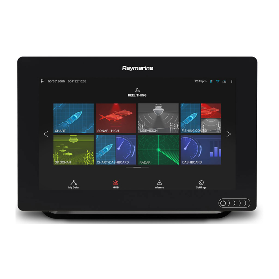
Page 31: Homescreen Overview
4.2 Homescreen overview All settings and apps can be accessed from the Homescreen. GNSS position/fix details — Select the area to view fix accuracy and access GNSS settings. 2. Profile — Select the area to change the profile in use or to create, edit or delete profiles. 3. -
Page 32: Creating / Customizing An App Page
4.3 Creating / Customizing an App page 1. Press and hold on an existing App page icon to display pop-over options. You can Customize, Rename or Delete app pages from the pop-over options. 2. Select Customize from the pop-over options to change page layout and apps used. To Create a new page press and hold on a blank space on the Homescreen. -
Page 33: User Profiles
4.4 User profiles You can share your MFD with other users by creating user profiles on your MFD. Profiles enable you to retain your own personal settings whilst letting other users personalize the MFD’s settings to their preference. Note: User data such as Waypoints, Routes, Tracks, images and video recordings etc. will be available to all users. - Page 34 Selecting a Demo profile will provide your MFD with simulated data to help you practice operating your display. Important: • It is recommended that Demo profiles are NOT activated whilst navigating. • Demo profiles will NOT display any real data, including safety warnings and messages. •...
-
Page 35: My Data
4.5 My data Selecting the My data icon from the Homescreen provides access to user data such as Waypoints, Routes, Tracks, Trip data and media Files. You can also Import/export User data from the My data menu. Selecting Waypoints, Routes or Tracks will take you to the relevant list where you can manage and customize your data. -
Page 36: Files
• Trip (manual) — accumulates data until reset. • Trip (day) — resets automatically when local time passes midnight. • Trip (month) — resets automatically on the 1st day of the month. • Trip (season) — accumulates data until reset. The manual trip log can be reset directly from the My data page by selecting Reset man. -
Page 37: Settings
• View software and network details for the MFD you are using. • Save or Erase diagnostics logs to external storage. • Set up NMEA 0183 options on an Axiom Pro. • Assign your preferred data sources. Selecting display language You can choose which language you want the MFD to use. -
Page 38: Boat Details
Available user interface languages The following languages are available: English (US) English (UK) Arabic Danish German Greek Spanish Finnish French Indonesian Icelandic Italian Japanese Korean Lithuanian Latvian Dutch Norwegian Polish Portuguese Russian Swedish Turkish Vietnamese Chinese (Traditional) Chinese (Simplified) Boat details To ensure correct operation and display of data you should set the Boat Details settings according to your requirements. -
Page 39: Data Master
Measurement Units Measurement Units • Meters • Knots Depth units: Wind speed units: • Feet • Meters per Second • Fathoms • Celsius • Bar Temperature units: Pressure units: • PSI • Fahrenheit • Kilopascals Date format: • MM:DD:YYYY • 12hr Time format: •... -
Page 40: Nmea 0183 Settings - Axiom Pro
NMEA 0183 settings — Axiom Pro NMEA 0183 devices can be connected to Axiom Pro MFDs using the NMEA 0183 wires on the supplied Power/Video/NMEA 0183 cable.. 2 NMEA 0183 ports are available: • Port 1: Input and output, 4,800 or 38,400 baud rate. -
Page 41: Man Overboard (Mob)
4.7 Man Overboard (MOB) If a person or object falls overboard, you can use the Man Overboard (MOB) feature to mark the position that your vessel was at when the MOB alarm was activated. The MOB feature can be activated by pressing and holding on the MOB icon: on the Homescreen or the waypoint/MOB icon: found at the top of all apps. -
Page 42: Alarms
4.8 Alarms The Alarm manager can be accessed from the Homescreen. Example: Active alarms list Alarms are raised by system functions, and also external equipment connected to your display. When an Alarm is triggered all networked MFDs will display audible and visual warnings. The onscreen warning provides details of why the alarm has been triggered. -
Page 43: Satellite Navigation / Positioning
4.9 Satellite navigation / positioning GNSS Status Your vessel’s GNSS position is provided in the top left corner of the Homescreen. You can access fix accuracy and settings by selecting the area. If latitude and longitude is displayed on the Homescreen then you have a valid position fix. If the text turns red then your fix accuracy is low. - Page 44 • enable and disable your MFD’s internal GNSS receiver. Disable if you do not want to use this unit’s internal GNSS receiver as a source for positioning data. • restart the GNSS receiver that is being used as the source for your positioning data.
-
Page 45: Status Area
4.10 Status area You can view the status of peripheral devices connected to your MFD using the Status area, located at the top right of the Homescreen. This area also provides the Time and identifies when the MFD is in Touchlock mode. Status area icons The status of connected AIS, Radars Sonars/Transducers are reported in the Status area: pop-over menu options... -
Page 46: Connecting To A Wireless Display
4.11 Connecting to a wireless display Your MFD can be connected to a wireless display using an external dongle or a display that has built-in support. When connected the MFDs screen is mirrored on the wireless display. 1. Follow the instructions provided with your wireless display/dongle to set up the device. 2. -
Page 47: Unpairing A Wireless Display
Unpairing a wireless display With the wireless display connection active: 1. Select the connected display from the Wireless display menu: (Homescreen > Settings > This Display > Wireless Display:). 2. Select the connected display from the list of available displays. 3. -
Page 49: Chapter 5 Autopilot Control
Chapter 5: Autopilot control Chapter contents • 5.1 Autopilot control on page 50 • 5.2 Autopilot Control — Advanced settings on page 54 Autopilot control... -
Page 50: Autopilot Control
5.1 Autopilot control Your MFD can be integrated with an Evolution autopilot system and act as the autopilot’s controller. Please refer to the documentation supplied with your autopilot for details on installing and connecting your autopilot to your MFD. Autopilot control from your MFD can be enabled and disabled from the Autopilot tab in the Settings menu: Homescreen >... -
Page 51: Engaging And Disengaging The Autopilot - Physical Buttons
Engaging and disengaging the autopilot - physical buttons The process for engaging your autopilot using the physical buttons available on a RMK remote keypad or an Axiom Pro is shown below. 1. Press and hold the Pilot button to engage the autopilot in Locked heading mode. - Page 52 Pilot sidebar — Standby Sidebar selection Enables you to switch between Pilot and Data sidebars. Close Closes the Pilot sidebar. Steer to Hdg Enables you to engage the autopilot in locked heading (Auto) mode. Steer to Nav Enables you to engage the autopilot in Navigation (Track) mode.
-
Page 53: Pilot Pop-Up
Pilot sidebar — Navigation (Track) Destination Displays your current destination. User customizable data Displays user customizable data. Select to customize data. Advance wpt Selecting will advance your destination to the next waypoint in the current route. Stop Route / Stop Goto Selecting will stop current navigation. -
Page 54: Autopilot Control - Advanced Settings
5.2 Autopilot Control — Advanced settings Menu item Description Options Vessel hull type Selecting the hull type that is the closest match • Sail for your vessel provides optimum steering • Sail (slow turn) performance. • Sail Catamaran • Power •... - Page 55 Menu item Description Options ACU debug level Sets a debug value for troubleshooting • 0 to 63 purposes. The debug level should only be set when requested by Technical Support as part of a troubleshooting process. Rudder damping in used to prevent the •...
-
Page 57: Chapter 6 General App Settings
Chapter 6: General app settings Chapter contents • 6.1 Sidebar on page 58 • 6.2 Data overlays on page 59 • 6.3 Editing the split ratio of a Splitscreen app page on page 60 • 6.4 App settings menus on page 61 General app settings... -
Page 58: Sidebar
6.1 Sidebar The Sidebar is available in all apps and provides quick access to system data. By default the Sidebar is set up to display navigation data. The Sidebar is displayed automatically in the Chart app when a Goto or follow is initiated. It can also be displayed at anytime by sliding your finger from left to right from the left edge of the screen. -
Page 59: Data Overlays
6.2 Data overlays System data can be overlaid onto the Chart app, Radar app, Sonar app and Camera app. Some apps have Data overlays enabled by default. Data overlays can be placed anywhere on the app page and can be placed over any app in a Splitscreen app page. -
Page 60: Editing The Split Ratio Of A Splitscreen App Page
6.3 Editing the split ratio of a Splitscreen app page With a Splitscreen app page displayed: 1. Select Edit split ratio from the Page settings tab: Menu > Settings > Page settings > Edit split ratio. 2. Drag the Resize icon to create the desired split ratio. 3. -
Page 61: App Settings Menus
6.4 App settings menus Each app includes a settings menu that provides access to app settings and features. The settings menu in each app is signified by the Settings icon. General app settings... -
Page 63: Chapter 7 Waypoints, Routes And Tracks
Chapter 7: Waypoints, Routes and Tracks Chapter contents • 7.1 Waypoints on page 64 • 7.2 Routes on page 67 • 7.3 Tracks on page 71 Waypoints, Routes and Tracks... -
Page 64: Waypoints
7.1 Waypoints Waypoints are used to mark specific locations or points of interest. Waypoints can be used in the Chart, Radar and Sonar apps. Your MFD can store up to 10,000 waypoints which can be sorted into up to 200 waypoint groups. In the Chart app you can navigate to a waypoint by selecting Goto from the Waypoint context menu. - Page 65 From the Waypoint list you can Search for a waypoint, Create a New group, Create a New Waypoint or Delete a waypoint group. Selecting a Waypoint group from the list displays a list of all waypoints in that group. Group lists If the Waypoint list is accessed from the Chart app menu, the selected group or waypoint is displayed in a Chart pane on the right of the screen.
- Page 66 Waypoint details The details for the waypoint can be customized by selecting the relevant field. You can also Delete the waypoint, set a Goto, or View on chart.
-
Page 67: Routes
Routes are used to plan your journey in advance. You can plan your journey directly on your MFD, or at home using software capable of exporting Waypoints and Routes in standard .gpx format, such as Raymarine’s Voyage Planner software. Routes consist of a number of waypoints. Your MFD can store up to 250 Routes, each Route consisting of up to 500 waypoints. -
Page 68: Autorouting
Autorouting Autorouting is available when using compatible cartography. Autorouting allows you to build a route automatically between a point on the chart and your vessel. You can select any point on the Chart and from the Chart context menu select Autoroute to here or you can select Autoroute to from an existing waypoint’s context menu to create a route automatically between your vessel and the chosen point. -
Page 69: Route Management
Route management Routes are managed using the Route list. The Route list can be accessed from the Homescreen and from the Chart app: Homescreen > My data > Routes, or Chart app > Menu > Waypoints, routes, tracks > Routes. If the Route list is accessed from the Chart app menu, then the selected route is displayed in a Chart pane on the right of the screen. - Page 70 • add an existing waypoint to the route by selecting Add waypoint • change route options by selecting Route options By selecting a waypoint from the route plan you can change the waypoint order by moving the waypoint up and down the list. You can also remove the waypoint from the list, delete the waypoint, edit the waypoint details or start the Route follow from any waypoint in the route.
-
Page 71: Tracks
7.3 Tracks Tracks are used to record where you have been. Tracks are made up of track points that are created at regular time or distance intervals. You can store up to 15 tracks on your MFD, each track can contain up to 10,000 points. - Page 72 Track list From the track list you can Start or Stop tracks recording, Delete a track or choose how tracks are recorded. Track interval The track interval determines the time period or distance between track points when recording a track. You can choose whether to record track points by Time, by Distance or set to Auto. •...
-
Page 73: Chapter 8 Chart App
Chapter 8: Chart app Chapter contents • 8.1 Chart app overview on page 74 • 8.2 Navigation on page 81 • 8.3 Target tracking on page 82 • 8.4 Chart settings menu on page 87 Chart app... -
Page 74: Chart App Overview
8.1 Chart app overview The Chart app displays a representation of your vessel in relation to land masses and other charted objects, which enables you to plan and navigate to your desired destination. The Chart app requires a GNSS position fix in order to display your vessel at the correct location on a world map. For each instance of the Chart app you can select which electronic cartography that you want to use, the selection will persist over a power cycle. -
Page 75: Chart App Controls
Chart app controls Icon Description Action Home icon Takes you to the Homescreen Waypoint / MOB Place waypoint / hold down to activate Man overboard (MOB) alarm Pilot icon Opens and closes the Pilot Sidebar Menu icon Opens the app menu Find vessel Centers your vessel onscreen. -
Page 76: Selecting A Chart Card
• Context menus are accessed in the Chart app by pressing and holding on a location or object. • The context menu provides Latitude, longitude, range and bearing details for the selected location or object. • The context menu provides quick access to relevant settings or features. -
Page 77: Chart Modes
Chart modes The Chart app provides preset modes that can be used to quickly set up the Chart app for your intended use. To change Chart mode select the required mode from the app menu. DETAILEDTo change Radar mode select the required mode from the Radar app menu. -
Page 78: Object Selection And Information
• offset the position of the vessel symbol. • change the symbol used to represent your vessel. • set the length of vessel vectors. • show / hide Heading and COG vectors. • show / hide Range Rings. • show / hide Tide and Wind graphics. Object selection and information Charted objects, available on your cartography can be selected and object information can be viewed. -
Page 79: Layers
Layers Layers are available that can overlaid on the Chart app. Layers include Aerial photographs, AIS targets, Radar image, Range rings, Tide graphs, and Crowd sourced content. The Layers tab from the Chart app Settings menu: Menu > Settings > Layers provides controls for Chart layers. -
Page 80: Camera Tracking
Chart orientation The orientation of the chart affects the alignment of the chart relative to your vessel, route or North. Boat position Adjust the boat position to allow more or less ‘look ahead’ space in front of your boat. Camera tracking When connected to a compatible Pan and Tilt Thermal camera you can track targets or point your camera at a specific target or area. -
Page 81: Navigation
8.2 Navigation Navigating to a waypoint or point of interest You can perform a “Goto” to a Waypoint or specific location. 1. Select and hold on the waypoint or point of interest and select Goto from the context menu. You can stop the Goto at any time by selecting and holding anywhere in the Chart app and choosing Stop, or selecting another Goto. -
Page 82: Target Tracking
8.3 Target tracking With compatible AIS and Radar hardware connected to your MFD, you can track AIS and Radar targets. AIS targets can be tracked in the Chart app and Radar targets can be tracked in the Radar app and also in the Chart app, when the Radar layer is switched on. When targets are being tracked they appear in the AIS or Radar targets list. -
Page 83: Dangerous Targets Alarm
The vectors can be set to True or Relative. The Vector length identifies where the target will be after the specified time has passed. You can adjust the length of the vector by selecting a time from the Vector length pop-over options. AIS vectors can be set to All (displayed for all targets) or Manual (only displayed when turned on using the target’s context menu). -
Page 84: Radar Settings
To set up the Dangerous target alarm, first adjust the Safe distance to the desired value and then select a Time to reach safe distance. The alarm will be triggered if a tracked target will reach the specified Safe distance from your vessel within the time period selected. You can select whether you want the Dangerous target alarm to track Radar targets, AIS targets or both. - Page 85 Setting Description Options When enabled AIS target • On Hide static targets travelling under 2 knots will • Off be hidden, unless they are or become dangerous. When enabled your vessel’s • On Silent mode AIS will not transmit your •...
- Page 86 AIS symbol status Lost (No border, crossed Uncertain (Dashed outline) through) Buddy (Yellow fill) Dangerous and Uncertain (Dashed outline and Flashes Red) Dangerous (Flashes Red) ATON off position (Red border)
-
Page 87: Chart Settings Menu
8.4 Chart settings menu The table below lists settings applicable to the Chart app and their location within the app’s Settings menu. Available settings are dependent on the cartography in use. If a setting is not displayed then the feature is not compatible with your cartography. If a feature is grayed out then it requires a subscription to activate the feature. - Page 88 Depths tab Settings Description Options Vendor Enables and disables display of depth • None • LightHouse Show soundings soundings on the chart. When set to (Vector) • Manual Manual depth soundings will be shown • Navionics from zero to the maximum depth you •...
- Page 89 View & Motion tab Settings Description Options • Relative motion Chart motion Relative motion In Relative motion the vessel icon remains fixed • True motion onscreen and the chart area moves relative to • Auto range your position. In Relative motion mode you can adjust your vessel’s fixed position using the Boat position setting.
- Page 90 Settings Description Options Enables and disables display of cartographic • Navigation marks Cartographic objects objects. The settings available are dependent on • Navigation mark the cartography in use. symbols • Rocks • Light sectors • Routing systems • Caution areas •...
-
Page 91: Chapter 9 Sonar App
Chapter 9: Sonar app Chapter contents • 9.1 Sonar app overview on page 92 • 9.2 Opening the Sonar app on page 95 • 9.3 Sonar channels on page 98 • 9.4 Placing a Waypoint (Sonar, DownVision and SideVision) on page 99 •... -
Page 92: Sonar App Overview
9.1 Sonar app overview The Sonar app displays a visualization of the echoes received from a Sonar module and transducer. The Sonar app is compatible with Traditional, CHIRP, DownVision™, SideVision™ and RealVision™ 3D sonar modules and transducers. The Sonar app builds an underwater view of bottom structure and targets in the water column. -
Page 93: Realvision 3D Controls
Icon Description Action Image adjustment Displays onscreen sensitivity / image adjustment controls Pause Pause RealVision™ 3D sonar image. Unpause When the Sonar app is paused, you can recommence scrolling by selecting the Unpause icon. Range/Zoom In When Auto range is enabled, pressing the plus icon activates Zoom mode, subsequent presses will increase the Zoom factor. - Page 94 • Pinch-to-zoom changes the magnification of the image. • The Range control determines how far the sonar will ping. • Press and hold onscreen to display the context menu Physical buttons • Ok button pauses Sonar scrolling. • Back button resumes Sonar scrolling. •...
-
Page 95: Opening The Sonar App
The Sonar app is opened by selecting a page icon from the Homescreen that includes a Sonar app. Pre-requisites: Ensure your Sonar module is compatible (check the latest details available on the Raymarine website). If in doubt please contact an authorized Raymarine dealer for advice. - Page 96 No sonar source available If the ’No sonar source available’ warning is displayed then either: • your sonar module is still powering up. • your MFD cannot establish a connection with your external Sonar module • your Internal Sonar module has no transducer connected. Check your external sonar module’s network and power connection, check your MFD’s network or transducer connection ensuring the connections and cabling is correct and free from damage, then power cycle your system.
- Page 97 Check your transducer connection(s) are correct and free from damage, then power cycle your system. If the transducer is still not found then refer to your equipment’s installation documentation for further troubleshooting information. Sonar app...
-
Page 98: Sonar Channels
9.3 Sonar channels The Sonar channels that are available depend on the Sonar module and transducer you have connected. RealVision™ 3D SideVision™ DownVision™ High CHIRP / High Frequency Medium CHIRP / Medium Low CHIRP / Low Frequency Frequency Selecting a Sonar channel The first time you open a new Sonar app page you will be requested to select a channel, subsequently you can change the sonar channel by selecting a channel icon from the Sonar app menu. -
Page 99: Placing A Waypoint (Sonar, Downvision And Sidevision)
9.4 Placing a Waypoint (Sonar, DownVision and SideVision) When you observe something of interest in the Sonar app you can place a waypoint at its location so that you can find the area again. 1. Select and hold on the point of interest onscreen. The Context menu is displayed and scrolling is paused, temporarily. - Page 100 3. Select Move position to adjust the marker’s position before creating the waypoint. You can move the waypoint along its current axis by sliding 1 finger across the screen. You can also adjust the view onscreen using the usual 2 finger touch gestures. 4.
-
Page 101: Sonar Scroll Back
9.5 Sonar scroll back You can “scroll back” in the Sonar app to view sonar history. To activate sonar “scroll back”, perform the following: • Sonar and DownVision — Swipe your finger left to right across the sonar screen. • SideVision — Swipe your finger from the bottom to the top of the sonar screen. •... -
Page 102: Sonar Sensitivity Controls
9.6 Sonar sensitivity controls Optimum performance is usually achieved using the default settings. You can adjust the image using the Sensitivity controls to improve the displayed image. Sensitivity setting adjustment is also applied to the sonar history that is displayed when using sonar scroll back. Sensitivity settings can be accessed using the onscreen Image adjustment icon, or the Adjust sensitivity menu option: Menu >... -
Page 103: Sonar Settings Menu
9.7 Sonar settings menu The table below lists settings applicable to the Sonar app and their location within the app Settings menu. The settings available are dependant upon the Sonar module in use. Sonar display tab Settings Description Options Various color palettes are available to suit Color palette List of color palettes. - Page 104 Settings Description Options Background Changes the color used for the app background. List of colors. View mode In GPS track mode the boat icon will remain • GPS track in the same position and bottom structure and • Scrolling image target detail will move in true relation to your vessel movements.
- Page 105 Settings Description Options On sonar modules that offer simultaneous dual • Auto Dual channel ping mode channel operation, such as the CP570, The ping • Independent pings mode can be changed. Auto the Sonar app will select the best mode •...
-
Page 107: Chapter 10 Radar Application
Chapter 10: Radar application Chapter contents • 10.1 Radar app overview on page 108 • 10.2 Radar feature comparison on page 111 • 10.3 Opening the Radar app on page 114 • 10.4 Set up on page 116 • 10.5 Radar modes on page 118 •... -
Page 108: Radar App Overview
10.1 Radar app overview The Radar app displays a visualization of the echoes received from a connected Radar scanner. The Radar app is an aid used to help enhance collision and situational awareness by enabling target’s distance and speed to be tracked in relation to your vessel. Up to 2 Radar scanners can be connected at the same time. -
Page 109: Radar App Context Menu
Icon Description Action Image adjustment Displays onscreen sensitivity / image adjustment controls Power Off Powers down the current Radar scanner Powers up the selected Radar scanner Power On Transmit Start Radar transmission Range In Decreases the distance displayed onscreen (minimum range: 1/16nm). - Page 110 • Track with camera — Tracks a selected target regardless of your own vessel’s or target’s course. Camera tracking options are available from the Context menu in the Chart and Radar apps: Context menu > more options > Point camera here, or Context menu > more options > Track with camera. Automatic tracking You can use the Camera app settings to configure automatic tracking for AIS, Radar and MoB targets: Camera app >...
-
Page 111: Radar Feature Comparison
10.2 Radar feature comparison The range of features and settings that are available in the Radar app is dependent on the type of connected Radar scanner. Sensitivity controls Features/settings Radar type • All Gain Color Gain • Quantum™ • SuperHD™ Open Array •... - Page 112 Features/settings Radar type Radar Targets • Quantum™ = 10 • SuperHD™ Open Array = 25 • HD Open Array = 25 • HD Radome = 25 • Digital Radome = 10 Tuning • SuperHD™ Open Array • HD Open Array •...
-
Page 113: Compatible Radar Scanners
Compatible Radar scanners The table below lists Radar scanners that can be used with the Radar app. • Quantum™. • SuperHD™ Open Array. • HD Open Array. • HD Radome. • Digital Radome. Radar application... -
Page 114: Opening The Radar App
The Radar app is opened by selecting a page icon from the Homescreen that includes the Radar app. Pre-requisites: Ensure your Radar scanner is compatible, check the latest details available on the Raymarine website, if in doubt please contact an authorized Raymarine dealer for advice. -
Page 115: Putting The Radar Into Standby
Standby (Not transmitting) If the ‘Standby’ message is displayed then select Transmit to begin transmitting. Transmitting If your Radar scanner is connected, powered up and transmitting then the Radar image is displayed and echoes/targets are displayed onscreen. Putting the Radar into Standby With your selected Radar displayed onscreen: 1. -
Page 116: Set Up
10.4 Set up Selecting a Radar scanner On systems with 2 Radar scanners, you can select which Radar scanner is used in each instance of the Radar app. 1. Select the Settings icon from the Radar app menu. 2. Select the Scanner: box on the Transmission tab. A list of available Radar scanners is displayed. -
Page 117: Timed Radar Transmission
Dual range limitations: • Dual range cannot be enabled when Radar targets are being tracked (clear the target list and try again). • When Dual range is enabled Radar target tracking is disabled. • When Dual range is enabled Automatic Radar target acquisition is disabled. •... -
Page 118: Radar Modes
10.5 Radar modes The Radar app provides preset modes that can be used to quickly achieve the best picture depending on your current situation. Only Radar modes supported by your Radar scanner are shown. To change Radar mode select the required mode from the Radar app menu. HARBOR Harbor mode takes into account land clutter that is typically encountered in a Harbor, so that smaller targets are still... -
Page 119: Range And Bearing
10.6 Range and bearing The Radar app helps you identify a target’s range (distance) and bearing from your vessel. SHM (Ships heading marker). 2. COG/SOG line (Points in the direction of travel (COG), with the length of the vector providing an indication of speed (SOG)). - Page 120 Centered VRM/EBLYou can use a ‘Centered’ (on your vessel) VRM/EBL to determine the range and bearing of targets in relation to your vessel. 2. Floating VRM/EBLYou can use a ‘Floating’ VRM/EBL to determine the range and bearing between 2 targets. Editing a VRM-EBL Once a VRM/EBL has been placed you can adjust its size and position.
-
Page 121: Target Tracking
10.7 Target tracking The Radar app can be used to acquire and track targets. When a target is being tracked it will be displayed in the Radar target list. The target lists can be accessed by selecting Targets from the app menu: Menu > Targets . Selecting a target from the list will highlight the selected target in the app pane on the right of the screen. -
Page 122: Radar Target Symbols
Radar target symbols Symbol Status Description Acquiring target — Manual Thin dashed Green circle Acquiring target — Auto Thick dashed Red circle, flashes until acknowledged Auto-acquired target — Red circle, flashes until acknowledged Unacknowledged Acquired target Green circle with Target ID Dangerous target Red circle with Target ID, flashes until acknowledged... - Page 123 Target vectors The vectors can be set to True or Relative. The Vector length identifies where the target will be after the specified time has passed. You can adjust the length of the vector by selecting a time from the Vector length pop-over options. Additional CPA and target information can be displayed for each target using the context menu (select a target to display the context menu).
-
Page 124: Dangerous Targets Alarm
Dangerous targets alarm You can use the Dangerous targets alarm to notify you if a target will reach a specified distance from your vessel within a specified time. To set up the Dangerous target alarm, first adjust the Safe distance to the desired value and then select a Time to reach safe distance. - Page 125 A Guard zone can be configured as a sector or as a circle around your vessel. Selecting Adjust Zone allows you to configure the size of the Guard Zone. Adjust the guard zone size by dragging the inner and outer perimeter end points (circles) to the desired locations.
-
Page 126: Radar Sensitivity Controls
10.8 Radar sensitivity controls Optimum performance is usually achieved using the default settings. You can adjust the image using the Sensitivity controls to improve the displayed image. Sensitivity settings can be accessed using the onscreen Image adjustment icon, or the Adjust sensitivity menu option: Menu >... -
Page 127: Radar Settings
10.9 Radar settings The Settings menu provides access to the Radar app’s features and functions. The options available in the Settings menu are dependent on the type of Radar scanner connected. Transmission tab Settings Description Options Scanner Allows you to select the Radar scanner that you List of available Radar want to use. - Page 128 Settings Description Options screen, the image is redrawn to reveal the area ahead. In True motion mode the boat position is fixed to Full offset. The boat position determines the position of • Center Boat position your vessel onscreen. You can adjust the Boat •...
- Page 129 Installation tab Under normal circumstances it should not be necessary to adjust Installation settings. Settings Description Options Bearing alignment Enables you to align the Radar image correctly • 179.5° Port to 180° in relation to your vessel’s bow. Starboard Parking offset Allows you to select the ‘parked position of your •...
-
Page 131: Chapter 11 Dashboard App
Chapter 11: Dashboard app Chapter contents • 11.1 Dashboard app overview on page 132 • 11.2 Dashboard settings menu on page 134 Dashboard app... -
Page 132: Dashboard App Overview
11.1 Dashboard app overview The Dashboard app enables you to view system data. System data may be generated by your MFD or by devices connected to your MFD via SeaTalkng ® / NMEA 2000 and SeaTalkhs ™. The Dashboard app can also be configured to provide control of your compatible Digital Switching devices. Note: For data to be available in the Dashboard app it must be being transmitted to your MFD from compatible hardware using supported protocols and messages. -
Page 133: Navigation And Sailing Dials
Navigation and Sailing dials Navigation and Sailing dials are available which provide a compass dial with various data indicators. Navigation dial 2. Sailing dial 3. Apparent Wind Angle (AWA) indicator 4. True Wind Direction (TWD) indicator 5. Apparent Wind Angle (AWA) 6. -
Page 134: Dashboard Settings Menu
• Reset all Import custom You can import custom pages that have been Displays file browser pages created using approved PC based page creation software. Please refer to Raymarine Product support for more details. Circuits tab Settings Description Options List of tripped In Digital Switching systems the Circuit tab •... - Page 135 Settings Description Options Determines how bearing and heading data is • True Bearing mode displayed. • Magnetic System Datum Determines the datum used by your MFD. List of available datums. This should be set to the same datum used by your paper charts.
-
Page 137: Chapter 12 Camera App
Chapter 12: Camera app Chapter contents • 12.1 Camera app overview on page 138 • 12.2 Opening the Camera app on page 140 • 12.3 Camera settings on page 142 Camera app... -
Page 138: Camera App Overview
12.1 Camera app overview IP (Internet Protocol) video feeds and analog camera feeds available via an Axiom™ Pro MFD can be viewed, recorded and played back using the Camera app. Examples of video feeds include: CCTV cameras and Thermal imaging cameras. It may be possible to view analog video feeds from other sources using a suitable Analog to IP video converter. -
Page 139: Pan, Tilt, Zoom (Ptz) Camera Controls
Icon Description Function Stop Stop recording (Replaced Record icon when not recording.) Take photo Take a photo of what is currently displayed in the active feed. Pan, Tilt, Zoom (PTZ) camera controls Extra controls are available for cameras that can pan, tilt or zoom. Swiping your finger across the screen to pan or tilt the camera. -
Page 140: Opening The Camera App
The Camera app is opened by selecting an app page from the Homescreen that includes the Camera app. Pre-requisites: Ensure your camera is compatible by checking the latest details available on the Raymarine website against your IP camera’s specification. If in doubt please contact an authorized Raymarine dealer for advice. -
Page 141: Selecting A Video Feed
• a Camera app page is opened for the first time and no compatible camera is connected. • a Camera app page is opened for the first time before the camera has finished booting up. If the ‘No camera detected’ message is displayed for more than 2 minutes, then your MFD cannot connect to your camera. -
Page 142: Camera Settings
12.3 Camera settings The Settings menu provides access to the Camera app’s features and functions. The options available in the Settings menu are dependent on your system configuration and connected Cameras. Cycling tab Settings Description Options Determines the time each camera will be Cycle Delay •... - Page 143 Photo & Video recording tab Settings Description Options Determines the save location for photos and • SD 1 Save files to: video recordings. • External SD 1 USB Media Note: External SD 1 and USB Media are available when using the RCR-SDUSB Accessory.
-
Page 145: Chapter 13 Audio Application
Chapter 13: Audio application Chapter contents • 13.1 Audio app overview on page 146 • 13.2 Opening the Audio app on page 149 • 13.3 Getting started on page 151 • 13.4 Audio app menu options on page 153 Audio application... -
Page 146: Audio App Overview
Compatible entertainment systems The table below shows compatible NMEA 2000 entertainment systems, that have been approved for use with the Audio app. Manufacturer Raymarine model number Raymarine part number Rockford Fosgate RMX8DH E70394... -
Page 147: Audio App Controls
Audio app controls Icon Description Function Home icon Takes you to the Homescreen. Waypoint / MOB Place waypoint / activate Man overboard (MOB) alarm. Pilot icon Opens and closes the Pilot Sidebar Menu icon Opens the app menu. Power Off Powers off the Entertainment system. - Page 148 Icon Description Function Repeat • Off • Repeat Track • Repeat All Shuffle • On • Off Play Select to commence playback. Pause Select to Pause playback. Stop Select to Stop (Mute) Radio devices. Like Like a track (Pandora only). Dislike Dislike a track (Pandora only).
-
Page 149: Opening The Audio App
Ensure your Entertainment system is compatible by checking the latest details available on the Raymarine website. If in doubt please contact an authorized Raymarine dealer for advice. 2. Ensure you have installed your Entertainment system in accordance with the documentation that was supplied with the system. - Page 150 No audio devices found If the ‘No audio device found’ message is displayed for more than 10 seconds, then your MFD cannot connect to your Entertainment system. Ensure network and power connections to your Entertainment system and MFD are correct and free from damage and then power cycle your system.
-
Page 151: Getting Started
13.3 Getting started Selecting an audio source 1. Select the audio source you want to listen to from the app Menu. Before you can select an audio source from your MFD, the source must already be available to your Entertainment system’s main control unit (“head unit”). Muting and unmuting 1. -
Page 152: Saving Presets
Saving presets Up to 4 presets can be saved for each Radio audio source (i.e.: AM Radio, FM Radio, Weather, SiriusXM and Pandora). 1. Whilst listening to the station you want to save, press and hold the relevant Preset button for approximately 3 seconds. -
Page 153: Audio App Menu Options
13.4 Audio app menu options Menu item Description Options Tracks Enables you to browse for tracks on • Folder USB/Bluetooth devices connected to your • Play Queue Entertainment system Channels Provides a list of available SiriusXM Channel list channels Stations Provides a list of available Pandora stations Station list Enables you to select an audio source... -
Page 155: Chapter 14 Mobile App Support
Chapter 14: Mobile app support Chapter contents • 14.1 Raymarine mobile apps on page 156 • 14.2 Connecting a mobile device to your MFD on page 157 • 14.3 Controlling your MFD using RayControl on page 158 • 14.4 Controlling your MFD using RayRemote on page 159 •... -
Page 156: Raymarine Mobile Apps
14.1 Raymarine mobile apps Please check the relevant app store for Raymarine mobile apps. Note: When updating your MFD software ensure that you check for updates to your mobile apps. -
Page 157: Connecting A Mobile Device To Your Mfd
14.2 Connecting a mobile device to your MFD 1. Open the Wi-Fi settings on your mobile device and select your product’s Wi-Fi Name / SSID from the list of available networks. You can establish your MFD’s SSID and Passphrase by selecting Configure from the This display tab of the Settings menu: Homescreen >... -
Page 158: Controlling Your Mfd Using Raycontrol
4. Control your MFD using your mobile device’s touchscreen in the same way you would interact with the MFD’s touchscreen. 5. You can also use a representation of an Axiom Pro’s or RMK remote’s physical buttons by sliding the controls sidebar out from the right of the screen or on smaller devices selecting... -
Page 159: Controlling Your Mfd Using Rayremote
2. Ensure your mobile device is connected to your MFD’s Wi-Fi. 3. Open the RayRemote app. 4. Control your MFD on your mobile device using the on-screen equivalents of the physical buttons found on the Axiom Pro MFD or RMK remote keypad. Mobile app support... -
Page 160: Viewing Your Mfd Screen Using Rayview
14.5 Viewing your MFD screen using RayView The RayView app allows you to remotely view your MFD from your mobile device. 1. Download and install RayView from your app store. 2. Ensure your mobile device is connected to your MFD’s Wi-Fi. 3. -
Page 161: Chapter 15 Troubleshooting
Chapter 15: Troubleshooting Chapter contents • 15.1 Troubleshooting on page 162 • 15.2 Power up troubleshooting on page 163 • 15.3 Radar troubleshooting on page 164 • 15.4 GNSS troubleshooting on page 166 • 15.5 Sonar troubleshooting on page 167 •... -
Page 162: Troubleshooting
If after referring to this section you are still having problems with your product, please refer to the Technical support section of this manual for useful links and Raymarine Product Support contact details. -
Page 163: Power Up Troubleshooting
In the unlikely event that the product’s software has become corrupted, try downloading and installing the latest software from the Raymarine website. 2. On display products, as a last resort, attempt to perform a ‘Power on Reset’. Be aware that this will delete all settings / presets and user data (such as waypoints and tracks), and revert the unit back to factory defaults. -
Page 164: Radar Troubleshooting
Open Array • Ensure Open Array power switch is in the On position. power in Off position Software • Ensure all Raymarine products contain the latest available software, check the mismatch Raymarine website: www.raymarine.com/software for software compatibility. between... - Page 165 Displayed bearing is different to the true bearing Possible Causes Possible Solution Bearing • Carry out the Bearing Alignment procedure. alignment adjustment required Radar will not initialize (Voltage control module (VCM) stuck in “sleep mode” Possible Causes Possible Solution Intermittent or Check power connection at VCM.
-
Page 166: Gnss Troubleshooting
15.4 GNSS troubleshooting No fix displayed Possible causes Possible solutions Geographic location or prevailing conditions Check to see if a fix is obtained in better preventing satellite fix. conditions or another geographic location. GNSS connection fault. Ensure that external GNSS connections and cabling are correct and fault free. -
Page 167: Sonar Troubleshooting
Check all connections ensuring connections are secure, problem. clean and free from corrosion, replace if necessary. External sonar module: Ensure all Raymarine products contain the latest available software, Software mismatch between check the Raymarine website: www.raymarine.com/software equipment may prevent software compatibility. - Page 168 Possible causes Possible solutions Damaged cables Check the unit’s connector for broken or bent pins. 2. Check that the cable connector is fully inserted into the unit and that the locking collar is in the locked position. 3. Check the cable and connectors for signs of damage or corrosion, replace if necessary.
- Page 169 Possible causes Possible solutions Transducer location • Check that the transducer has been installed in accordance with the instructions provided with the transducer. • If a transom mount transducer is mounted too high on the transom it may be lifting out of the water, check that the transducer face is fully submerged when planing and turning.
-
Page 170: Camera Troubleshooting
15.6 Camera troubleshooting Video not displayed Possible causes Possible solutions Incorrect power up sequence Your MFD needs to be powered up before your camera to enable the MFD to provide the camera with a valid IP address. Camera not compatible. Ensure the camera feed and network settings are compatible: •... - Page 171 Noisy image Possible causes Possible solutions Poor quality or faulty cabling. • Ensure cable runs are no longer than they need to be. • Use only high quality shielded cable suitable for the marine environment. Cable is picking up • Ensure you are using a high quality shielded cable. electromagnetic interference •...
-
Page 172: Wi-Fi Troubleshooting
15.7 Wi-Fi troubleshooting Before troubleshooting problems with your Wi-Fi connection, ensure that you have followed the Wi-Fi location requirements guidance provided in the relevant installation instructions and performed a power cycle/reboot of the devices you are experiencing problems with. Cannot find network Possible cause Possible solutions Wi-Fi not currently enabled on devices. - Page 173 Possible cause Possible solutions Interference caused by other devices that use Temporarily switch off each device in turn until the 2.4GHz frequency See list below of some you have identified the device causing the common devices that use the 2.4GHz frequency: interference, then remove or reposition the offending device(s).
- Page 174 Mobile application running slowly or not at all Possible cause Possible solutions Raymarine app not installed Install mobile app from relevant app store. Raymarine app version not compatible with MFD Ensure mobile app and MFD software are latest software available versions. Mobile apps not enabled on MFD Enable “Viewing only”...
-
Page 175: Wireless Display Troubleshooting
Poor performance Possible cause Possible solutions High video processing demand. The Camera app, Raymarine mobile app connections can interfere with the wireless display performance as they use shared video processing resource. Try switching off video feeds and/or mobile app connections. -
Page 176: Data Troubleshooting
• Check power to the data bus. Software mismatch between equipment may • Check the Raymarine website and ensure prevent communication. all your Raymarine products have the latest software. Instrument or other system data is missing from some but not all displays... -
Page 177: Touchscreen Troubleshooting
15.10 Touchscreen troubleshooting Touchscreen does not operate as expected. Possible causes Possible solutions Touch lock is enabled. Disable TouchLock, using the power button.. Screen is not being operated with bare fingers, Bare fingers must make contact with the screen for example gloves are being worn. for correct operation. -
Page 179: Chapter 16 Technical Support
Chapter 16: Technical support Chapter contents • 16.1 Raymarine product support and servicing on page 180 • 16.2 Learning resources on page 182 Technical support... -
Page 180: Raymarine Product Support And Servicing
You can obtain this product information using the menus within your product. Servicing and warranty Raymarine offers dedicated service departments for warranty, service, and repairs. Don’t forget to visit the Raymarine website to register your product for extended warranty benefits: http://www.raymarine.co.uk/display/?id=788. Telephone... -
Page 181: Viewing Product Information
Denmark +45 437 164 64 support.dk@raymarine.com (Raymarine subsidiary) Russia +7 495 788 info@mikstmarine.ru 0508 (Authorized Raymarine distributor) Viewing product information The Getting started tab contains hardware and software information for your MFD. 1. Select Settings, from the Homescreen. Technical support... -
Page 182: Learning Resources
16.2 Learning resources Raymarine has produced a range of learning resources to help you get the most out of your products. Video tutorials Raymarine official channel on YouTube: • http://www.youtube.com/user/RaymarineInc Video Gallery: • http://www.raymarine.co.uk/view/?id=2679 Product Support videos: • http://www.raymarine.co.uk/view/?id=4952 Note: •... -
Page 183: Appendix A Nmea 0183 Sentence Support
Appendix A NMEA 0183 sentence support Sentence Description Transmit Receive • • Heading/Track controller pilot sentence “B” • • Bearing & distance to waypoint — great circle • • Bearing & distance to waypoint — rhumb line • • Depth below transducer Depth •... -
Page 184: Appendix B Nmea 2000 Pgn Support
Appendix B NMEA 2000 PGN support Description Transmit Receive • • 59392 ISO Acknowledgment • • 59904 ISO Request • • 60928 ISO Address Claim • • 126208 NMEA - Request group function • • 126464 Receive/Transmit PGN's group function •... - Page 185 • • 130578 Vessel Speed Components Raymarine® provides field programmability of the Device and System Instances within PGN 60928 which can be commanded via use of PGN 126208 as required by the latest NMEA 2000 standard. NMEA 2000 PGN support...
-
Page 186: Appendix C Document Change History
LH3.2 • Updated software revision to reflect LH3.2. • Updated New features section to reflect LH3.2. • Added User programmable button details for Axiom Pro MFDs. • Updated Software updates section to reflect updating SeaTalkng products. • Added wireless display information, connection details and troubleshooting. - Page 187 Document Software revision Date version Changes • Added camera tracking (Point camera here and Track with camera controls to Chart and Radar chapters. • Added details for placing waypoints in RV channels. • Added details of Sonar scroll back. • Added details of sensitivity adjustments effecting sonar scroll back.
- Page 189 Alarms ..............42 Contact details............180 App pages Controls Creating ...............32 Audio ..............147 Customizing ............32 Axiom..............16 Audio Axiom Pro ............18 Controls ..............147 Camera .............. 138 Auto turn..............55 Chart ..............75 Autopilot Dashboard ............132 Advanced settings ..........54 Radar ..............108 Control ..............
- Page 190 GNSS (GPS) Settings ..........43 Product support............. 180 GNSS/GPS troubleshooting........166 Goto waypoint ............81 GPS................43 Gybe ................55 Radar Color Gain............126 Controls ............. 108 Dual range ............116 Harbor mode ............118 Gain ..............126 Hard over time............55 Rain ..............
- Page 191 Scroll back ............101 Goto ..............81 Sensitivity controls ..........102 List ...............35 Surface filter............102 Placement ............99 TVG (Time Varied Gain) ........102 Weather mode............118 Waypoints ............99 Wind Zoom mode ............93 Data type .............55 Sonar logs ...............88 Shift..............55 SonarChart Live............88 Wireless display............46 Speed input .............54...
- Page 194 Raymarine Marine House, Cartwright Drive, Fareham, Hampshire. PO15 5RJ. United Kingdom. Tel: +44 (0)1329 246 700 www.raymarine.com a brand by...