Siemens SIMATIC ET 200MP Manual
Module
Hide thumbs
Also See for SIMATIC ET 200MP:
- System manual (126 pages) ,
- Equipment manual (72 pages) ,
- Manual (60 pages)
Table of Contents
Advertisement
Advertisement
Table of Contents

Related Manuals for Siemens SIMATIC ET 200MP


Summary of Contents for Siemens SIMATIC ET 200MP
- Page 2 ___________________ Preface ___________________ Documentation guide ___________________ SIMATIC Product overview ___________________ Wiring ET 200MP Interface module IM 155-5 PN ST ___________________ (6ES7155-5AA01-0AB0) Parameter ___________________ Interrupts and diagnostic, error, and system alarms Manual ___________________ Technical specifications ___________________ Dimension drawing ___________________ Response times 11/2017 A5E03612323-AC...
- Page 3 Note the following: WARNING Siemens products may only be used for the applications described in the catalog and in the relevant technical documentation. If products and components from other manufacturers are used, these must be recommended or approved by Siemens. Proper transport, storage, installation, assembly, commissioning, operation and maintenance are required to ensure that the products operate safely and without any problems.
-
Page 4: Preface
Siemens' products and solutions undergo continuous development to make them more secure. Siemens strongly recommends that product updates are applied as soon as they are available and that the latest product versions are used. Use of product versions that are no longer supported, and failure to apply the latest updates may increase customers' exposure to cyber threats. -
Page 5: Table Of Contents
Table of contents Preface ..............................4 Documentation guide ..........................6 Product overview ..........................11 Properties ..........................11 Functions ..........................13 2.2.1 PROFINET IO ......................... 13 2.2.2 Configuration control (option handling) ................... 19 Wiring ..............................20 Terminal assignment ....................... 20 Block diagram ......................... 22 Parameter ............................. -
Page 6: Documentation Guide
Documentation guide The documentation for the SIMATIC S7-1500 automation system and the SIMATIC ET 200MP distributed I/O system is arranged into three areas. This arrangement enables you to access the specific content you require. Basic information The System Manual and Getting Started describe in detail the configuration, installation, wiring and commissioning of the SIMATIC S7-1500 and ET 200MP systems. - Page 7 You must register once to use the full functionality of "mySupport". You can find "mySupport" on the Internet (https://support.industry.siemens.com/My/ww/en). "mySupport" - Documentation In the Documentation area in "mySupport" you can combine entire manuals or only parts of these to your own manual.
- Page 8 ● Manuals, characteristics, operating manuals, certificates ● Product master data You can find "mySupport" - CAx data on the Internet (http://support.industry.siemens.com/my/ww/en/CAxOnline). Application examples The application examples support you with various tools and examples for solving your automation tasks. Solutions are shown in interplay with multiple components in the system - separated from the focus on individual products.
- Page 9 You can find the SIMATIC Automation Tool on the Internet (https://support.industry.siemens.com/cs/ww/en/view/98161300). PRONETA With SIEMENS PRONETA (PROFINET network analysis), you analyze the PROFINET network during commissioning. PRONETA features two core functions: ● The topology overview independently scans PROFINET network and all connected components.
- Page 10 Documentation guide SINETPLAN SINETPLAN, the Siemens Network Planner, supports you in planning automation systems and networks based on PROFINET. The tool facilitates professional and predictive dimensioning of your PROFINET installation as early as in the planning stage. In addition, SINETPLAN supports you during network optimization and helps you to exploit network resources optimally and to plan reserves.
-
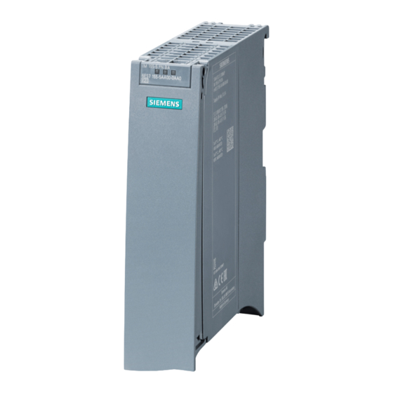
Page 11: Product Overview
Product overview Properties Article number 6ES7155-5AA01-0AB0 View of the module Figure 2-1 View of the IM 155-5 PN ST interface module Properties ● Technical properties – Connects the ET 200MP distributed I/O system with PROFINET IO – 24V DC power supply (SELV/PELV) –... - Page 12 Up to 12 I/O modules can be supplied this way. The exact number of operable modules is determined by the power budget (see relevant section in the ET 200MP distributed I/O system (https://support.industry.siemens.com/cs/ww/en/view/59191792) system manual). ● A maximum of one power supply module (PS) upstream from the interface module and two downstream from the interface module is possible.
-
Page 13: Functions
Product overview 2.2 Functions Functions 2.2.1 PROFINET IO Introduction The interface module supports the following PROFINET IO functions: ● Integrated switch with 2 ports ● Supported Ethernet services: ping, arp, SNMP, LLDP ● Port diagnostics ● Disabling ports ● Isochronous real-time communication ●... - Page 14 6ES7155-5AA01- with HSP 223) 0AB0 The usability of the PROFINET IO functions depends on the configuration software (Siemens and/or third party). Below, the usability of the PROFINET IO functions is described for STEP 7 only. Firmware version V2.0 or higher...
- Page 15 You can find additional information on configuration of synchronized PROFINET devices in sync domains in the STEP 7 online help and ● as of STEP 7 V12, in the PROFINET with STEP 7 V14 (https://support.industry.siemens.com/cs/ww/en/view/49948856) function manual. ● as of STEP 7 V5.5 in the PROFINET System Description (http://support.automation.siemens.com/WW/view/en/19292127) manual.
- Page 16 You can find additional information in the STEP 7 online help and ● as of STEP 7 V12, in the PROFINET with STEP 7 V14 (https://support.industry.siemens.com/cs/ww/en/view/49948856) function manual. ● as of STEP 7 V5.5 in the PROFINET System Description (http://support.automation.siemens.com/WW/view/en/19292127) manual.
- Page 17 IO devices that have been used in another configuration must be reset to the factory settings before they can be used again (see S7-1500, ET 200MP (http://support.automation.siemens.com/WW/view/en/59191792) system manual). You can find additional information in the STEP 7 online help and ●...
- Page 18 You can find more information on this topic in the STEP 7 online help and ● As of STEP 7 V14, in the PROFINET with STEP 7 V14 (https://support.industry.siemens.com/cs/ww/en/view/49948856) function manual. Isochronous mode of process data The process data, transmission cycles via PROFINET IO, and the user program are synchronized to achieve ultimate deterministic.
-
Page 19: Configuration Control (Option Handling)
Reference You can find more information ● in the S7-1500, ET 200MP system manual (http://support.automation.siemens.com/WW/view/en/59191792) ● on the Internet (http://support.automation.siemens.com/WW/view/en/29430270) ● in the STEP 7 online help. Interface module IM 155-5 PN ST (6ES7155-5AA01-0AB0) Manual, 11/2017, A5E03612323-AC... -
Page 20: Wiring
Wiring Terminal assignment 24V DC power supply The following table shows the signal names and the descriptions of the pin assignment for a 24 V DC supply voltage. Table 3- 1 Pin assignment 24 V DC supply voltage View Signal name Designation 24 V DC 24 V DC (for looping through) - Page 21 Wiring 3.1 Terminal assignment PROFINET interface X1 with 2-port switch (X1 P1 R and X1 P2 R) The pin assignment of the ports depends on the setting of the port option "Activate autonegotiation". ● Port P1 X1 R: When autonegotiation is deactivated, the RJ45 socket is allocated as data terminal equipment MDI (normal pin assignment).
-
Page 22: Block Diagram
Additional information You can find additional information on connecting the interface module and on accessories (RJ45 bus connector) in the ET 200MP distributed I/O system (https://support.industry.siemens.com/cs/ww/en/view/59191792) system manual. Block diagram Block diagram The following figure shows a block diagram of the IM 155-5 PN ST interface module. -
Page 23: Parameter
Parameter Parameters Table 4- 1 Parameters for IM 155-5 PN ST interface module Parameters Value range Default setting Efficiency range Connection to supply voltage Connection/No con- Connection ET 200MP nection Configuration control Disable/enable Disable ET 200MP Interface module IM 155-5 PN ST (6ES7155-5AA01-0AB0) Manual, 11/2017, A5E03612323-AC... -
Page 24: Description Of Parameters
Reference See the section on the power budget and the forming of power segments in the ET 200MP distributed I/O system (https://support.industry.siemens.com/cs/ww/en/view/59191792) System Manual. Interface module IM 155-5 PN ST (6ES7155-5AA01-0AB0) Manual, 11/2017, A5E03612323-AC... -
Page 25: Configuration Control
196 from the user program in order for the ET 200MP distributed I/O system to operate the I/O modules. Reference For more information on configuration control, refer to the S7-1500, ET 200MP system manual (https://support.industry.siemens.com/cs/ww/en/view/59191792) and to the STEP 7 online help. Interface module IM 155-5 PN ST (6ES7155-5AA01-0AB0) Manual, 11/2017, A5E03612323-AC... -
Page 26: Interrupts And Diagnostic, Error, And System Alarms
Interrupts and diagnostic, error, and system alarms Status and error displays Introduction Diagnostics by means of LED display is an initial tool for error localization. To further limit the error, you usually evaluate the display of the CPU, the display of the module status in STEP 7 or the diagnostics buffer of the CPU. - Page 27 Interrupts and diagnostic, error, and system alarms 5.1 Status and error displays Meaning of the LEDs RUN/ ERROR/ MAINT Table 5- 1 Meaning of the LEDs RUN/ ERROR/ MAINT LEDs Meaning Remedy ERROR MAINT Supply voltage not present at interface Check the supply voltage or turn it on at the module or too small interface module.
- Page 28 Interrupts and diagnostic, error, and system alarms 5.1 Status and error displays Meaning of the LEDs P1 LINK/TX/RX, P2 LINK/TX/RX Table 5- 2 Meaning of the LEDs P1 LINK/TX/RX, P2 LINK/TX/RX LEDs Meaning Remedy P1 LINK/TX/RX, P2 LINK/TX/RX There is no Ethernet connection between the Check whether the bus cable to the switch/IO PROFINET interface of your PROFINET device controller is interrupted.
-
Page 29: Interrupts
S7-1500 CPU, to the S7-1500 CPU web server, to the HMI device and in STEP 7. For additional information on the system diagnostics, refer to the System Diagnostics function manual. (https://support.industry.siemens.com/cs/ww/en/view/59192926). 5.2.1 Triggering of a diagnostic interrupt Triggering of a diagnostic interrupt For an incoming or outgoing event (e.g., wire break on a channel of an I/O module), the... -
Page 30: Triggering Of A Hardware Interrupt
Interrupts and diagnostic, error, and system alarms 5.3 Alarms 5.2.2 Triggering of a hardware interrupt Triggering of a hardware interrupt When a hardware interrupt occurs, the CPU interrupts execution of the user program and processes the hardware interrupt OB. The event that triggered the interrupt is entered in the start information of the hardware interrupt OB. - Page 31 Additional information on the data records for PROFINET IO You can find the structure of the diagnostic data records and programming examples in the programming manual From PROFIBUS DP to PROFINET IO (https://support.industry.siemens.com/cs/ww/en/view/19289930) and in the application example on the Internet (https://support.industry.siemens.com/cs/ww/en/view/24000238). Causes of error and troubleshooting The causes of error and troubleshooting of the diagnostic alarms are described in the device manuals of the I/O modules in the section Interrupts/Diagnostic alarms.
-
Page 32: Maintenance Events
Interrupts and diagnostic, error, and system alarms 5.3 Alarms 5.3.2 Maintenance events Triggering of a maintenance event The PROFINET interface of the interface module supports the diagnostic concept and maintenance concept in PROFINET according to the IEC 61158-6-10 standard. The goal is to detect and remove potential problems as soon as possible. -
Page 33: Channel Diagnostics
Interrupts and diagnostic, error, and system alarms 5.3 Alarms 5.3.3 Channel diagnostics Function Channel diagnostics provides information about channel faults in modules. Channel faults are mapped as channel diagnostic data in IO diagnostic data records. The "RDREC" instruction is used to read the data record. Structure of the diagnostic data records ●... - Page 34 Interrupts and diagnostic, error, and system alarms 5.3 Alarms Structure of the manufacturer-specific diagnostic data records (firmware version lower than V4.0) The structure of the diagnostic data records is differentiated by the BlockVersion. The following BlockVersion applies to the IM 155-5 PN ST interface modules: Table 5- 6 Structure of the manufacturer-specific diagnostic data records IM 155-5 PN ST interface module...
- Page 35 Interrupts and diagnostic, error, and system alarms 5.3 Alarms Structure USI = W#16#0002 Table 5- 9 Structure of the USI = W#16#0002 Data block name Contents Note Bytes W#16#0002 Manufacturer-specific diagnostic data if the permitted number of power supply modules is exceeded The first surplus module is located in slot: <No.>...
- Page 36 Interrupts and diagnostic, error, and system alarms 5.3 Alarms USI structure = W#16#0005 Table 5- 12 USI structure = W#16#0005 Data block name Contents Note Bytes W#16#0005 Manufacturer-specific diagnostic data if there is more than one bus master module (IM/CPU) Followed by 4 reserved bytes Reserved Reserved...
- Page 37 Followed by 3 reserved bytes Reserved Reserved Reserved Additional information You can find additional information on maximum configuration, power budget and power segments in the ET 200MP Distributed I/O System (https://support.industry.siemens.com/cs/ww/en/view/59191792) system manual. Interface module IM 155-5 PN ST (6ES7155-5AA01-0AB0) Manual, 11/2017, A5E03612323-AC...
-
Page 38: Invalid Configuration States Of The Et 200Mp On Profinet Io
Additional information You can find additional information on maximum configuration, power budget and power segments in the ET 200MP distributed I/O system (https://support.industry.siemens.com/cs/ww/en/view/59191792) System Manual. See also: Status and error displays (Page 26) 5.3.5 STOP of the IO controller and recovery of the IO device... -
Page 39: Technical Specifications
Technical specifications Technical specifications of the IM 155-5 PN ST Article number 6ES7155-5AA01-0AB0 General information Product type designation IM 155-5 PN ST HW functional status FS01 Firmware version V4.1.0 Vendor identification (VendorID) 0x002A Device identifier (DeviceID) 0X0312 Product function Yes; I&M0 to I&M3 I&M data •... - Page 40 Technical specifications Article number 6ES7155-5AA01-0AB0 Power Infeed power to the backplane bus 14 W Power available from the backplane bus 2.3 W Power loss Power loss, typ. 4.5 W Address area Address space per module 256 byte; per input / output Address space per module, max.
- Page 41 Technical specifications Article number 6ES7155-5AA01-0AB0 PROFINET IO Device Services – Isochronous mode – – – MRPD – PROFINET system redundancy – PROFIenergy – Prioritized startup – Shared device – Number of IO Controllers with shared device, max. Open IE communication TCP/IP •...
- Page 42 Technical specifications Article number 6ES7155-5AA01-0AB0 Ambient conditions Ambient temperature during operation 0 °C horizontal installation, min. • 60 °C horizontal installation, max. • 0 °C vertical installation, min. • 40 °C vertical installation, max. • Connection method ET-Connection via BU/BA Send •...
-
Page 43: Dimension Drawing
Dimension drawing The dimensional drawing of the module on the mounting rail, as well as a dimensional drawing with open front panel, are provided in the appendix. Always observe the specified dimensions for installation in cabinets, control rooms, etc. Dimensional drawings of the IM 155-5 PN ST interface module Figure A-1 Dimensional drawing of the IM 155-5 PN ST interface module, front and side views Interface module IM 155-5 PN ST (6ES7155-5AA01-0AB0) - Page 44 Dimension drawing Dimensional drawing of the IM 155-5 PN ST interface module, side view with open front cover Figure A-2 Dimensional drawing of the IM 155-5 PN ST interface module, side view with open front cover Interface module IM 155-5 PN ST (6ES7155-5AA01-0AB0) Manual, 11/2017, A5E03612323-AC...
-
Page 45: Response Times
Response times Response times of the ET 200MP Introduction The response time of the IM 155-5 PN ST is made up of: ● the update time configured for the IM as IO device. plus ● the backplane bus cycle time. Note Validity of the formula The following formula does not apply to shared device mode. - Page 46 Response times B.1 Response times of the ET 200MP Example configuration for the calculation of the backplane bus cycle time The following are used in the example: Table B- 1 Example configuration for the calculation of the backplane bus cycle time I/O module Output data Input data...
- Page 47 (PGs), HMI devices (Panels) or additional S7 stations, can be present as data receiving stations on the PROFINET line. You can find the measured values of the PROFINET response time for a typical configuration in this application example (https://support.industry.siemens.com/cs/ww/en/view/21869080). Interface module IM 155-5 PN ST (6ES7155-5AA01-0AB0) Manual, 11/2017, A5E03612323-AC...