
Related Manuals for FMS 2000MM Beaver DHC-2


Summary of Contents for FMS 2000MM Beaver DHC-2
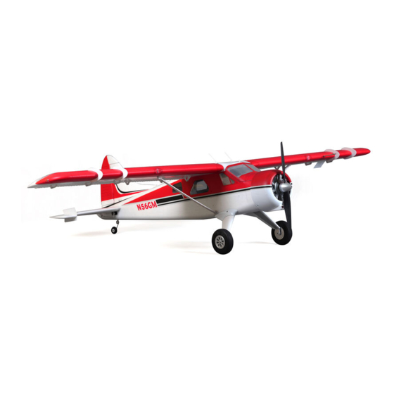
- Page 1 2000MM Beaver DHC-2 FMSMODEL.COM REALISTIC RIGID STABLE FLAPS INSTALLED STRONG DURABLE EPO SMOOTH FLYING PERFORMANCE...
-
Page 4: Table Of Contents
Over the years, FMS has been committed to developing different types of products to meet the diverse needs and interests of pilots. For FMS' first large propeller aircraft, we adopted all of the latest concepts and technologies to bring you a wonderful casual flight experience. -
Page 5: Contents Of Kit
Wingspan: 2000mm (78.7in) Overall Length: 1304mm (51.3in) Flying Weight: Around 3800g (134oz) Motor Size: Brushless 4258-KV550 Wing Load: 71.1 g/dm² (0.16oz/in²) Wing Area: 53.4 dm² ( sq.in) ESC: 70A Servo: 6g Servo x 17 Contents of Kit Before assembly, please inspect the contents of the kit. The photo below details the contents of the kit and labels. -
Page 6: Assembling The Plane
Horizontal Tail Installation 1.Slide the horizontal tail tube into the hole in rear of the fuselage 2.Install the 2 piece(left and right)horizontal tail as shown. Ensure the control horn faces down. 3.Install 4 screws in the front and rear holes in the button of the horizontal tail. 4.Attach the ball link to the elevator control horn’s outermost hole using the included nut and screw. -
Page 7: Vertical Stabilizer Installation
Vertical Stabilizer Installation Connect the rudder and elevator servo connectors to the servo extensions in the fuselage. Slide the vertical tail assembly into the slot in the fuselage. CAUTION: DO NOT crush or damage the wiring when attaching the vertical tail assembly to the fuselage. Secure the assembly to the fuselage using 2 screws as shown. -
Page 8: Wing Installation
Wing Installation Slide the tube into the fuselage then install both wings over the wing tube and into the wing slot of the fuselage. Notice: The connectors on both side should be attached precisely and firmly. fig10 fig11 Install the 2 wing struts on the fuselage mount using 2 R-clips. Make sure it is installed precisely. fig11 fig12 fig13... - Page 9 3.Secure the wings on the fuselage using 4 screws in the top of the wings. Make sure it is tightened enough. HKM3.0×26mm fig15 Removal We recommend removing the wings from the fuselage for storage or transport of the aircraft. 1. Carefully apply CA to the base and side of the front main wing 2.
- Page 10 Optional Towing Retract Installation 1.Install the retract to the top of fuselage with four screws as photo shows. 2.Install the cover on the retract with two screws. PA2.6×26mm fig19 fig20 fig20 fig21 KA2.0×10mm PA2.6×26mm KA2.0×10mm fig21 fig22...
-
Page 11: Optional Float Installation
Optional Float Installation Install the strut bar to both sides of the float. The front bar is longer with 422mm length, the rear bar is shorter with 412mm length. Wrong installation will cause difficulty landing and taking off (fig.24) 422mm 412mm fig23 2.Install the float strut to the float with 8 screws as picture shows. - Page 12 4.Connect the float rudder servo connector then tighten it on the strut with included cable ties. fig27...
-
Page 13: Battery And Radio Installation
Battery and radio installation fig28 fig28 RUDD GEAR AILE Float water rudder fig31 fig29 fig30 Note:If you have installed the optional retract for towing, use Channel 5 to operate. -
Page 14: Get Your Model Ready To Fly
Get your model ready to fly Important ESC and model information The ESC included with the model has a safe start. If the motor battery is connected to the ESC and the throttle stick is not in the low throttle or off position, the motor will not start until the throttle stick is moved to the low throttle or off position. -
Page 15: Check The Control Throws
Check the control throws The suggested control throw setting for FMS MODEL are as follows (dual rate setting): Tips: On first flight, fly the model in low rate. The first time you use high rates, be sure to fly at low to medium speeds. -
Page 16: Clevis Installation
Clevis Installation a. Pull the tube from the clevis to the linkage. b. Carefully spread the clevis, then insert the clevis pin into the desired hole in the control horn. c. Move the tube to hold the clevis on the control horn. -
Page 17: Install The Propeller And Spinner
Install the propeller and spinner Assemble the spinner and propeller as shown below. Check the C.G. (Center of Gravity) When balancing your model, adjust the motor battery as necessary so the model is level or slightly nose down. This is the correct balance point for your model. After the first flights, the CG position can be adjusted for your personal preference. -
Page 18: Before Flying The Model
Before flying the model Find a suitable flying site Find a flying site clear of buildings, trees, power lines and other obstructions. Until you know how much area will be required and have mastered flying your plane in confined spaces, choose a site which is at least the size of two to three football fields - a flying field specifically for R/C planes is best. -
Page 19: Flying Course
Flying course Take off While applying power, slowly steer to keep the model straight. The model should accelerate quickly. As the model gains flight speed you will want to climb at a steady and even rate. The Beaver will climb out at a nice angle of attack (AOA). -
Page 20: Troubleshooting
Troubleshooting... -
Page 21: Spare Parts List Content
Spare parts list content Fuselage FMSPQ101 FMSPQ102 Main Wing Set FMSPQ103 Horizontal Stabilizer FMSPQ104 Vertical Stabilizer FMSPQ105 Battery Hatch FMSPQ106 Antenna Foam Cover FMSPQ107 Cowl FMSPQ108 Spinner FMSPQ109 Engine FMSPQ110 Vortex Generator FMSPQ111 Airspeed Head Set FMSPQ112 Antenna FMSPQ113 Servo Cover FMSPQ114 Main Landing Gear Set FMSPQ115... -
Page 22: Esc Instruction
ESC instruction...