Table of Contents
Advertisement
Installation INSTRUCTION
GENERAL
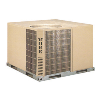
YORK Model B1HA units are factory assembled heat pumps
designed for outdoor installation on a rooftop or a slab. Field-
installed electric heater accessories are available to provide
supplemental electric heat combined with electric cooling and
heating.
The units are completely assembled on rigid, removable
base rails. All piping, refrigerant charge, and electrical wiring
is factory installed and tested. The units require only electric
power and duct connections at the point of installation.
The electric heaters have nickel-chrome resistance wire ele-
ments and utilize single point power connection.
INSPECTION
As soon as a unit is received, it should be inspected for pos-
sible damage during transit. If damage is evident, the extent
of the damage should be noted on the carrier's freight bill. A
separate request for inspection by the carrier's agent should
be made in writing. Refer to Form 50.15-NM for additional in-
formation.
Installer should pay particular attention to the words: NOTE, CAUTION and WARNING. Notes are intended to clarify or
make the installation easier. Cautions are given to prevent equipment damage. Warnings are given to alert installer that per-
sonal injury and/or equipment damage may result if installation procedure is not handled properly.
®
SINGLE PACKAGE HEAT PUMPS
Supersedes: 035-16004-000 (0801)
MODELS B1HA018 THRU 060
1.5 THRU 5 TON
(10 SEER)
CAUTION
THIS PRODUCT M UST BE INSTALLED IN STRICT COMPLIANCE W ITH
THE ENCLOSED INSTALLATION INSTRUCTIONS AND ANY APPLICABLE
LOCAL, STATE, AND NATIONAL CODES INCLUDING, BUT NOT LIMITED
TO, BUILDING, ELECTRICAL, AND MECHANICAL CODES.
WARNING
INCORRECT INSTALLATION MAY CREATE A CONDITION WHERE THE
OPERATION OF THE PRODUCT COULD CAUSE PERSONAL INJURY
O R P R O P E R T Y D A M A G E .
CHAMPION
SERIES
®
REFERENCE
Additional information on the design, installation, operation
and service of this equipment is available in the following refer-
ence forms:
• 55.70-N1
-General Installation
• 55.70-N2
-Pre-start & Post-start Check List
• 511.26-N1.1V -Electric Heater Accessory
RENEWAL PARTS
• Refer to Replacement Parts Manual for complete listing of
replacement parts on this equipment.
All forms referenced in this instruction may be ordered from:
Standard Register
2101 West Techumseh Road
Norman, OK 73069
Toll Free: Tel. 877-318-9675/Fax. 877-379-7920
035-16004-001-A-0202
Advertisement
Table of Contents

Related Manuals for York B1HA018A06


Summary of Contents for York B1HA018A06
-
Page 1: Installation Instruction
(10 SEER) GENERAL REFERENCE YORK Model B1HA units are factory assembled heat pumps Additional information on the design, installation, operation designed for outdoor installation on a rooftop or a slab. Field- and service of this equipment is available in the following refer-... - Page 2 035-16004-001-A-0202 PRODUCT NOMENCLATURE PRODUCT CATEGORY VOLTAGE CODE B = Single Package Heat Pumps 06 = 208/230-1-60 (Air Cooled) 25 = 208/230-3-60 46 = 460-3-60 PRODUCT GENERATION 58 = 575-3-60 NOMINAL COOLING CAPACITY (MBH) 1 = NEW or Current Design FACTORY 018 = 18,000 BTUH 042 = 42,000 BTUH INSTALLED ELECTRIC HEAT 024 = 24,000 BTUH 048 = 48,000 BTUH...
- Page 3 035-16004-001-A-0202 CAUTION: When fastening duct work to the side duct flanges on CLEARANCES the unit, insert the screws through the duct flanges only. All units require certain clearances for proper operation and DO NOT insert the screws through the casing. Outdoor service.
- Page 4 035-16004-001-A-0202 N.E.C./C.E.C. Voltage tolerances which must be maintained SERVICE ACCESS at the compressor terminals during starting and running con- Access to all serviceable components is provided by the follow- ditions are indicated on the unit Rating Plate and Table 3. ing removable panels: •...
- Page 5 035-16004-001-A-0202 TABLE 4 - SIDE AND BOTTOM SUPPLY AIR BLOWER PERFORMANCE 230/460/575 volts EXTERNAL STATIC PRESSURE - IWG 1.00 1.10 MODEL NO. MOTOR SPEED 1200 1100 1200 1134 1068 1002 1414 1317 1219 1116 1013 1472 1394 1297 1199 1102 1462 1400 1337...
- Page 6 035-16004-001-A-0202 TABLE 5 - (HEAT PUMP / ELECTRIC HEAT) ELECTRICAL DATA COMPRESSOR ELECTRIC HEAT ACCESSORY SUPPLY OUTDOOR MAX. MAX. MINIMUM HACR ‚ POWER FUSE BLOWER CIRCUIT SIZE, SUPPLY MOTOR BREAKER MOTOR, AMPACITY AMPS SIZE TOTAL MODEL NO. AMPS 2NH04500506 3.8/5.0 * 18.1/20.8 37.5/41.0...
- Page 7 035-16004-001-A-0202 TABLE 5 - (HEAT PUMP / ELECTRIC HEAT) (Continued) ELECTRICAL DATA COMPRES- SUPPLY ELECTRIC HEAT ACCESSORY OUT- MINIMUM MAX. MAX. DOOR HACR ‚ POWER BLOWE CIRCUIT FUSE SIZE, SUPPLY AMPAC- BREAKER MOTOR MOTOR, AMPS SIZE TOTAL MODEL NO. AMPS 2NH04501058 10.0 ***...
- Page 8 035-16004-001-A-0202 TABLE 6 - ELECTRICAL DATA (BASIC UNIT) VOLTAGE SUPPLY MAX. MAX. OUTDOOR LIMITATIONS COMPRESSOR MINIMUM FUSE HACR UNIT MODEL POWER SUP- TRANSFORMER BLOWER CIRCUIT SIZE, BREAKER POWER MOTOR, SIZE (VA) MOTOR, AMPACITY SIZE, FACTOR AMPS MIN. MAX. AMPS 208/230-1-60 48.0 14.9...
- Page 9 035-16004-001-A-0202 Checking Supply Air CFM curate. To ensure a dry coil, the compressors should be de- activated while the test is being run. To check the supply air CFM after the initial balancing has been completed: 4.Knowing the pressure drop across a dry coil, the actual CFM through the unit can be determined from the curve in 1.Remove the two ¼...
- Page 10 035-16004-001-A-0202 TABLE 7 - COOLING SUPERHEAT AT COMPRESSOR SUCTION, AIRFLOW = 600 CFM (B1HA018) INDOOR WB TEMPERATURE, °F OUTDOOR TEMPERATURE, °F 14.5 19.7 25.0 30.2 35.5 40.8 40.3 39.7 39.2 38.7 14.2 18.8 23.4 28.0 32.5 37.1 37.3 37.5 37.7 37.9 10.1 14.0...
- Page 11 035-16004-001-A-0202 TABLE 9 - COOLING SUPERHEAT AT COMPRESSOR SUCTION, AIRFLOW = 800 CFM (B1HA024) INDOOR WB TEMPERATURE, °F OUTDOOR TEMPERATURE, °F 17.0 18.2 19.4 20.5 21.7 22.8 24.0 27.0 30.0 33.0 36.0 14.3 15.5 16.7 17.8 19.0 20.1 21.3 24.6 27.9 31.1 34.4...
- Page 12 035-16004-001-A-0202 TABLE 13 - COOLING SUPERHEAT AT COMPRESSOR SUCTION, AIRFLOW = 1,200 CFM (B1HA036) INDOOR WB TEMPERATURE, °F OUTDOOR TEMPERATURE, °F 12.8 16.1 19.3 22.5 25.8 29.0 32.2 35.0 37.7 40.4 43.1 11.4 14.3 17.2 20.1 22.9 25.8 28.7 31.6 34.4 37.3 40.1...
- Page 13 035-16004-001-A-0202 TABLE 17 - COOLING SUPERHEAT AT COMPRESSOR SUCTION, AIRFLOW = 1,600 CFM (B1HA048) INDOOR WB TEMPERATURE, °F OUTDOOR TEMPERATURE, °F 11.4 12.4 13.5 14.6 15.7 16.8 17.9 19.3 20.7 22.1 23.5 10.3 11.2 12.2 13.1 14.0 14.9 15.9 17.4 18.9 20.4 21.9...
- Page 14 035-16004-001-A-0202 HIGH VOLTAGE CONN. FRONT COMPRESSOR " DIA. KNOCKOUT & SERVICE ACCESS HIGH VOLTAGE CONN. COMPARTMENT PANEL " DIA. KNOCKOUT DIMENSION LOW VOLTAGE CONN. “A” UNIT SIZE “A” “ DIA. KNOCKOUT & (OVERALL) & 018 - 042 048 - 060 SIDE SUPPLY AIR OPENING REFRIGERANT...
-
Page 15: Sequence Of Operation
035-16004-001-A-0202 SEQUENCE OF OPERATION Anti-short Cycle Timer stat is in the “ON” position, the indoor blower will continue to This unit has an anti-short cycle timer built in to the defrost con- run. If the fan switch is in the “AUTO” position, the “K1" relay trol. - Page 16 035-16004-001-A-0202 TABLE 21 - THERMOSTAT SIGNALS (SINGLE PHASE UNITS) SIGNAL STATE BOARD FUNCTION FAN INSTANT ON “G” FAN INSTANT OFF FAN INSTANT ON COMPRESSOR AND OUTDOOR FAN INSTANT ON (AFTER ANTI-SHORT CYCLE DELAY) REVERSING VALVE ENERGIZED “G” & “Y” & “O” SYSTEM OPERATES IN COOLING COMPRESSOR AND OUTDOOR FAN INSTANT OFF FAN 60 SEC.
- Page 17 035-16004-001-A-0202 TABLE 22 - THERMOSTAT SIGNALS (THREE PHASE UNITS) SIGNAL STATE BOARD FUNCTION FAN INSTANT ON “G” FAN INSTANT OFF FAN INSTANT ON COMPRESSOR AND OUTDOOR FAN INSTANT ON (AFTER ANTI-SHORT CYCLE DELAY) REVERSING VALVE ENERGIZED “G” & “Y” & “O” SYSTEM OPERATES IN COOLING COMPRESSOR AND OUTDOOR FAN INSTANT OFF FAN 60 SEC.
- Page 18 035-16004-001-A-0202 FOR DUAL POINT FOR DUAL POINT ELECTRIC HEAT ELECTRIC HEAT POWER SUPPLY POWER SUPPLY SEE DETAIL A SEE DETAIL A DETAIL "B" FOR DEFROST CONTROL 031-09104-000A SEE DETAIL C DEFROST CONTROL 031-01268-000B OPTIONAL CCH DETAIL C SECONDARY POWER SUPPLY SECONDARY POWER SUPPLY FOR DUAL POINT ELEC HEAT FOR DUAL POINT ELEC HEAT...
- Page 19 035-16004-001-A-0202 DETAIL A COMPR RELAY 222/Y DFST STAT FOR DEFROST CONTROL 031-09104-000A DEFROST SEE DETAIL A CONTROL 031-01268-000B FIG. 5 - TYPICAL WIRING DIAGRAM (230-3-60 POWER SUPPLY) Unitary Products Group...
- Page 20 035-16004-001-A-0202 E L E M E N T A R Y D I A G R A M P O W E R S U P P L Y W / O U T E L E C H E A T 4 6 0 - 3 - 6 0 O R 5 7 5 - 3 - 6 0 G N D U S E C O P P E R...
- Page 21 035-16004-001-A-0202 TYPICAL WIRING DIAGRAM LEGEND (See page 16, 17 and 18) CIRCUIT BREAKER 24V, 3 AMP , 20, & 25 , 20, & 25 F7 F8 F9 20 & 25 ALL KW ELEC HEAT) , 20, & 25 20 & 25 KW ELEC HEAT) HTR 4 ELECTRIC HEATER (OPT.
- Page 22 035-16004-001-A-0202 Unitary Products Group...
- Page 23 035-16004-001-A-0202 Unitary Products Group...
- Page 24 035-16004-001-A-0202 Unitary Products Group 5005 York Drive, Norman, Oklahoma 73069 Subject to change without notice. Printed in U.S.A. 035-16004-001-A-0202 Copyright by York International Corporation 2000. All Rights Reserved. Supersedes: 035-16004-000-0801...