
Related Manuals for Yamaha Super Tenere XTZ12H 2016


Summary of Contents for Yamaha Super Tenere XTZ12H 2016
- Page 1 Read this manual carefully before operating this vehicle. OWNER’S MANUAL XTZ12H 2BS-28199-73...
- Page 2 EAU46091 Read this manual carefully before operating this vehicle. This manual should stay with this vehicle if it is sold.
- Page 3 Introduction EAU45931 Congratulations on your purchase of the Yamaha XTZ12H. This model is the result of Yamaha’s vast experience in the pro- duction of fine sporting, touring, and pacesetting racing machines. It represents the high degree of craftsmanship and re- liability that have made Yamaha a leader in these fields.
-
Page 4: Important Manual Information
Important manual information EAU10134 Particularly important information is distinguished in this manual by the following notations: This is the safety alert symbol. It is used to alert you to potential personal injury hazards. Obey all safety messages that follow this symbol to avoid possible injury or death. - Page 5 Important manual information EAU10201 XTZ12H OWNER’S MANUAL ©2016 by Yamaha Motor Co., Ltd. 1st edition, August 2016 All rights reserved. Any reprinting or unauthorized use without the written permission of Yamaha Motor Co., Ltd. is expressly prohibited. Printed in Japan.
-
Page 6: Table Of Contents
Table of contents Location of important labels... 1-1 Windshield ........4-33 Coolant ......... 7-17 Adjusting the front fork ....4-34 Air filter element......7-18 Safety information......2-1 Adjusting the shock absorber Checking the engine idling assembly........4-36 speed ........7-18 Description ........3-1 Carriers..........4-38 Checking the throttle grip free Left view ......... - Page 7 Troubleshooting ......7-37 Troubleshooting charts ....7-38 Motorcycle care and storage ..8-1 Matte color caution ......8-1 Care ..........8-1 Storage ..........8-4 Specifications........9-1 Consumer information ....10-1 Identification numbers....10-1 Diagnostic connector ....10-3 Maintenance record ......10-4 YAMAHA MOTOR CANADA LTD. MOTORCYCLE WARRANTY GUIDE ........10-6 Index ..........11-1...
-
Page 8: Location Of Important Labels
Read and understand all of the labels on your vehicle. They contain important information for safe and proper operation of your vehicle. Never remove any labels from your vehicle. If a label becomes difficult to read or comes off, a replacement label is available from your Yamaha dealer. 10 9... - Page 9 Location of important labels WARNING AVERTISSEMENT Improper loading can cause loss Un chargement incorrect risque de causer of control. une perte de contrôle. NEVER sit on the carrier. NE JAMAIS s’asseoir sur le porte-bagages. Refer to instructions in the Owner’s Se reporter aux instructions données dans Manual.
- Page 10 Location of important labels WARNING ATTENTION NOTICE Eviter de nettoyer le Cleaning with alkaline or BEFORE YOU OPERATE THIS VEHICLE, READ pare-brise avec une solution acid cleaner, gasoline or THE OWNER’S MANUAL AND ALL LABELS. alcaline ou acide ainsi solvent will damage qu’avec de l’essence ou ALWAYS WEAR AN APPROVED MOTORCYCLE windshield.
- Page 11 Location of important labels WARNING AVERTISSEMENT NEVER ride as a passenger AUCUN passager ne doit rouler if the passenger seat quand la selle du passager et and grips are removed. les poignées sont déposées. 23P-2816J-20...
-
Page 12: Safety Information
Safety information Never operate a motorcycle with- pears to be very effective in reduc- EAU1031C out proper training or instruction. ing the chance of this type of Take a training course. Beginners accident. Be a Responsible Owner should receive training from a cer- Therefore: As the vehicle’s owner, you are re- tified instructor. - Page 13 Safety information Many accidents involve inexperi- Wear a face shield or goggles. • Always signal before turning or enced operators. In fact, many op- changing lanes. Make sure that Wind in your unprotected eyes erators who have been involved in other motorists can see you.
- Page 14 Safety information Carbon Monoxide is a colorless, odor- Loading close to the center of the vehicle less, tasteless gas which may be pres- Adding accessories or cargo to your as possible and make sure to dis- ent even if you do not see or smell any motorcycle can adversely affect stabil- tribute the weight as evenly as engine exhaust.
- Page 15 Yamaha accessories, which are avail- characteristics can put you and others • Bulky or large accessories may able only from a Yamaha dealer, have at greater risk of serious injury or seriously affect the stability of been designed, tested, and approved death.
- Page 16 Safety information Secure the motorcycle with tie- Aftermarket Tires and Rims The tires and rims that came with your downs or suitable straps that are motorcycle were designed to match attached to solid parts of the mo- the performance capabilities and to torcycle, such as the frame or up- provide the best combination of han- per front fork triple clamp (and not,...
-
Page 17: Description
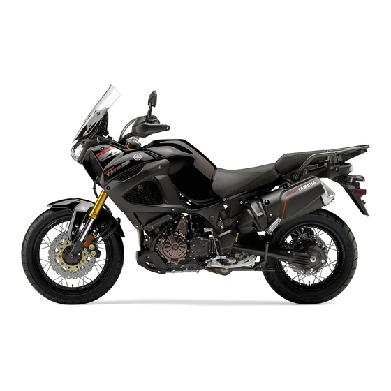
Description EAU10411 Left view 1. Fuel tank cap (page 4-28) 9. Engine oil drain bolt (crankcase) (page 7-12) 2. Seat lock (page 4-31) 10.Engine oil filter cartridge (page 7-12) 3. Carrier (page 4-38) 4. Final gear oil filler bolt (page 7-15) 5. -
Page 18: Right View
Description EAU10421 Right view 1. Rear brake fluid reservoir (page 7-24) 9. Engine oil filler cap (page 7-12) 2. Shock absorber assembly spring preload adjusting knob (page 4-36) 10.Engine oil level check window (page 7-12) 3. Front fork rebound damping force adjusting screw (page 4-34) 11.Brake pedal (page 4-25) 4. -
Page 19: Controls And Instruments
Description EAU10431 Controls and instruments 1. Clutch lever (page 4-23) 9. Throttle grip (page 7-19) 2. Left handlebar switches (page 4-21) 10.Main switch/steering lock (page 4-2) 3. Clutch fluid reservoir (page 7-24) 4. Multi-function meter unit (page 4-9) 5. Auxiliary DC jack (page 4-41) 6. -
Page 20: Instrument And Control Functions
Do not place any key close to three keys to a Yamaha dealer to have Operation is subject to the following them re-registered. Do not use the key magnets (this includes, but not two conditions: with the red bow for driving. -
Page 21: Main Switch/Steering Lock
Instrument and control functions Do not put two keys of any im- position lights come on, and the engine EAU10474 Main switch/steering lock mobilizer system on the same can be started. The key cannot be re- moved. key ring. ... -
Page 22: Indicator Lights And Warning
Instrument and control functions To lock the steering To unlock the steering EAU4939B Indicator lights and warning lights GEAR A.TEMP ˚C C.TEMP ˚C TIME TRIP 0:00 1. Push. 1. Push. 2. Turn. 2. Turn. 1. Left turn signal indicator light “ ”... - Page 23 The electrical circuit of these indicator EAU11032 Turn signal indicator lights “ ” (see page 7-12), have a Yamaha dealer lights can be checked by turning the and “ ” check the vehicle.
- Page 24 If the light does not come on initially warning light comes on or flashes when the key is turned to “ON”, or if the light remains on, have a Yamaha dealer while riding, the brake system re- The engine trouble warning light will check the electrical circuit.
-
Page 25: Cruise Control System
“ON”, traffic, poor weather conditions, or if the indicator light remains on, have or among winding, slippery, a Yamaha dealer check the electrical hilly, rough or gravel roads. circuit. When traveling uphill or down-... - Page 26 Instrument and control functions Activating and setting the cruise cruise control setting switch down will control system increase or decrease the speed contin- 1. Push the cruise control power uously until the switch is released. switch “ ” located on the left You can also manually increase your handlebar.
- Page 27 Instrument and control functions speed will return to the previously set Automatic deactivation of the cruise stalls, or the sidestand is lowered, then cruising speed. The “SET” indicator control system the “ ” indicator light will go off (the light will come on. The cruise control system for this mod- “SET”...
-
Page 28: Multi-Function Meter Unit
C.TEMP ˚C GEAR light will flash. If this occurs, turn the TIME TRIP 0:00 cruise control system off and have a A.TEMP ˚C Yamaha dealer check it. C.TEMP ˚C TIME TRIP 0:00 ECA11591 NOTICE 1. “RESET” button 2. “TCS” button If the display indicates an error co- 3. - Page 29 Instrument and control functions settings while riding can distract the Tachometer operator and increase the risk of an accident. multi-function meter unit equipped with: speedometer tachometer clock fuel meter eco indicator 1. Menu switch “MENU” ...
- Page 30 Travel at a constant speed. fuel meter will start flashing. If this oc- Select the transmission gear that curs, have a Yamaha dealer check the vehicle. is appropriate for the vehicle speed. 4-11...
- Page 31 Instrument and control functions Drive mode indicator Traction control system indicator Information display GEAR TRIP-1 TRIP-2 GEAR GEAR A.TEMP ˚C RANGE C.TEMP ˚C FUEL AVG km/L 12.3 TIME TRIP CRNT FUEL km/L 0:06 12.3 1. Drive mode indicator 1. Traction control system indicator 1.
- Page 32 Instrument and control functions average fuel consumption The tripmeters will reset and con- TRIP-F → Display–1 → Display–2 → Display–3 → TRIP-F instantaneous fuel consumption tinue counting after 9999.9 is reached. Odometer: To reset a tripmeter, push the “RESET” The fuel reserve tripmeter shows the button briefly so that the tripmeter distance traveled on the fuel reserve.
- Page 33 Instrument and control functions The temperature reading may be This timer shows the elapsed time since the key was turned to “ON”. The affected by engine heat when rid- The information display pages cannot maximum time that can be shown is ing slowly (under 20 km/h [12 be rotated when the engine overheat 99:59.
- Page 34 Have a If there is a malfunction, “– –.–” will mode. Yamaha dealer check the vehicle. be continuously displayed. Have a Shifting the transmission into gear Yamaha dealer check the vehicle.
- Page 35 Instrument and control functions and return to the normal display, push 3. While the selected item is flashing, Reset all items, except the All Reset odometer and the clock. and hold the menu switch “MENU” push and hold the “RESET” but- again for 2 seconds.
- Page 36 Instrument and control functions 2. Push the menu switch “MENU”. 4. Use select switch The unit setting display will be highlight “ ”, and then push the Time Trip shown and “km/L or L/100km” will menu switch “MENU” to return to flash in the display.
- Page 37 Instrument and control functions 2. Push the menu switch “MENU”, 4. Use the select switch to select the use the select switch to highlight item that you want to appear, and Display-1 the page you want to adjust, and then push the menu switch then push the menu switch “MENU”...
- Page 38 Instrument and control functions 2. Push the menu switch “MENU”. 2. Push the menu switch “MENU”. 3. Use the select switch to select the 3. When the hour digits start flash- MENU desired brightness level, and then ing, use the select switch to set Maintenance push the menu switch “MENU”...
- Page 39 If this occurs, note the code number and 2. If the engine starts, turn it off, and have a Yamaha dealer check the vehi- try starting the engine with the cle. standard keys.
-
Page 40: D-Mode (Drive Mode)
Instrument and control functions This mode allows the rider to enjoy EAU49433 EAU1234M D-mode (drive mode) Handlebar switches smooth drivability from the low-speed D-mode is an electronically controlled range to the high-speed range. Left engine performance system with two mode selections (touring mode “T” and Sports mode “S”... - Page 41 Instrument and control functions Right ter position. To cancel the turn signal EAU12735 Hazard switch “ ” lights, push the switch in after it has re- With the key in the “ON” or “ ” posi- turned to the center position. tion, use this switch to turn on the haz- ard lights (simultaneous flashing of all EAU12501...
-
Page 42: Clutch Lever
Instrument and control functions Make sure that the appropriate setting EAU59001 EAU12832 Select switch “ ” Clutch lever on the adjusting dial is aligned with the This switch is used to perform selec- arrow mark on the clutch lever. tions in the information display and The clutch lever is equipped with a setting mode display of the multi-func- clutch switch, which is part of the igni-... -
Page 43: Shift Pedal
Instrument and control functions After coming to a stop while ap- EAU12872 EAU49518 Shift pedal Brake lever plying the brake lever, the unified The brake lever is located on the right brake system is still enabled. As side of the handlebar. To apply the further squeezing of the brake le- front brake, pull the lever toward the ver will not increase the braking... -
Page 44: Brake Pedal
Make sure that the appropriate setting EAU49483 EAU54532 Brake pedal on the adjusting dial is aligned with The Yamaha ABS (Anti-lock Brake the “ ” mark on the brake lever. System) features a dual electronic con- trol system, which acts on the front and rear brakes independently. -
Page 45: Traction Control System
ABS is op- the traction control system is engaged. erating. However, special tools are required, so please consult your EWA15432 WARNING Yamaha dealer. The traction control system is not a ECA16831 NOTICE substitute for riding appropriately for the conditions. Traction control... - Page 46 Instrument and control functions ping. As with any motorcycle, ap- OFF” and turn the traction control sys- proach surfaces that tem off. Push the button again to return Use the mode “TCS OFF” to help free to the previously selected mode “1” or slippery with caution and avoid es- the rear wheel if the motorcycle gets pecially slippery surfaces.
-
Page 47: Fuel Tank Cap
1/4 turn clockwise. The lock will be still be ridden; however, have a released and the fuel tank cap can be Yamaha dealer check the motorcycle opened. as soon as possible. To close the fuel tank cap 1. -
Page 48: Fuel
WARNING pump nozzle into the fuel tank filler Gasoline is poisonous and can cau- Your Yamaha engine has been de- hole. Stop filling when the fuel se injury or death. Handle gasoline signed to use premium unleaded gas- reaches the bottom of the filler with care. -
Page 49: Fuel Tank Breather Hose And Overflow Hose
10% (E10). Gas- Do not park the vehicle near ohol containing methanol is not possible fire hazards such as recommended by Yamaha because it grass or other materials that can cause damage to the fuel system easily burn. -
Page 50: Rider Seat
Instrument and control functions ECA10702 EAU49444 Rider seat NOTICE Use only unleaded gasoline. The use To remove the rider seat of leaded gasoline will cause unre- 1. Insert the key into the seat lock, pairable damage to the catalytic and then turn it counterclockwise. converter. -
Page 51: Adjusting The Rider Seat Height
Instrument and control functions 4. Insert the projection on the rear of EAU49475 Adjusting the rider seat height the rider seat into seat holder A as The rider seat height can be adjusted shown. to one of two positions to suit the rid- er’s preference. -
Page 52: Windshield
Instrument and control functions 4. Insert the projection on the rear of EAU58982 Windshield the rider seat into seat holder B as To suit the rider’s preference, the wind- shown. shield can be changed to one of four positions. To adjust the windshield height 1. -
Page 53: Adjusting The Front Fork
Instrument and control functions EAU59140 Adjusting the front fork EWA10181 WARNING Always adjust both fork legs equally, otherwise poor handling and loss of stability may result. This front fork is equipped with spring preload adjusting bolts, rebound damping force adjusting screws and 1. - Page 54 Instrument and control functions Spring preload setting: Rebound damping setting: Minimum (soft): Minimum (soft): Distance A = 19.0 mm (0.75 in) 10 click(s) in direction (b)* Standard: Standard: Distance A = 14.0 mm (0.55 in) 8 click(s) in direction (b)* Maximum (hard): Maximum (hard): Distance A = 4.0 mm (0.16 in)
-
Page 55: Adjusting The Shock Absorber Assembly
Instrument and control functions justment, it would be advisable to EAU49692 Adjusting the shock absorber check the number of clicks of each assembly damping force adjusting mechanism This shock absorber assembly is and to modify the specifications as equipped with a spring preload adjust- necessary. - Page 56 Take the shock ce and thereby harden the rebound advisable to check the actual total absorber assembly to a Yamaha damping, turn the adjusting knob in di- number of clicks or turns of each dealer for any service.
-
Page 57: Carriers
This additional carrier extends the loading surface and the loading ca- pacity of the standard carrier. To use the additional carrier, consult a Yamaha dealer. 1. Additional carrier Standard carrier 1. Luggage strap holder EWA15482... -
Page 58: Sidestand
EAU15306 EAU54491 Sidestand Ignition circuit cut-off system Yamaha dealer repair it if it does not The sidestand is located on the left The ignition circuit cut-off system function properly. side of the frame. Raise the sidestand... - Page 59 ”. stand during this inspection. • 3. Turn the key on. If a malfunction is noted, have a Yamaha 4. Shift the transmission into the neutral position. dealer check the system before riding. 5. Push the “ ” side of the start/engine stop switch.
-
Page 60: Auxiliary Dc Jack
Instrument and control functions EAU49453 Auxiliary DC jack EWA14361 WARNING To prevent electrical shock or short- circuiting, make sure that the cap is installed when the auxiliary DC jack is not being used. ECA15432 NOTICE 1. Auxiliary DC jack cap The accessory connected to the 3. -
Page 61: For Your Safety - Pre-Operation Checks
• If necessary, add recommended coolant to specified level. 7-17 • Check cooling system for leakage. • Check operation. • If soft or spongy, have Yamaha dealer bleed hydraulic system. • Check brake pads for wear. Front brake • Replace if necessary. - Page 62 • Make sure that operation is smooth. • Check throttle grip free play. Throttle grip 7-19, 7-26 • If necessary, have Yamaha dealer adjust throttle grip free play and lubricate ca- ble and grip housing. • Check for damage. • Check tire condition and tread depth.
-
Page 63: Operation And Important Riding Points
a lean angle sensor to stop the en- The transmission is in the neutral understand, ask your Yamaha dealer. gine in case of a turnover. In this EWA10272 position. -
Page 64: Shifting
If not, repeatedly until it reaches the end of its ask a Yamaha dealer to check the travel, and then slightly raise it. electrical circuit. 3. Start the engine by pushing the “... - Page 65 Operation and important riding points 4. At the recommended shift points clutch lever in, use the brakes to ECA10261 NOTICE shown in the following table, close slow the motorcycle, and continue Even with the transmission in the throttle, and at the same time, to downshift as necessary.
-
Page 66: Engine Break-In
4th → 3rd: 25 km/h (16 mph) period, immediately have a might result in engine overheating Yamaha dealer check the vehi- must be avoided. cle. EAU58990 0–1000 km (0–600 mi) Avoid prolonged operation above 3900 r/min. -
Page 67: Parking
Operation and important riding points EAU17214 Parking When parking, stop the engine, and then remove the key from the main switch. EWA10312 WARNING Since the engine and exhaust system can become very hot, park in a place where pedestri- ans or children are not likely to touch them and be burned. -
Page 68: Periodic Maintenance And Adjustment
To avoid possible burns, let tivities incorrectly may increase brake components cool before your risk of injury or death during touching them. service or while using the vehicle. If you are not familiar with vehicle ser- vice, have a Yamaha dealer perform service. -
Page 69: Owner's Tool Kit
If you do not have the tools or experi- ence required for a particular job, have 1. Owner’s tool kit a Yamaha dealer perform it for you. The owner’s tool kit is located behind cowling A. (See page 7-9.) To access the owner’s tool kit, remove cowling A with the hexagon wrench, lo- cated on the bottom of the rider seat. -
Page 70: Periodic Maintenance Chart For The Emission Control System
From 37000 km (24000 mi) or 36 months, repeat the maintenance intervals starting from 13000 km (8000 mi) or 12 months. Items marked with an asterisk require special tools, data and technical skills, have a Yamaha dealer perform the ser- vice. -
Page 71: General Maintenance And Lubrication Chart
• Perform dynamic inspection us- Diagnostic system √ √ √ √ √ √ ing Yamaha diagnostic tool. check • Check the error codes. Air filter element • Replace. Every 37000 km (24000 mi) • Check operation, fluid level, and √... - Page 72 Periodic maintenance and adjustment INITIAL ODOMETER READINGS 1000 km 7000 km 13000 km 19000 km 25000 km 31000 km ITEM ROUTINE (600 mi) (4000 mi) (8000 mi) (12000 mi) (16000 mi) (20000 mi) 1 month 6 months 12 months 18 months 24 months 30 months •...
- Page 73 Periodic maintenance and adjustment INITIAL ODOMETER READINGS 1000 km 7000 km 13000 km 19000 km 25000 km 31000 km ITEM ROUTINE (600 mi) (4000 mi) (8000 mi) (12000 mi) (16000 mi) (20000 mi) 1 month 6 months 12 months 18 months 24 months 30 months Shift pedal pivot...
- Page 74 Periodic maintenance and adjustment INITIAL ODOMETER READINGS 1000 km 7000 km 13000 km 19000 km 25000 km 31000 km ITEM ROUTINE (600 mi) (4000 mi) (8000 mi) (12000 mi) (16000 mi) (20000 mi) 1 month 6 months 12 months 18 months 24 months 30 months •...
- Page 75 Periodic maintenance and adjustment • Replace the oil seals on the inner parts of the brake or clutch master cylinders, caliper cylinders and clutch release cylinder every two years. • Replace the brake and clutch hoses every four years or if cracked or damaged.
-
Page 76: Removing And Installing Cowlings
Periodic maintenance and adjustment EAU18782 Removing and installing cowl- ings The cowlings shown need to be re- moved to perform some of the mainte- nance jobs described in this chapter. Refer to this section each time a cowl- ing needs to be removed and installed. 1. - Page 77 Periodic maintenance and adjustment 2. Install the quick fastener screws. Cowling B To remove the cowling 1. Remove cowling A. 2. Remove the bolts and the quick fasteners, and then pull the cowl- ing off. 1. Quick fastener 1. Cowling C 2.
-
Page 78: Checking The Spark Plugs
Before installing a spark plug, the checked periodically, preferably by a spark plug gap should be measured Yamaha dealer. Since heat and depos- with a wire thickness gauge and, if its will cause any spark plug to slowly necessary, adjusted to specification. -
Page 79: Engine Oil And Oil Filter Cartridge
Periodic maintenance and adjustment EAU49506 Engine oil and oil filter car- If a torque wrench is not available tridge when installing a spark plug, a good The engine oil level should be checked estimate of the correct torque is 1/4– before each ride. - Page 80 An oil filter wrench is available at a 4. Remove the engine oil filler cap, Yamaha dealer. the drain bolt and its gasket to 9. Apply a thin coat of clean engine drain the oil from the oil tank.
- Page 81 Periodic maintenance and adjustment Recommended engine oil: See page 9-1. Oil quantity: Oil change: 3.10 L (3.28 US qt, 2.73 Imp.qt) With oil filter removal: 3.40 L (3.59 US qt, 2.99 Imp.qt) Be sure to wipe off spilled oil on any 1.
-
Page 82: Final Gear Oil
If the oil level warning light flickers for oil leakage before each ride. If any or remains on even if the oil level is leakage is found, have a Yamaha deal- correct, immediately turn the engine er check and repair the vehicle. In ad-... - Page 83 2. Place an oil pan under the final Recommended final gear oil: gear case to collect the used oil. Yamaha genuine shaft drive gear oil 3. Remove the final gear oil filler bolt, SAE 80W-90 API GL-5 or SAE 80...
-
Page 84: Coolant
If water has been The coolant should be between the mi- added to the coolant, have a nimum and maximum level marks. Yamaha dealer check the anti- freeze content of the coolant as 7-17... -
Page 85: Air Filter Element
Check the engine idling speed and, if maintenance and lubrication chart. necessary, have it corrected by a Coolant reservoir capacity (up to Have a Yamaha dealer replace the air the maximum level mark): Yamaha dealer. 0.26 L (0.27 US qt, 0.23 Imp.qt) filter element. -
Page 86: Checking The Throttle Grip Free Play
Therefore, it must be adjusted by a Yamaha dealer is essential to maintain the tires in good at the intervals specified in the periodic condition at all times and replace them maintenance and lubrication chart. - Page 87 * Total weight of rider, passenger, car- or glass fragments in it, or if the side- surface must first be “broken go and accessories wall is cracked, have a Yamaha dealer in” for it to develop its optimal replace the tire immediately. characteristics.
- Page 88 1. Tire air valve ed below have been approved for this atively poor grip on certain road 2. Tire air valve core model by Yamaha. surfaces until they have been 3. Tire air valve cap with seal “broken in”. Therefore, it is ad-...
-
Page 89: Spoke Wheels
If any damage is poor acceleration, there may be air in found, have a Yamaha dealer re- the clutch system. If there is air in the place the wheel. Do not attempt hydraulic system, have a Yamaha deal- 1. -
Page 90: Brake Light Switches
Since the brake light ified in the periodic maintenance and switches are components of the cruise lubrication chart. control system, they must be adjusted by a Yamaha dealer, who has the nec- EAU36891 Front brake pads essary professional knowledge and ex- perience. -
Page 91: Checking The Brake Fluid Level
Rear brake EAU40262 Checking the brake fluid level Yamaha dealer replace the brake pads Before riding, check that the brake fluid as a set. is above the minimum level mark. Check the brake fluid level with the top... -
Page 92: Changing The Brake And Clutch Fluids
Use only the specified brake flu- fluid level goes down suddenly, have a EAU22754 Changing the brake and id; otherwise, the rubber seals Yamaha dealer check the cause before clutch fluids further riding. may deteriorate, causing leak- Have a Yamaha dealer change the age. -
Page 93: Checking And Lubricating The Throttle Grip And Cable
In pedals should be checked before each addition, the cable should be lubricat- ride, and the pedal pivots should be lu- ed by a Yamaha dealer at the intervals bricated if necessary. specified in the periodic maintenance Brake pedal chart. -
Page 94: Checking And Lubricating The Brake And Clutch Levers
Clutch lever WARNING If the centerstand or sidestand does not move up and down smoothly, have a Yamaha dealer check or re- pair it. Otherwise, the centerstand or sidestand could contact the ground and distract the operator, resulting in a possible loss of control. -
Page 95: Lubricating The Swingarm Pivots
1. Place the vehicle on a level surfa- The swingarm pivots must be lubricat- ce and hold it in an upright posi- ed by a Yamaha dealer at the intervals tion. WARNING! To avoid injury, specified in the periodic maintenance securely support the vehicle so and lubrication chart. -
Page 96: Checking The Steering
Yamaha dealer check or re- tion chart. If there is play in the wheel ward and backward. If any free pair it. -
Page 97: Battery
To charge the battery Electrolyte is poisonous and ge it if necessary. Have a Yamaha dealer charge the bat- 3. Fully charge the battery before dangerous since it contains sul- installation. NOTICE: When in-... -
Page 98: Replacing The Fuses
Periodic maintenance and adjustment key is turned to “OFF”, then EAU58963 Replacing the fuses connect the positive lead before The fuse boxes and the ABS motor connecting the negative lead. fuse are located behind cowling A, and [ECA16841] the main fuse, the cruise control fuse 4. - Page 99 50.0 A Terminal fuse 1: age to the electrical system and 4. If the fuse immediately blows 3.0 A possibly a fire. again, have a Yamaha dealer [EWA15132] Headlight fuse: check the electrical system. 20.0 A Brake light fuse: 1.0 A Parking lighting fuse: 7.5 A...
-
Page 100: Replacing A Headlight Bulb
5. Connect the headlight coupler. 6. Install the headlight bulb cover by turning it clockwise. 7. Have a Yamaha dealer adjust the headlight beam if necessary. 1. Headlight coupler 3. Unhook the headlight bulb holder, and then remove the burnt-out bulb. -
Page 101: Replacing An Auxiliary Light Bulb
Periodic maintenance and adjustment EAU58971 Replacing an auxiliary light bulb This model is equipped with two auxil- iary lights. If an auxiliary light bulb burns out, replace it as follows. 1. Remove the windshield by remov- ing the screws. 1. Cover 1. - Page 102 Periodic maintenance and adjustment 1. Headlight lead 1. Auxiliary light bulb 14. Install the windshield by installing the screws, and then tightening 6. Remove the auxiliary light bulb 8. Insert a new bulb into the socket. them to the specified torque. socket (together with the bulb) by 9.
-
Page 103: Turn Signal Light And Brake/Tail Light
If a turn signal light or the brake/tail light does not come on, have a Yamaha dealer check it. 1. License plate light bulb socket 3. Remove the burnt-out bulb by pulling it out. 1. License plate light unit 2. -
Page 104: Troubleshooting
The following troubleshooting charts represent quick and easy procedures for checking these vital systems your- self. However, should your motorcycle require any repair, take it to a Yamaha dealer, whose skilled technicians have the necessary tools, experience, and know-how to service the motorcycle properly. -
Page 105: Troubleshooting Charts
Remove the spark plugs and check the electrodes. The engine does not start. Have a Yamaha dealer check the vehicle. Check the compression. 4. Compression The engine does not start. There is compression. - Page 106 Start the engine. If the engine overheats again, have a The coolant level Yamaha dealer check and repair the cooling system. is OK. If coolant is not available, tap water can be temporarily used instead, provided that it is changed to the recommended cool- ant as soon as possible.
-
Page 107: Motorcycle Care And Storage
Be ble. Rust and corrosion can develop ECA10773 NOTICE sure to consult a Yamaha dealer for even if high-quality components are used. A rusty exhaust pipe may go un- advice on what products to use be- ... - Page 108 For in combination with water, carry out a windshield: Do not use strong additional cleaning, use Yamaha Wind- the following steps after each ride in cleaners or hard sponges as shield Cleaner or other quality cleaner.
- Page 109 Before using them, make a EWA11132 WARNING test by polishing an area which does Consult a Yamaha dealer for ad- not affect your visibility. Contaminants on the brakes or tires vice on what products to use. can cause loss of control.
-
Page 110: Storage
Motorcycle care and storage 2. Fill up the fuel tank and add fuel e. Remove the spark plug caps EAU49592 Storage stabilizer (if available) to prevent from the spark plugs, and then the fuel tank from rusting and the install the spark plugs and the Short-term fuel from deteriorating. - Page 111 Motorcycle care and storage Make any necessary repairs before storing the motorcycle.
-
Page 112: Specifications
Final gear oil: 11.0 : 1 Overall length: Type: Starting system: 2255 mm (88.8 in) Yamaha genuine shaft drive gear oil SAE Electric starter Overall width: 80W-90 API GL-5 or SAE 80 API GL-4 Lubrication system: 980 mm (38.6 in) - Page 113 Specifications Clutch: Front tire: Rim size: 19M/C x MT2.50 Clutch type: Type: Rear wheel: Wet, multiple-disc Tubeless Drivetrain: Size: Wheel type: 110/80R19M/C 59V Spoke wheel Primary reduction ratio: Manufacturer/model: Rim size: 1.466 (85/58) BRIDGESTONE/BW-501 17M/C x MT4.00 Final drive: Rear tire: Unified brake system: Shaft Secondary reduction ratio:...
- Page 114 Specifications Shock absorber: Neutral indicator light: Parking lighting fuse: Gas-hydraulic damper 7.5 A Wheel travel: High beam indicator light: Radiator fan motor fuse: 190 mm (7.5 in) 20.0 A Electrical system: Oil level warning light: Fuel injection system fuse: 20.0 A System voltage: Turn signal indicator light: ABS control unit fuse:...
-
Page 115: Consumer Information
Vehicle identification number ed when registering the vehicle with the authorities in your area and when EAU26442 Engine serial number ordering spare parts from a Yamaha dealer. VEHICLE IDENTIFICATION NUMBER: 1. Vehicle identification number ENGINE SERIAL NUMBER: The vehicle identification number is 1. - Page 116 Yamaha dealer. required by federal law, state law and key. Environment Canada.
-
Page 117: Diagnostic Connector
Consumer information EAU69910 Diagnostic connector 1. Diagnostic connector The diagnostic connector is located as shown. 10-3... -
Page 118: Maintenance Record
Consumer information EAU26643 Maintenance record Copies of work orders and/or receipts for parts purchased and installed on your vehicle will be required to document that maintenance has been completed in accordance with the emissions warranty. The chart below is printed only as a reminder that maintenance work is required. - Page 119 Consumer information Maintenance Date of Servicing dealer Mileage Remarks interval service name and address 55000 km (36000 mi) or 54 months 61000 km (40000 mi) or 60 months 10-5...
-
Page 120: Yamaha Motor Canada Ltd
In this warranty, the term ‘MOTORCYCLE’ shall refer to a new or YZ, with the exception of WR25R, WR25X and YZ85 change of registration is sent to YAMAHA at the time of such motorcycle manufactured by YAMAHA MOTOR COMPANY, LTD. - Page 121 CUSTOMER at the time of DELIVERY. fitness for a particular purpose on the part of YAMAHA, and any other obligation or liability on behalf of YAMAHA, and the above...
-
Page 122: Index
Index ABS............4-25 Engine break-in ........6-4 Main switch/steering lock .......4-2 ABS warning light ........4-5 Engine idling speed, checking ..... 7-18 Maintenance and lubrication, periodic..7-4 Air filter element ........7-18 Engine oil and oil filter cartridge ... 7-12 Maintenance, emission control Auxiliary DC jack........4-41 Engine serial number...... - Page 123 Index Throttle grip and cable, checking and lubricating........... 7-26 Throttle grip free play, checking... 7-19 Tires ............7-19 Tool kit............ 7-2 Traction control system......4-26 Traction control system indicator/warning light......4-5 Troubleshooting........7-37 Troubleshooting charts......7-38 Turn signal indicator lights ..... 4-4 Turn signal light and brake/tail light ..
- Page 125 Yamalube – Take care of your Yamaha with legendary Yamalube oils, lubricants, and care products. They’re formulated and approved by the toughest judges we know: the Yamaha engineering teams that know your Yamaha from the inside out.
- Page 126 PRINTED ON RECYCLED PAPER PRINTED IN JAPAN 2016.10-0.3×1 CR...