Table of Contents
Advertisement
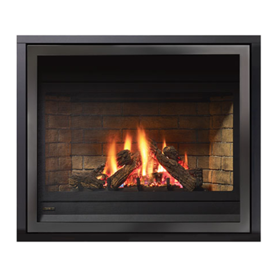
Panorama
WARNING
FIRE OR EXPLOSION HAZARD
Failure to follow safety warnings exactly could result in serious
injury, death, or property damage.
- Do not store or use gasoline or other flammable vapors and liquids in the vicinity of this or any other
appliance.
- WHAT TO DO IF YOU SMELL GAS
•
Do not try to light any appliance.
• Do not touch any electrical switch: do not use any phone in your building.
Leave the building immediately.
• Immediately call your gas supplier from a neighbour's phone. Follow the gas supplier's
instructions.
• If you cannot reach you gas supplier, call the fire department.
- Installation and service must be performed by a qualified installer, service agency or the gas supplier.
Tested by:
919-470e
REGENCY FIREPLACE PRODUCTS INTERNATIONAL LTD. 6988 Venture St., Delta, BC Canada, V4G 1H4
®
P36E Zero Clearance
Direct Vent Gas Fireplace
MODELS:
P36E-NG10 Natural Gas
Installer: Please complete the details on the back cover
and leave this manual with the homeowner.
Homeowner: Please keep these instructions for future reference.
P36E-LP10 Propane
Owners & Installation Manua
l
06.13.17
Advertisement
Table of Contents

Related Manuals for Regency P36E-NG10


Summary of Contents for Regency P36E-NG10
- Page 1 Tested by: Installer: Please complete the details on the back cover and leave this manual with the homeowner. Homeowner: Please keep these instructions for future reference. 919-470e REGENCY FIREPLACE PRODUCTS INTERNATIONAL LTD. 6988 Venture St., Delta, BC Canada, V4G 1H4 06.13.17...
- Page 2 Please take a moment now to acquaint yourself with these instructions and the many features of your Regency Fireplace. P36E-10 Zero Clearance Direct Vent Gas Fireplace...
- Page 3 INFORMATION FOR MOBILE/MANUFACTURED HOMES AFTER FIRST SALE This Regency product has been tested and listed by Intertek as a Vented Gas Fireplace Heater to the following standards: CAN/CGA-2.17-M91, and ANSI Z21.88-2014 • CSA 2.33-2014. This Direct Vent System Appliance must be installed in accordance with the manufacturer's installation instructions and the Manufactured Home Construction and Safety Standard, Title 24 CFR, Part 3280, or the current Standard of Fire Safety Criteria for Manufactured Home Installations, Sites, and Communities ANSI/NFPA 501A, and with CAN/CSA Z240-MH Mobile Home Standard in Canada.
-
Page 4: Table Of Contents
table of contents SAFETY LABEL Optional Brick Panels ..........38 Log Set Installation ............39 Standard Flush Door ...........42 Copy of Safety Decal ............. 6 Vignette faceplate and safety screen installation ..43 Vignette finishing trim installation ........44 REQUIREMENTS Optional Vignette Inlay ..........45 Optional Finishing Trim ..........46 MA Code - CO Detector..........6 Safety screen installation - must be used with... -
Page 5: Copy Of Safety Decal
MAY BE INSTALLED IN MANUFACTURED (MOBILE) HOMES AFTER FIRST SALE. 4001172 APPAREIL FONCTIONNANT AU NATURAL GAS NATURAL GAS: Model P36E-NG10 Minimum Clearances to Combustibles / CONCU POUR ETRE POELE: Mod le P36E-NG10 é Degagement Minimum De Materiaux Combustibles 5” WC/C.E. (1.25 kPa) -
Page 6: Ma Code - Co Detector
MA Code - CO Detector (for the State of Massachusetts only) 5.08: Modifications to NFPA-54, Chapter 10 (2) Revise 10.8.3 by adding the following additional requirements: (a) For all side wall horizontally vented gas fueled equipment installed in every dwelling, building or structure used in whole or in part for residential purposes, including those owned or operated by the Commonwealth and where the side wall exhaust vent termination is less than seven (7) feet above finished grade in the area of the venting, including but not limited to decks and porches, the following requirements shall be satisfied:... -
Page 7: Unit Dimensions With Vignette And Vignette Finishing Trim
dimensions UNIT DIMENSIONS WITH VIGNETTE AND VIGNETTE FINISHING TRIM 2 " 2" (953mm) 1-1/4” (26mm) 4 " (324mm) 4 " (375mm) UNIT DIMENSIONS WITH SAFETY SCREEN (#515-929) AND OPTIONAL LOUVERS Optional 3 sided finishing trim (not shown) 38" W x 33-3/4" H ALL PICTURES / DIAGRAMS SHOWN THROUGHOUT THIS MANUAL ARE FOR ILLUSTRATION PURPOSES ONLY. -
Page 8: Installation
installation IMPORTANT MESSAGE 4. This appliance must be connected to the speci- YOUNG CHILDREN SHOULD BE CARE- fied vent and termination cap to the outside of SAVE THESE FULLY SUPERVISED WHEN THEY ARE the building envelope. Never vent to another INSTRUCTIONS room or inside a building. -
Page 9: Installation Checklist
installation MANUFACTURED LOCATING YOUR INSTALLATION MOBILE HOME GAS FIREPLACE CHECKLIST ADDITIONAL 1) When selecting a location for your fireplace, 1) Locate appliance. Refer to the following sections: REQUIREMENTS ensure that the clearances outlined on this page a) Locating Your Gas Fireplace are met. -
Page 10: Clearances
Minimum Clearance from Top of Unit to: Ceiling from top of unit. 32" (1016mm) Side Wall Clearances: 6"* (152mm) * Measured from edge of unit. See the "Regency Clearances for dimensions" section. Horizontal Vent Clearances: 2" (51mm) Side 1-1/2" (38mm) Bottom 1-1/2"... -
Page 11: Mantel Leg Clearances
installation CLEARANCES Min. 6" (152mm) MANTEL LEG CLEARANCES Combustible mantel leg clearances as per diagram: Maximum 1-1/2" projection at 2" minimum clearance. Unit width 36-1/6" P36E-10 Zero Clearance Direct Vent Gas Fireplace... -
Page 12: Combustible Mantel Clearances
installation COMBUSTIBLE MANTEL CLEARANCES Because of the extreme heat this fireplace emits, the mantel clearances are critical. Combustible mantel clearances from top of unit are shown in the diagram below. Note: Mantel starts at *1" deep and ends at *12" deep. **For Vignette with Vignette Finishing Trim flush finish, all materials (framing & finishing) below the mantel and the width of the Vignette finishing trim, (37 1/2") must be non-combustible if a lower mantel is desired. -
Page 13: Framing
installation FRAMING 1) Determine the total thickness of facing material (e.g. non combustible plus ceramic tiles) to allow the finished surface to be flush with the front of the unit. Total facing thickness can vary from 1/2" (13mm) to 1-1/4" (32mm) thick with Vignette only, Vignette + Vignette Finishing Trim Stepped Finish and Safety Screen and Louvers. -
Page 14: Framing With Vignette Faceplate
installation FRAMING WITH FRAMING WITH VIGNETTE FRAMING WITH VIGNETTE FACEPLATE/VIGNETTE FACEPLATE & FINISHING TRIM LOUVERS AND SAFETY SCREEN FINISHING TRIM, STEPPED FINISH FINISHED FLUSH Frame in the enclosure for the unit with framing Frame in the enclosure for the unit with framing material. -
Page 15: Finishing
installation FINISHING IMPORTANT FINISHING DETAIL NOTE: Before placing unit into final position - it is important to know the total thickness / height of finished hearth (tile, carpet, etc.) The base of the fireplace should be level or higher than the finished hearth height. Diagram 1 Diagram 3 Note:... -
Page 16: Wall Mount On / Off Switch Installation
installation WALL MOUNT ON / OFF SWITCH AND REMOTE RECEIVER INSTALLATION REQUIRED FOR ALL INSTALLATIONS - INCLUDING PROFLAME REMOTE CONTROLS IMPORTANT INSTALLATION NOTE: The Receiver must be placed inside the supplied (Low Voltage) junction type wall box and installed into the wall only. DO NOT INSTALL WITHIN THE CONFINES OF THE FIREPLACE. -
Page 17: Unit Assembly Prior To Installation
installation UNIT ASSEMBLY 1) Mount Top Facing Support using the 2) Fold out the two nailing strips on each side. 3 supplied screws into the three pre- PRIOR TO punched screw holes on the top front of INSTALLATION the unit. Use hole positions A, B, or C depending on your facing depth. -
Page 18: Exterior Vent Termination Locations
installation EXTERIOR VENT TERMINATION LOCATIONS Minimum Clearance Requirements Canada Clearance above grade, veranda, porch, deck, or balcony 12"(30cm) 12"(30cm) Clearance to window or door that may be opened 12"(30cm) 9" (23cm) Clearance to permanently closed window Vertical clearance to ventilated soffit located above the terminal within a horizontal distance of 2 feet (61cm) 18"(46cm) 18"(46cm) from the center line of the terminal (check with the local code) -
Page 19: Venting
Warnock Hersey. The location of the termination cap must conform to the requirements in the Vent Terminal Locations diagram in the "Exterior Vent Termination Locations" section. Regency Direct Vent (Flex) System Termination Kit (Part # 946-515) includes all the parts needed to install the P36E with a maximum run of 4 feet. -
Page 20: 4" X 6-5/8" Rigid Pipe Cross Reference Chart
” RIGID PIPE CROSS REFERENCE CHART Components from different Manufacturers may not be mixed. Not All Rigid Pipe components are available directly from Regency. Components from different Manufacturers may not be mixed. Not all rigid pipe components are available directly from Regency. - Page 21 installation Description Selkirk American Metal Security ICC Excel Olympia Simpson Metal-Fab™ Ventis DV Direct Temp™ Products® Secure- Vent® Direct Direct Vent Pro ® Sure Seal Amerivent Direct Attic Insulation Shield 12” 46DVA-IS 4DAIS12 SV4RSA VDV-AIS04 N/A@ FPI Attic Insulation Shield 4DAIS12 TM-4AS - Cold Climates 36”...
-
Page 22: Rigid Pipe Venting Systems
The Regency AstroCap and Regency Riser Vent terminal are certified for installations using Regency venting systems as well as any specific chimney systems listed in this manual. AstroCap is a proprietary trademark of Regency Fireplace Products. -
Page 23: Rigid Pipe Venting Arrangements
RIGID PIPE VENTING ARRANGEMENTS HORIZONTAL TERMINATIONS Regency DIRECT VENT SYSTEM (FLEX) (Propane & Natural Gas) The diagram shows all allowable combinations of vertical runs with horizontal terminations, using one 90 elbow (two 45 elbows equal one 90 elbow). Note: Must use optional rigid pipe adaptor (Part # 510-994) when using Rigid Pipe venting systems. - Page 24 installation Horizontal Venting with Two (2) 90 Elbows One 90 elbow = Two 45 elbows. Option H + H1 W i t h t h e s e o p t i o n s , 0' Min. 2' Max. maximum total pipe length 1' Min.
- Page 25 installation Vertical Venting with Two (2) 90 Elbows One 90 elbow = Two 45 elbows. Option V + V1 With these options, 0' Min. 2' Max. 1' Min. max. total pipe length 1' Min. 4' Max. 2' Min. is 30 feet with min. of 6 feet total vertical 2' Min.
-
Page 26: Vertical Terminations
installation RIGID PIPE VENTING ARRANGEMENTS VERTICAL TERMINATIONS (Propane & Natural Gas) The shaded area in the diagram shows all allowable combinations of straight vertical and offset to vertical terminations, using two 90 elbow, with Rigid Pipe vent systems for Propane and Natural Gas. •... - Page 27 installation The P36E is approved for a 40 ft. straight vertical, with rigid pipe vent systems for Propane and Natural Gas, as per the diagram 1. The shaded area in the diagram 1 shows all allowable combinations of straight vertical and offset to vertical terminations with rigid pipe vent systems for Propane and Natural Gas.
-
Page 28: Vertical Termination - Co-Linear Flex System
installation VERTICAL TERMINATION - CO-LINEAR FLEX SYSTEM THE APPLIANCE MUST NOT BE Masonry chimneys may take various contours which the flexible liner will accommodate. However, CONNECTED TO A CHIMNEY FLUE keep the flexible liner as straight as possible, avoid unnecessary bending. SERVING A SEPARATE SOLID FUEL BURNING APPLIANCE. -
Page 29: Venting Arrangements - Vertical Termination
installation VENTING ARRANGEMENTS - VERTICAL TERMINATION with Co-linear Flex System for both Residential & Manufactured Homes into Masonry Fireplaces Horizontal Distance (Feet) The shaded area in the diagrams show the allowable vertical terminations. P36E-10 Zero Clearance Direct Vent Gas Fireplace... -
Page 30: Dura-Vent Horizontal Terminations
installation DURA-VENT HORIZONTAL b) Horizontal runs of vent must be supported TERMINATIONS every three feet. Wall straps are available for this purpose. Install the vent system according to the manufacturer's instructions included with 5) Mark the wall for a 10" x 10" square hole. The the components. -
Page 31: Dura-Vent Vertical Terminations
installation DURA-VENT VERTICAL 4) Assemble the desired lengths of pipe and TERMINATIONS elbows. Ensure that all pipes and elbow con- nections are in the fully twist-locked position and sealed. 1) Maintain the 1-1/4" clearances (air spaces) to combustibles 5) Cut a hole in the roof centered on the small when passing through ceilings, drilled hole placed in the roof in Step 2. -
Page 32: Direct Vent System (Flex) Installation Procedures
installation Note: To make 4) Separate the 2 halves of the wall thimble and height requirements specified in Diagram 5 or the installation securely fasten the one with the tabs to the local codes. more aesthetically outside wall making sure that the tabs are on a l l i d e W pleasing, we... -
Page 33: Vertical Termination - 4'' X6-5/8'' Venting
installation VERTICAL TERMINATION VERTICAL TERMINATION 4" X 6-7/8" VENTING - VERTICAL FLEX VENT KIT (946-755) 4" X 6-7/8" VENTING 1. Maintain the 1-½” clearance (air space) to combustibles when passing 11. Secure inner fl ex pipe to pipe adaptor by using Mill-Pac over the adaptor. through ceilings, walls, fl oors, enclosures, attic rafters or other nearby Slide the inner pipe over adaptor and secure with 3 screws. -
Page 34: Flex Vent Components
installation VERTICAL FLUE EXTENSION KIT (PART #946-756) VERTICAL FLUE EXTENSION KIT (PART # 946-756) 20 foot Flex pipe Extension (Used in conjunction with the 946-755 Vertical Flex kit and 948-367/P flex 4" (100mm) inner pipe to flex adaptor). CEILING FIRESTOP/FIRESTOP SPACER 20ft. -
Page 35: Gas Line Installation
CAN/CGA B149 Vent System: Simpson Dura-Vent Direct Circulation Fan: variable speed 130 CFM. installation code. Vent System or Regency Direct Vent System Log Set: Ceramic fibre, 7 per set. For USA installations follow local codes and/or the (Flex) Vent System: Simpson Dura-Vent Direct Vent current National Fuel Gas Code, ANSI Z223.1. -
Page 36: Pilot Adjustment
1/2 psig. (3.45 kPa). Disconnect piping from valve at pressures over 1/2 psig. Note: If you have an incorrect flame pattern, contact your Regency dealer for ® The manifold pressure is controlled by a regulator further instructions. -
Page 37: Conversion From Ng To Lp
installation P36E CONVERSION FROM NG TO LP Conversion from NG to LPG P36E-10 USING SIT 885 GAS VALVE for P36E using SIT 885 NOVA Gas Valve THIS CONVERSION MUST BE DONE BY A QUALIFIED GAS FITTER IF IN DOUBT DO NOT DO THIS CONVERSION !! 9) Disconnect the cable from the pressure Each Kit contains one LP Pull off the pilot cap to expose the pilot regulator motor. -
Page 38: Optional Brick Panels
installation OPTIONAL BRICK PANELS 5) Install the 2 brick retaining clips, one on each side. 1) Remove Faceplate if installed. 2) Undo the bottom 2 door latches and open and remove glass door. Remove logs. Note: The logs must not be in the unit. 3) Insert the back brick panel first by carefully slipping it between the back wall of the firebox and the rear log bracket. -
Page 39: Log Set Installation
GAS FIREPLACE installation LOG SET INSTALLATION LOG SET INSTALLATION Read the instructions below carefully and refer to the diagrams. If logs are broken do not use the unit until they are replaced. Broken logs can interfere with the pilot operation. The gas log kit (Part # 512-930) contains the following: Place Log 02-49 on the rear log support pins with the fl... - Page 40 GAS FIREPLACE installation Position Log 02-53 across the cutouts in Logs 02-49 and Sit Log 02-50 on the front left side of the burner. Push the 02-51 with the notch on the left side of the log fi tting into back of the log against the 2 front brackets with the notch the 2nd grate tab.
- Page 41 GAS FIREPLACE installation 10) Place the embers on the front of the burner tray in the Place Log 02-52 between Logs 02-51 and 02-49 and on places shown on the photo. the indentation on Log 02-54. The bottom right end sits behind the rear grate tab.
-
Page 42: Standard Flush Door
installation STANDARD FLUSH DOOR Note: Flush door must be installed prior to the installation of the Be careful that the glass gasket does not roll up; there must be a gap Vignette faceplate. between the gasket and the door lip to ensure that the door sits securely on the unit, see Diagram 2. -
Page 43: Vignette Faceplate And Safety Screen Installation
installation VIGNETTE FACEPLATE AND SAFETY SCREEN INSTALLATION Vignette faceplate and safety screen installation 1. Hook the outer Vignette frame onto the unit. Brackets on the frame hook on to tabs in the unit. Note: Use the inner slots for the P36/P36E units and the outer slots for the P36D. P36D P36/P36E Adjustable Mounting Brackets are in increments... -
Page 44: Vignette Finishing Trim Installation
installation VIGNETTE FINISHING TRIM INSTALLATION VIGNETTE FINISHING TRIM *If finishing the unit Flush with Vignette Finishing Trim - remove top nailing strip from unit if installed–use nailing strip supplied with top trim piece. Side nailing strips are bent around side trim piece in flush finish application. See nailing strip section in manual for details. *If finishing the unit Flush with Vignette Finishing Trim - remove top nailing strip from unit if installed–use nailing strip supplied with top trim piece. -
Page 45: Optional Vignette Inlay
installation OPTIONAL VIGNETTE INLAY OPTIONAL VIGNETTE INLAY INSTALLATION NOTE: Inlay not exactly as shown below. 1. Remove Inner Vignette Frame from unit if already installed. 5. Secure the Inlay in position with supplied brackets, washers, and nuts as shown. 2. Line up the inlay top bracket in the space between the safety screen frame and Vignette Frame. -
Page 46: Optional Finishing Trim
installation OPTIONAL FINISHING TRIM OPTIONAL FINISHING TRIM NOTE: Remove the safety screen, Vignette Faceplate (P33 units only: remove 2 screws securing lower legs of Faceplate) and glass door prior to installing the Finishing Trim. Install the Finishing Trim sides as shown in the diagram, line up the holes in the side trim with the holes in the firebox side. -
Page 47: Safety Screen Installation - Must Be Used With Optional Louvers
installation SAFETY SCREEN INSTALLATION - SAFETY SCREEN INSTALLATION - MUST BE USED WITH OPTIONAL LOUVERS MUST BE USED WITH OPTIONAL LOUVERS 1. Hook the safety screen frame over the glass door frame. 2. Gently lower screen on to glass door frame–two (2) magnets located on inside lower part of the screen frame will secure the screen to the glass door frame. 3. To remove–reverse steps. Magnet locations OPTIONAL FLUSH LOUVERS INSTALLATION - USED WITH SAFETY SCREEN # 515-929 07.21.15 919-558a 1. -
Page 48: Optional Wall Thermostat
installation AC POWER ADAPTOR INSTALLATION (FOR SUREFIRE SYSTEMS) AC POWER ADAPTOR INSTALLATION (FOR SUREFIRE SYSTEMS) An AC power adaptor is supplied with this appliance and may be installed as a constant power source for the SureFire system. NOTE: AC power adaptor is not required when using GTMF Remote with fan control module and must be disconnected. IMPORTANT: Recommend removing the 4-AA batteries in the SureFire receiver. -
Page 49: Wiring Diagram
installation WIRING DIAGRAM This heater does not require a 120V A.C. supply for operation but it is highly recommended to install the supplied AC adaptor to eliminate the need for batteries. In case of a power failure, the burner switch and the optional remote control will continue to operate if batteries are installed in the receiver.. However, a 120V A.C. -
Page 50: Wiring Diagram With Optional Fan
installation WIRING DIAGRAM WITH OPTIONAL FAN SureFire™ Switch Caution: Ensure that the wires do not touch any hot surfaces and are away from sharp edges. CAUTION: Label all wires prior to disconnection when servicing controls. Wiring errors can cause improper and dangerous operation. 50 | P36E-10 Zero Clearance Direct Vent Gas Fireplace... -
Page 51: Optional Fan Installation
installation OPTIONAL FAN INSTALLATION OPTIONAL FAN INSTALLATION 120 Volt AC power is needed for the fan. The fan can be hard wired if desired. The outlet should be installed in the recep- tacle box on the left hand side by a qualified electrician. The neutral (wider) slot of the polarized outlet should be at the top. -
Page 52: Optional Wall Thermostat Installation
installation OPTIONAL WALL THERMOSTAT INSTALLATION 4. Connect the other thermostat lead to male connector disconnected This installation must be completed during initial install with the front access from Step1using a female spade connector - see picture below. panel removed. A wall thermostat may be installed if desired. Recommended: The wall thermostat should be mounted beside the Remote/Unit Receiver which comes standard with the appliance. -
Page 53: Operating Instructions
Propane Blower: appliance with the glass removed. Regency gas appliances use high tech blowers CAUTION: Carbon will be produced if air shutter to push heated air farther into the room. It is not 5) Verify that the venting and cap are is closed too much. -
Page 54: Lighting Procedure
operating instructions LIGHTING PROCEDURE IMPORTANT: The remote control system supplied with this appliance has several options for starting/operating the appliance using the power button 3. After approximately 4 seconds the spark ignition system will spark for 60 and ON/OFF key on the hand held transmitter. seconds to light the main burner. -
Page 55: Copy Of Lighting Plate Instructions
operating instructions COPY OF LIGHTING PLATE INSTRUCTIONS FOR YOUR SAFETY READ BEFORE LIGHTING This appliance must be installed in accordance with local codes, if any; if none, follow the National Fuel Gas Code, ANSI Z223.1/NFPA 54, or Natural Gas and Propane Installation Codes, CSA B149.1. WARNING: If you do not follow these instructions exactly, a fire or explosion may result causing property damage, personal injury or loss of life. -
Page 56: Maintenance
Slide in the new replace- Note: Never operate the appliance without the Your Regency fireplace is supplied with high tem- ment glass. Push the 4 glass clips back onto perature, 5 mm Neoceram ceramic glass that will glass properly secured in place. -
Page 57: Removing Valve
maintenance REMOVING VALVE 9) Remove the rear log stand by removing the 2 screws. 1) Shut off the gas and electrical supply. 10) Remove the 10 screws securing the valve tray assembly in place (Diagram 2) Remove the faceplate, safety screen and 2) and then lift the entire assembly out glass door–see detailed instructions in (Diagram 3). -
Page 58: Parts List
parts list MAIN ASSEMBLY Part # Description Part # Description Burner 948-045 Chain 438-917 Fan Assembly 120V 948-025 Spring 910-428 Duplex Receptacle 910-331/P Fan Motor (120 V) 910-429 Box - Receptacle 910-430 Cover - Receptacle 904-687 Clamp Connector 510-994 Rigid Pipe Adaptor 510-026 Hinge Bracket - Left/Right 948-253... - Page 59 parts list P36E-10 Zero Clearance Direct Vent Gas Fireplace...
-
Page 60: Burner Assembly & Log Set
parts list BURNER ASSEMBLY & LOG SET Part # Description 515-578E/P Valve Assy - Natural Gas 515-580E/P Valve Assy - Propane Valve Tray - NG/LP 430-055 Gasket - Valve Access Plate 911-084 SIT Valve 885 - NG 911-085 SIT Valve 885 - NG Valve Bracket Firebox Base 911-006... -
Page 61: Vignette Faceplate And Finishing Trim
parts list VIGNETTE FACEPLATE AND FINISHING TRIM Part # Description 515-922 Vignette Platinum 515-923 Vignette Black Chrome 515-924 Vignette Black 515-926 Vignette Tuscan Sunset 515-918 Vignette Door Inlay Black Chrome 515-919 Vignette Door Inlay Metallic Black 515-920 Vignette Door Inlay Tuscan Sunset 515-922 Vignette Front Platinum 515-928... -
Page 62: Safety Screen And Louvers
SAFETY SCREEN AND LOUVERS Part # Description 515-986 3 Sided Finishing Trim 510-922 Flush louvers black 515-929 Safety Screen 948-223 Regency ® Logo Plate 62 | P36E-10 Zero Clearance Direct Vent Gas Fireplace... - Page 63 notes P36E-10 Zero Clearance Direct Vent Gas Fireplace...
-
Page 64: Warranty
FPI is not responsible for results or costs of workmanship of unauthorized FPI dealers or agents in the negligence of their service work. Revision Date: December 2016 Regency Gas Products Warranty 64 | P36E-10 Zero Clearance Direct Vent Gas Fireplace... - Page 65 Freight damages for products or parts are not covered under the terms of the warranty. Products made or provided by other manufacturers and used in conjunction with the FPI appliance without prior authorization from FPI may void this warranty. Revision Date: December 2016 Regency Gas Products Warranty P36E-10 Zero Clearance Direct Vent Gas Fireplace...
- Page 66 Product Registration and Customer Support: Thank you for choosing a Regency Fireplace. Regency strives to be a world leader in the design, manufacture, and marketing of hearth products. To provide the best support for your product, we request that you complete a product registration form at http://www.regency-fire.com/Customer-Care/Warranty-Registration.aspx...
- Page 67 Product Registration and Customer Support: Thank you for choosing a Regency Fireplace. Regency strives to be a world leader in the design, manufacture, and marketing of hearth products. To provide the best support for your product, we request that you complete a product registration form found on our Web Site under Customer Care within ninety (90) days of purchase.
- Page 69 notes P36E-10 Zero Clearance Direct Vent Gas Fireplace...
- Page 70 notes 70 | P36E-10 Zero Clearance Direct Vent Gas Fireplace...
- Page 72 Dealer Name & Address: ______________________________________________ ___________________________________________________________________ Installer: ___________________________________________________________ Phone #: ___________________________________________________________ Date Installed: ______________________________________________________ Serial No.: __________________________________________________________ Regency® and SureFire are trademarks of Regency Fireplace Products International Ltd. Printed in Canada © Copyright 2017, Regency Fireplace Products International Ltd. All rights reserved.