Table of Contents
Advertisement
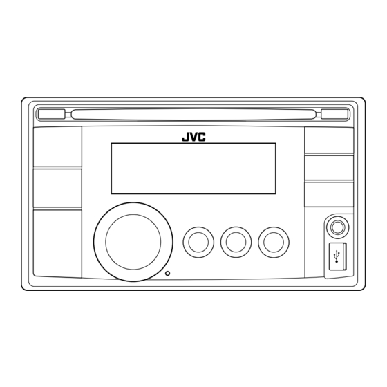
SERVICE MANUAL
2011
7 S ERVICE MANUAL
MA471<Rev.005>
KW-XG56TU, KW-XR411E, KW-XR411EU,
KW-XR411EY, KW-XR414UI, KW-XR416DU,
KW-XR416DUH, KW-XR416DUN,
KW-XR416SUN, KW-XR416U, KW-XR416UH,
KW-XR416UN, KW-XR416UP, KW-XR416UT,
KW-XR417EE, KW-XR418J
only KW-XR418
COPYRIGHT © 2011 Victor Company of Japan, Limited
Lead free solder used in the board (material : Sn-Ag-Cu, melting point : 219 Centigrade)
Lead free solder used in the board (material : Sn-Cu, melting point : 230 Centigrade)
1
PRECAUTION. . . . . . . . . . . . . . . . . . . . . . . . . . . . . . . . . . . . . . . . . . . . . . . . . . . . . . . . . . . . . . . . . . . . . . . . . 1-5
2
Specific Service Instructions . . . . . . . . . . . . . . . . . . . . . . . . . . . . . . . . . . . . . . . . . . . . . . . . . . . . . . 1-8
3
Disassembly . . . . . . . . . . . . . . . . . . . . . . . . . . . . . . . . . . . . . . . . . . . . . . . . . . . . . . . . . . . . . . . . . . . . . . . 1-9
4
Adjustment . . . . . . . . . . . . . . . . . . . . . . . . . . . . . . . . . . . . . . . . . . . . . . . . . . . . . . . . . . . . . . . . . . . . . . . 1-17
5
Troubleshooting . . . . . . . . . . . . . . . . . . . . . . . . . . . . . . . . . . . . . . . . . . . . . . . . . . . . . . . . . . . . . . . . . 1-22
CD RECEIVER
except
KW-XR411/KW-XR417
TABLE OF CONTENTS
COPYRIGHT © 2011 Victor Company of Japan, Limited
for KW-XR411/KW-XR417
No.MA471<Rev.005>
2011/7
Advertisement
Table of Contents

Related Manuals for JVC KW-XG56TU


Summary of Contents for JVC KW-XG56TU
- Page 1 SERVICE MANUAL CD RECEIVER MA471<Rev.005> 2011 7 S ERVICE MANUAL KW-XG56TU, KW-XR411E, KW-XR411EU, KW-XR411EY, KW-XR414UI, KW-XR416DU, KW-XR416DUH, KW-XR416DUN, KW-XR416SUN, KW-XR416U, KW-XR416UH, KW-XR416UN, KW-XR416UP, KW-XR416UT, KW-XR417EE, KW-XR418J only KW-XR418 except KW-XR411/KW-XR417 for KW-XR411/KW-XR417 COPYRIGHT © 2011 Victor Company of Japan, Limited...
- Page 2 SPECIFICATION KW-XR418 AUDIO AMPLIFIER SECTION Power Output 20 W RMS × 4 Channels at 4 Ω and < 1% THD+N 80 dBA (reference: 1 W into 4 Ω) Signal-to-Noise Ratio 4 Ω (4 Ω to 8 Ω allowance) Load Impedance Tone Control Range Bass ±12 dB (60 Hz, 80 Hz, 100 Hz, 200 Hz) Q1.0, Q1.25, Q1.5, Q2.0...
- Page 3 KW-XR411/KW-XR417 AUDIO AMPLIFIER SECTION Maximum Power Output Front/Rear 50 W per channel 20 W per channel into 4 Ω, 40 Hz to 20 000 Hz at no more than 1% total har- Continuous Power Output Front/Rear (RMS) monic distortion. 4 Ω (4 Ω to 8 Ω allowance) Load Impedance Tone Control Range Bass...
- Page 4 KW-XR416/KW-XR414/KW-XG56TU AUDIO AMPLIFIER SECTION Maximum Power Output Front/Rear 50 W per channel 20 W per channel into 4 Ω, 40 Hz to 20 000 Hz at no more than 1% total har- Continuous Power Output Front/Rear (RMS) monic distortion. 4 Ω (4 Ω to 8 Ω allowance)
-
Page 5: Precaution
SECTION 1 PRECAUTION Safety Precautions (1) This design of this product contains special hardware and voltmeter. many circuits and components specially for safety purpos- Move the resistor connection to each exposed metal es. For continued protection, no changes should be made part, particularly any exposed metal part having a return to the original design unless authorized in writing by the path to the chassis, and measure the AC voltage across... - Page 6 Preventing static electricity Electrostatic discharge (ESD), which occurs when static electricity stored in the body, fabric, etc. is discharged, can destroy the laser diode in the traverse unit (optical pickup). Take care to prevent this when performing repairs. 1.5.1 Grounding to prevent damage by static electricity Static electricity in the work area can destroy the optical pickup (laser diode) in devices such as laser products.
- Page 7 Important for laser products 1.CLASS 1 LASER PRODUCT 5.CAUTION : If safety switches malfunction, the laser is able to function. 2.CAUTION : (For U.S.A.) Visible and/or invisible class II laser radiation 6.CAUTION : Use of controls, adjustments or performance of when open.
-
Page 8: Specific Service Instructions
SECTION 2 SPECIFIC SERVICE INSTRUCTIONS This service manual does not describe SPECIFIC SERVICE INSTRUCTIONS. 1-8 (No.MA471<Rev.005>) -
Page 9: Table Of Contents
SECTION 3 DISASSEMBLY Main body (Used model: KW-XR418) 3.1.1 Removing the Front panel (See Fig.1) (2) Remove the three screws C attaching the Bottom chassis. (1) Remove the two screws A attaching the both side of the (See Fig.3) Front panel. (3) Remove the two screws D and two screws E attaching the (2) Disengage four hooks a engaged both side of the Front Heat sink. -
Page 10: See Fig.
3.1.4 Removing the CD mechanism (See Fig.6) 3.1.5 Removing the Switch board (See Fig.7) (1) Remove the three screws L attaching the CD mechanism. (1) Remove the Volume knob. (2) Remove the sixteen screws M attaching the Switch board. Fig.7 Fig.6 CD MECHANISM assembly section •... - Page 11 3.2.2 Removing the top cover (See Fig.3 to 5) (3) Take out the top cover in an upward direction. (See Fig.5.) • Remove the MECHANISM CONTROL BOARD assembly. Top cover (1) From the front side of the CD MECHANISM assembly, change the hook position of the two roller springs.
- Page 12 3.2.4 Removing the PHOTO BOARD assembly (See Fig.7 (3) From the reverse side of the disc plate, remove the screw and 8) D attaching the PHOTO BOARD assembly. (See Fig.8.) • Remove the MECHANISM CONTROL BOARD assembly and top cover. (1) From the bottom side of the top cover, release the projection e from the notch of the disc plate.
- Page 13 3.2.6 Removing the slide cam (L) (See Fig.11 to 13) Reference: • Remove the MECHANISM CONTROL BOARD assembly, top When attaching the slide cam (L), apply grease to the cover and mechanism section. section h. (See Fig.13.) (1) From the top side of the mecha frame, remove the screw F attaching the cam cover.
- Page 14 Reference: 3.2.9 Removing the clamper assembly (See Fig.17) When attaching the slide cam (R) assembly, the f.lock • Remove the MECHANISM CONTROL BOARD assembly, top lever and the link arm apply grease to the section h. cover and mechanism section. (See Fig.14 and 15.) (1) From the top side of the mechanism section, release the clamper spring.
- Page 15 3.2.10 Removing the feed motor (See Fig.18 and 19) 3.2.11 Removing the SWITCH BOARD assembly (See • Remove the MECHANISM CONTROL BOARD assembly, top Fig.18) cover, mechanism section and clamper assembly. • Remove the MECHANISM CONTROL BOARD assembly, top (1) From the bottom side of the T.M chassis assembly, remove cover, mechanism section, clamper assembly and feed motor the two screws G attaching the feed motor assembly.
-
Page 16: No.ma471
3.2.13 Removing the pickup assembly (See Fig.21 to 22) 3.2.14 Removing the spindle motor (See Fig.23 and 24) • Remove the MECHANISM CONTROL BOARD assembly, top • Remove the MECHANISM CONTROL BOARD assembly, cover, mechanism section, clamper assembly and feed motor top cover, mechanism section, clamper assembly, feed motor assembly.)1 -
Page 17: Adjustment
SECTION 4 ADJUSTMENT Test instruments required for adjustment Standard volume position (1) Digital oscilloscope (100MHz) Balance and Bass &Treble volume : lndication"0" (2) Digital tester Loudness : OFF (3) Test Disc Dummy load (4) Extension cable : EXTCD004-28P Exclusive dummy load should be used for AM,and FM. Standard measuring conditions For FM dummy load, there is a loss of 6dB between SSG output Power supply voltage DC14.4V(10.5 to 16V) - Page 18 SERVICE MODE Operating key: [MENU] → [DOWN] (3 sec) Navigation key : Press [SEL] in any main display item to select that option. Volume Knob Turn: forward and backward selection INT ALL Initialize all data to factory shipment state. Note : A disc is inserted, and it is displayed only at the time of CD function. RUNNING MODE 1 CD6 module running mode 1 (Only factory use)
- Page 19 DC OFFSET ERROR INFORMATION 4.7.1 Display indication DC OK DC 1 OK CLR DC1 VOL push to confirm push push DC ERROR DC 1 ERROR BACK BACK knob DC 2 X CLR DC2 VOL push to confirm push BACK 4.7.2 DC offset error distinction. (1) DC ERROR 1 When improper connection or other DC offset errors are detected.
- Page 20 TUNER SERVICE MODE Key operation (FM and AM mode) Enter service mode: [SEL] → [MENU] (3 sec) Exit service mode: press [ENTER] (SEL) key. Go to next item: press [DISP] key Back to previous item: press [BACK] key VER=#*** MICON version display # indicates destination: J=USA, U=OTHERS (eg.
- Page 21 ERROR CODE 4.9.1 Mechanical Error Detail Codes Condition Details Error code Detailed code LOADING Error Error without SW change in LOAD when time-out is done B1 time out When there is no change in the state of the switch from the state 0011 with DISC forward.
-
Page 22: Troubleshooting
SECTION 5 TROUBLESHOOTING 16 PIN CORD DIAGRAM (For KW-XR418) WH/BK GN/BK Black Violet VI/BK GY/BK GN Green Blue Gray WH White Yellow BL/WH GN/BK VI/BK WH/BK GY/BK BL/WH 1-22 (No.MA471<Rev.005>) - Page 23 16 PIN CORD DIAGRAM (For KW-XR411, KW-XR417) Black Green GN/BK WH/BK Gray VI/BK GY/BK Blue Brown White Yellow Violet BL/WH BL/WH BL/WH 13 BR GN/BK VI/BK WH/BK GY/BK VI/BK GY/BK WH/BK GN/BK (No.MA471<Rev.005>)1-23...
- Page 24 16 PIN CORD DIAGRAM (For KW-XR416, KW-XR416D, KW-XR414) WH/BK GN/BK Black Violet VI/BK GY/BK GN Green Blue Gray WH White Yellow BL/WH BL/WH GN/BK VI/BK WH/BK GY/BK 1-24 (No.MA471<Rev.005>)
- Page 25 16 PIN CORD DIAGRAM (For KW-XG56T) Black Green Gray Violet Blue White Yellow WH / BK GN / BK GY / BK VI / BK BL / WH WH / BK GY / BK GY / BK GY / BK WH / BK WH / BK GN / BK...
- Page 26 16 PIN CORD DIAGRAM (For KW-XR416SUN) Black WH/BK GN/BK WH/BK GY/BK Blue VI/BK GY/BK GN/BK Violet VI/BK Green BL/WH White Gray BL/WH Yellow 16 YL BL / WH WH / BK GN / BK VI / BK GY / BK 1-26 (No.MA471<Rev.005>)
- Page 27 (No.MA471<Rev.005>)1-27...
- Page 28 Victor Company of Japan, Limited J&K Car Electronics Corporation 2967-3, Ishikawa-machi, Hachioji-shi, Tokyo, 192-8525, Japan (No.MA471<Rev.005>) Printed in Japan...