Siemens SIMATIC ET 200MP Manual
Interface module im 155-5 pn ba
Hide thumbs
Also See for SIMATIC ET 200MP:
- System manual (126 pages) ,
- Equipment manual (72 pages) ,
- Manual (60 pages)
Table of Contents
Advertisement
Quick Links
Advertisement
Table of Contents

Related Manuals for Siemens SIMATIC ET 200MP


Summary of Contents for Siemens SIMATIC ET 200MP
- Page 2 ___________________ Preface ___________________ Documentation guide ___________________ SIMATIC Product overview ___________________ Wiring ET 200MP Interface module IM 155-5 PN BA ___________________ Interrupts and diagnostic, (6ES7155-5AA00-0AA0) error, and system alarms ___________________ Technical specifications Manual ___________________ Dimension drawing 02/2017 A5E38017683-AA...
- Page 3 Note the following: WARNING Siemens products may only be used for the applications described in the catalog and in the relevant technical documentation. If products and components from other manufacturers are used, these must be recommended or approved by Siemens. Proper transport, storage, installation, assembly, commissioning, operation and maintenance are required to ensure that the products operate safely and without any problems.
-
Page 4: Preface
In order to protect plants, systems, machines and networks against cyber threats, it is necessary to implement – and continuously maintain – a holistic, state-of-the-art industrial security concept. Siemens’ products and solutions only form one element of such a concept. Customer is responsible to prevent unauthorized access to its plants, systems, machines and networks. -
Page 5: Table Of Contents
Table of contents Preface ..............................4 Documentation guide ..........................6 Product overview ..........................10 Properties ..........................10 Functions ..........................12 Wiring ..............................15 Terminal assignment ....................... 15 Block diagram ......................... 16 Interrupts and diagnostic, error, and system alarms ................17 Status and error displays ...................... -
Page 6: Documentation Guide
Documentation guide The documentation for the SIMATIC S7-1500 automation system, the CPU 1516pro-2 PN based on SIMATIC S7-1500 and the SIMATIC ET 200MP distributed I/O system is arranged into three areas. This arrangement enables you to access the specific content you require. - Page 7 You must register once to use the full functionality of "mySupport". You can find "mySupport" on the Internet (https://support.industry.siemens.com/My/ww/en). "mySupport" - Documentation In the Documentation area in "mySupport" you can combine entire manuals or only parts of these to your own manual.
- Page 8 ● Manuals, characteristics, operating manuals, certificates ● Product master data You can find "mySupport" - CAx data on the Internet (http://support.industry.siemens.com/my/ww/en/CAxOnline). Application examples The application examples support you with various tools and examples for solving your automation tasks. Solutions are shown in interplay with multiple components in the system - separated from the focus on individual products.
- Page 9 You can find the SIMATIC Automation Tool on the Internet (https://support.industry.siemens.com/cs/ww/en/view/98161300). PRONETA With SIEMENS PRONETA (PROFINET network analysis), you analyze the PROFINET network during commissioning. PRONETA features two core functions: ● The topology overview independently scans PROFINET and all connected components.
-
Page 10: Product Overview
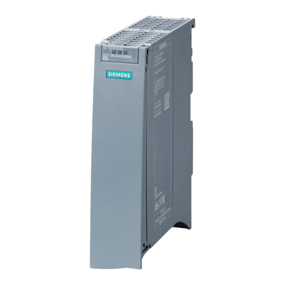
Product overview Properties Article number 6ES7155-5AA00-0AA0 View of the module Figure 2-1 View of the IM 155-5 PN BA interface module Properties ● Technical properties – Connects the ET 200MP distributed I/O system with PROFINET IO – 24V DC power supply (SELV/PELV) –... - Page 11 12 I/O modules can be supplied this way. The exact number of operable modules is determined by the power budget (see relevant section in the S7-1500, ET 200MP automation system (https://support.industry.siemens.com/cs/ww/en/view/59191792) system manual). The interface module IM 155-5 PN BA does not support any additional power supply (PS) modules.
-
Page 12: Functions
● STEP 7 (TIA Portal) as of V14 with HSP 0187 ● With GSD file: The usability of the PROFINET IO functions depends on the configuration software (Siemens and/or third party). Below, the usability of the PROFINET IO functions is described for STEP 7 only. - Page 13 IO devices that have been used in another configuration must be reset to the factory settings before they can be used again (see S7-1500, ET 200MP (https://support.industry.siemens.com/cs/ww/en/view/59191792) system manual). You can find additional information in the STEP 7 online help and ●...
- Page 14 You can find more information on this topic in the STEP 7 online help and ● As of STEP 7 V14, in the PROFINET with STEP 7 V14 (https://support.industry.siemens.com/cs/ww/en/view/49948856) function manual Interface module IM 155-5 PN BA (6ES7155-5AA00-0AA0) Manual, 02/2017, A5E38017683-AA...
-
Page 15: Wiring
If autonegotiation is disabled, the RJ-45 socket (X1 Port 2) has the switch assignment (MDI-X). Reference You can find additional information on connecting the interface module and on the accessories (RJ45 bus connector) in the system manualS7-1500, ET 200MP automation system (https://support.industry.siemens.com/cs/ww/en/view/59191792). Interface module IM 155-5 PN BA (6ES7155-5AA00-0AA0) Manual, 02/2017, A5E38017683-AA... -
Page 16: Block Diagram
Wiring 3.2 Block diagram Block diagram Block diagram The following figure shows the block diagram of the interface module IM 155-5 PN BA. ① Electronics 24 VDC supply voltage ② PROFINET 2-port switch Ground ③ Backplane bus interface LED RUN (green) ④... -
Page 17: Interrupts And Diagnostic, Error, And System Alarms
Interrupts and diagnostic, error, and system alarms Status and error displays Introduction Diagnostics by means of LED display is an initial tool for error localization. To further limit the error, you usually evaluate the display of the CPU, the display of the module status in STEP 7 or the diagnostics buffer of the CPU. - Page 18 Interrupts and diagnostic, error, and system alarms 4.1 Status and error displays Meaning of the LEDs RUN / ERROR / MAINT Table 4- 1 Meaning of the LEDs RUN / ERROR / MAINT LEDs Meaning Remedy ERROR MAINT Supply voltage not present at interface Check the supply voltage or turn it on at the module or too small interface module.
-
Page 19: Interrupts
S7-1500 CPU, to the S7-1500 CPU web server, to the HMI device and in STEP 7. For additional information on the system diagnostics, refer to the System Diagnostics function manual. (https://support.industry.siemens.com/cs/ww/en/view/59192926). Interface module IM 155-5 PN BA (6ES7155-5AA00-0AA0) Manual, 02/2017, A5E38017683-AA... -
Page 20: Triggering Of A Diagnostic Interrupt
Interrupts and diagnostic, error, and system alarms 4.2 Interrupts 4.2.1 Triggering of a diagnostic interrupt Triggering of a diagnostic interrupt For an incoming or outgoing event (e.g., wire break on a channel of an I/O module), the module triggers a diagnostic interrupt if this is configured accordingly in STEP 7 (TIA Portal). The CPU interrupts user program execution and executes the diagnostic interrupt OB. -
Page 21: Alarms
Internet (https://support.industry.siemens.com/cs/ww/en/view/24000238). Causes of error and troubleshooting The error causes and corrective measures of the diagnostic alarms are described in the manuals for the I/O modules (https://support.industry.siemens.com/cs/ww/en/ps/14039/man) in the Interrupts/Diagnostic alarms section. Interface module IM 155-5 PN BA (6ES7155-5AA00-0AA0) -
Page 22: Channel Diagnostics
Error IM power supply: Power supply not active or power sup- ply active Additional information You can find additional information on maximum configuration, power budget and power segments in the S7-1500, ET 200MP automation system (https://support.industry.siemens.com/cs/ww/en/view/59191792) system manual. Interface module IM 155-5 PN BA (6ES7155-5AA00-0AA0) Manual, 02/2017, A5E38017683-AA... -
Page 23: Invalid Configuration States Of The Et 200Mp On Profinet Io
● Faulty backplane bus (e.g., additional IM present). Additional information You can find additional information on maximum configuration and on power budget in the s7-1500, ET 200MP automation system (https://support.industry.siemens.com/cs/ww/en/view/59191792) system manual. See also: Status and error displays (Page 17) 4.3.4... -
Page 24: Technical Specifications
Technical specifications Technical specifications of the IM 155-5 PN BA Order number 6ES7155-5AA00-0AA0 General information Product type designation IM 155-5 PN BA HW functional status FS01 Firmware version V4.0.0 Vendor identification (VendorID) 0x002A Device identifier (DeviceID) 0X0312 Product function Yes; I&M0 to I&M3 I&M data •... - Page 25 Technical specifications Order number 6ES7155-5AA00-0AA0 Power loss Power loss, typ. Address area Address space per module 64 byte; per input / output Address space per module, max. • Address space per station 64 byte; per input / output Address space per station, max. •...
- Page 26 Technical specifications Order number 6ES7155-5AA00-0AA0 PROFINET IO Device Services – Isochronous mode – Open IE communication – – – MRPD – PROFINET system redundancy – PROFIenergy – Prioritized startup – Shared device – Number of IO Controllers with shared device, max. Open IE communication TCP/IP •...
- Page 27 Technical specifications Order number 6ES7155-5AA00-0AA0 Ambient conditions Ambient temperature during operation 0 °C horizontal installation, min. • 60 °C horizontal installation, max. • 0 °C vertical installation, min. • 40 °C vertical installation, max. • Dimensions Width 35 mm Height 147 mm Depth 129 mm...
-
Page 28: Dimension Drawing
Dimension drawing The dimensional drawing of the module on the mounting rail, as well as a dimensional drawing with open front panel, are provided in the appendix. Always observe the specified dimensions for installation in cabinets, control rooms, etc. Dimension drawings of the IM 155-5 PN BA interface module Figure A-1 Dimension drawing of the IM 155-5 PN BA interface module, front and side views Interface module IM 155-5 PN BA (6ES7155-5AA00-0AA0) - Page 29 Dimension drawing Figure A-2 Dimension drawing of theIM 155-5 PN BA interface module, side view with open front cover Interface module IM 155-5 PN BA (6ES7155-5AA00-0AA0) Manual, 02/2017, A5E38017683-AA...