Siemens SIMATIC ET 200MP Manual
Interface module
Hide thumbs
Also See for SIMATIC ET 200MP:
- System manual (126 pages) ,
- Equipment manual (72 pages) ,
- Manual (60 pages)
Table of Contents
Advertisement
Quick Links
IM 155-5 PN ST interface module
(6ES7155-5AA00-0AB0)
SIMATIC
ET 200MP
IM 155-5 PN ST interface module
(6ES7155-5AA00-0AB0)
Manual
08/2013
A5E03612323-02
___________________
Preface
___________________
Documentation guide
___________________
Product overview
___________________
Wiring
___________________
Parameter
Interrupts and diagnostic,
___________________
error, and system alarms
___________________
Technical specifications
___________________
Dimension drawing
___________________
Response times
1
2
3
4
5
6
A
B
Advertisement
Table of Contents

Related Manuals for Siemens SIMATIC ET 200MP


Summary of Contents for Siemens SIMATIC ET 200MP
- Page 1 ___________________ IM 155-5 PN ST interface module Preface (6ES7155-5AA00-0AB0) ___________________ Documentation guide ___________________ Product overview SIMATIC ___________________ Wiring ET 200MP ___________________ IM 155-5 PN ST interface module Parameter (6ES7155-5AA00-0AB0) Interrupts and diagnostic, ___________________ error, and system alarms Manual ___________________ Technical specifications ___________________ Dimension drawing ___________________...
- Page 2 Note the following: WARNING Siemens products may only be used for the applications described in the catalog and in the relevant technical documentation. If products and components from other manufacturers are used, these must be recommended or approved by Siemens. Proper transport, storage, installation, assembly, commissioning, operation and maintenance are required to ensure that the products operate safely and without any problems.
-
Page 3: Preface
Security information Siemens provides automation and drive products with industrial security functions that support the secure operation of plants or machines. They are an important component in a holistic industrial security concept. - Page 4 Preface IM 155-5 PN ST interface module (6ES7155-5AA00-0AB0) Manual, 08/2013, A5E03612323-02...
-
Page 5: Table Of Contents
Table of contents Preface ..............................3 Documentation guide ..........................7 Product overview ............................ 9 Properties ............................9 Functions ............................10 2.2.1 PROFINET IO ..........................10 2.2.2 Configuration control (option handling) ..................14 Wiring ..............................15 Terminal assignment ........................15 Block diagram ..........................16 Parameter ............................. - Page 6 Table of contents IM 155-5 PN ST interface module (6ES7155-5AA00-0AB0) Manual, 08/2013, A5E03612323-02...
-
Page 7: Documentation Guide
From PROFIBUS DP to PROFINET IO • (http://support.automation.siemens.com/W W/view/en/19289930) Programming Manual SIMATIC manuals All current manuals for the SIMATIC products are available for download free of charge from the Internet (http://www.siemens.com/automation/service&support). IM 155-5 PN ST interface module (6ES7155-5AA00-0AB0) Manual, 08/2013, A5E03612323-02... - Page 8 Documentation guide IM 155-5 PN ST interface module (6ES7155-5AA00-0AB0) Manual, 08/2013, A5E03612323-02...
-
Page 9: Product Overview
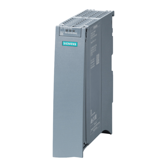
Product overview Properties Order number 6ES7155-5AA00-0AB0 View of the module Figure 2-1 View of the IM 155-5 PN ST interface module Properties ● Technical properties – Connects the ET 200MP distributed I/O system with PROFINET IO – 24V DC power supply (SELV/PELV) –... -
Page 10: Functions
Up to 12 I/O modules can be supplied this way. The exact number of operable modules is determined by the power budget (see relevant section in the ET 200MP distributed I/O system (http://support.automation.siemens.com/WW/view/en/59193214) system manual). ● A maximum of one power supply module (PS) upstream from the interface module and two downstream from the interface module is possible. - Page 11 Media redundancy Shared device Isochronous mode The usability of the PROFINET IOfunctions depends on the configuration software (Siemens and/or third party). Below, the usability of the PROFINET IOfunctions is described for STEP 7only. Isochronous real-time communication Synchronized communication protocol for cyclic exchange of IRT data between PROFINET devices.
- Page 12 You can find additional information in the STEP 7 online help and ● as of STEP 7 V12, in the PROFINET with STEP 7 V12 (http://support.automation.siemens.com/WW/view/en/49948856) function manual. ● as of STEP 7 V5.5 in the PROFINET System Description (http://support.automation.siemens.com/WW/view/en/19292127) manual.
- Page 13 IO devices that have been used in another configuration must be reset to the factory settings before they can be used again (see ET 200MP distributed I/O system (http://support.automation.siemens.com/WW/view/en/59193214) System Manual). You can find additional information in the STEP 7 online help and ●...
-
Page 14: Configuration Control (Option Handling)
Reference You can find more information ● in chapter Configuration control (option handling) (Page 20) ● on the Internet (http://support.automation.siemens.com/WW/view/en/29430270) ● in the STEP 7 online help. IM 155-5 PN ST interface module (6ES7155-5AA00-0AB0) Manual, 08/2013, A5E03612323-02... -
Page 15: Wiring
Ground Ground Additional information You can find additional information on connecting the interface module and on accessories (RJ45 bus connector) in the ET 200MP distributed I/O system (http://support.automation.siemens.com/WW/view/en/59193214) system manual. IM 155-5 PN ST interface module (6ES7155-5AA00-0AB0) Manual, 08/2013, A5E03612323-02... -
Page 16: Block Diagram
Wiring 3.2 Block diagram Block diagram Block diagram Figure 3-1 Block diagram of the IM 155-5 PN ST interface module IM 155-5 PN ST interface module (6ES7155-5AA00-0AB0) Manual, 08/2013, A5E03612323-02... -
Page 17: Parameter
Parameter Parameters Table 4- 1 Parameters for IM 155-5 PN ST interface module Parameters Value range Default setting Efficiency range Connection to supply voltage Connection/No Connection ET 200MP connection Configuration control Disable/enable Disable ET 200MP IM 155-5 PN ST interface module (6ES7155-5AA00-0AB0) Manual, 08/2013, A5E03612323-02... -
Page 18: Description Of Parameters
Reference See the section on the power budget and the forming of power segments in the ET 200MP distributed I/O system (http://support.automation.siemens.com/WW/view/en/59193214) System Manual. IM 155-5 PN ST interface module (6ES7155-5AA00-0AB0) Manual, 08/2013, A5E03612323-02... -
Page 19: Configuration Control
Parameter 4.2 Description of parameters Requirement In order to generate a diagnostics, the IM 155-5 PN ST interface module must have been configured once. See also Diagnostic alarms (Page 35) 4.2.2 Configuration control "Configuration control" parameter You can use this parameter to enable the configuration control function in the ET 200MP distributed I/O system. -
Page 20: Configuration Control (Option Handling)
Parameter 4.3 Configuration control (option handling) Configuration control (option handling) 4.3.1 Configuration control and control data record Operating principle Configuration control allows you to operate various real configurations (options) with a single configuration of the ET 200MP distributed I/O system. We distinguish between the following procedures: ●... - Page 21 Parameter 4.3 Configuration control (option handling) Control data record A control data record 196 is defined for the configuration control that receives a slot assignment. Table 4- 3 Control data record Byte Element Code Explanation Block length 4 + number of slots Header Block ID Version...
- Page 22 (Page 9) and the "Power budget calculation" chapter in the system manual ET 200MP Distributed I/O System (http://support.automation.siemens.com/WW/view/en/59193214). Particularly for a power supply (PS) module on slot 0, we recommend that you avoid reconfiguration.
- Page 23 Parameter 4.3 Configuration control (option handling) Error messages The following error messages are returned if an error occurs during writing of the control data record: Table 4- 5 Error messages Error code Meaning 80B1 Invalid length 80B5 Configuration control not configured 80B6 Data record does not originate from the IO controller which subscribed to the interface module...
-
Page 24: Feedback Data Record
Parameter 4.3 Configuration control (option handling) 4.3.2 Feedback data record Feedback data record The feedback data record is mapped by a separate data record 197. The feedback data record exists only when configuration control is configured and always refers to the maximum quantity framework without interface module, i.e., 31 slots. The following applies here: ●... -
Page 25: Configure Configuration Control Without Empty Slots
Parameter 4.3 Configuration control (option handling) Error messages The following error messages are returned if an error occurs during reading of the feedback data record: Table 4- 7 Error messages Error code Meaning 80B1 Invalid length 80B5 Configuration control not configured 80B8 Parameter error 4.3.3... - Page 26 Parameter 4.3 Configuration control (option handling) Data record of the example The following table shows the structure of the control data record for the above example. Table 4- 8 Data record for example "Configure configuration control without empty slots" Byte Element Code Explanation...
-
Page 27: Extending The Configuration
Parameter 4.3 Configuration control (option handling) 4.3.4 Extending the configuration Principle of operation You can add modules at the end of the configuration with this procedure. The configured configuration can also be extended from the center based on freely selectable slot assignment. - Page 28 Parameter 4.3 Configuration control (option handling) Data record of the example The following table shows the structure of the control data record for the above example. Table 4- 9 Data record for example "Extending the configuration" Byte Element Code Explanation Block length Header Block ID...
-
Page 29: Combining Configurations
Parameter 4.3 Configuration control (option handling) 4.3.5 Combining configurations Principle of operation You can combine the different procedures with configuration control. Figure 4-3 Combining configurations IM 155-5 PN ST interface module (6ES7155-5AA00-0AB0) Manual, 08/2013, A5E03612323-02... - Page 30 Parameter 4.3 Configuration control (option handling) Data record of the example The following table shows the structure of the control data record for the above example. Table 4- 10 Data record for example "Combining configurations" Byte Element Code Code Explanation configuration 1 configuration 2 Block length...
-
Page 31: Interrupts And Diagnostic, Error, And System Alarms
Interrupts and diagnostic, error, and system alarms Status and error displays Introduction Diagnostics by means of LED display is an initial tool for error localization. To further limit the error, you usually evaluate the display of the CPU, the display of the module status in STEP 7 or the diagnostics buffer of the CPU. - Page 32 Interrupts and diagnostic, error, and system alarms 5.1 Status and error displays Meaning of the LEDs RUN/ ERROR/ MAINT Table 5- 1 Meaning of the LEDs RUN/ ERROR/ MAINT LEDs Meaning Remedy ERROR MAINT Supply voltage not present at interface Check the supply voltage or turn it on at the module or too small interface module.
-
Page 33: Interrupts
S7-1500 CPU, to the S7-1500 CPU web server, to the HMI device and in STEP 7. For additional information on the system diagnostics, refer to the System Diagnostics function manual. (http://support.automation.siemens.com/WW/view/en/59192926). IM 155-5 PN ST interface module (6ES7155-5AA00-0AB0) Manual, 08/2013, A5E03612323-02... -
Page 34: Triggering Of A Diagnostic Interrupt
Interrupts and diagnostic, error, and system alarms 5.2 Interrupts 5.2.1 Triggering of a diagnostic interrupt Triggering of a diagnostic interrupt For an incoming or outgoing event (e.g., wire break on a channel of an I/O module), the module triggers a diagnostic interrupt if this is configured accordingly in STEP 7 (TIA Portal). The CPU interrupts user program execution and executes the diagnostic interrupt OB. -
Page 35: Alarms
You can find the structure of the diagnostic data records and programming examples in the programming manual From PROFIBUS DP to PROFINET IO (http://support.automation.siemens.com/WW/view/en/19289930) and in the application example on the Internet (http://support.automation.siemens.com/WW/view/en/24000238). IM 155-5 PN ST interface module (6ES7155-5AA00-0AB0) -
Page 36: Maintenance Events
Interrupts and diagnostic, error, and system alarms 5.3 Alarms Causes of error and troubleshooting The causes of error and troubleshooting of the diagnostic alarms are described in the device manuals of the I/O modules in the section Interrupts/Diagnostic alarms. See also Channel diagnostics (Page 37) 5.3.2 Maintenance events... -
Page 37: Channel Diagnostics
Interrupts and diagnostic, error, and system alarms 5.3 Alarms 5.3.3 Channel diagnostics Function Channel diagnostics provides information about channel faults in modules. Channel faults are mapped as channel diagnostic data in IO diagnostic data records. The "RDREC" instruction is used to read the data record. Structure of the diagnostic data records The data records supported by the ET 200MP are based on the PROFINET IO standard - Application Layer Service Definition V2.2. - Page 38 5.3 Alarms Additional information You can find additional information on maximum configuration, power budget and power segments in the ET 200MP distributed I/O system (http://support.automation.siemens.com/WW/view/en/59193214) System Manual. Structure USI = W#16#0001 Table 5- 7 Structure of USI = W#16#0001 Data block name...
- Page 39 Interrupts and diagnostic, error, and system alarms 5.3 Alarms USI structure = W#16#0003 Table 5- 9 USI structure = W#16#0003 Data block name Contents Note Bytes W#16#0003 Manufacturer-specific diagnostic data if the permitted number of I/O modules is exceeded The first surplus module is located in slot: <No.> Slot B#16#20 to B#16#FF Followed by 3 reserved bytes...
- Page 40 Interrupts and diagnostic, error, and system alarms 5.3 Alarms USI structure = W#16#0006 Table 5- 12 USI structure = W#16#0006 Data block name Contents Note Bytes W#16#0006 Manufacturer-specific diagnostic data if the communication with a slot has failed Communication has failed with slot: <No.> Slot B#16#00 to B#16#1F Followed by 3 reserved bytes...
-
Page 41: Invalid Configuration States Of The Et 200Mp On Profinet Io
Additional information You can find additional information on maximum configuration, power budget and power segments in the ET 200MP distributed I/O system (http://support.automation.siemens.com/WW/view/en/59193214) System Manual. See also: Status and error displays (Page 31) 5.3.5 STOP of the IO controller and recovery of the IO device... - Page 42 Interrupts and diagnostic, error, and system alarms 5.3 Alarms IM 155-5 PN ST interface module (6ES7155-5AA00-0AB0) Manual, 08/2013, A5E03612323-02...
-
Page 43: Technical Specifications
Technical specifications Technical specifications of the IM 155-5 PN ST 6ES7155-5AA00-0AB0 Product type designation IM 155-5 PN ST General information Hardware version Firmware version V2.0.0 Vendor identifier (VendorID) 0x002A Device identifier (DeviceID) 0x0312 Product function I&M data Yes; IM0 to IM3 Engineering with STEP 7 TIA Portal can be configured/integrated V12.0 / V12.0... - Page 44 Technical specifications 6ES7155-5AA00-0AB0 Address area Address space per module Address space per module, max. 256 byte; per input/output Address space per station Address space per station, max. 512 byte; per input/output Hardware configuration System power supply can be plugged in to left of Number of permissible power segments Modules per rack, max.
- Page 45 Technical specifications 6ES7155-5AA00-0AB0 Open IE communication TCP/IP SNMP LLDP Isochronous mode Isochronous mode (application synchronized up to terminal) Constant bus cycle time shortest clock pulse 250 µs maximum clock pulse 4 ms Interrupts/diagnostics/status information Status display Interrupts Interrupts Diagnostic alarms Diagnostic functions Diagnostic indicator LED RUN LED...
- Page 46 Technical specifications IM 155-5 PN ST interface module (6ES7155-5AA00-0AB0) Manual, 08/2013, A5E03612323-02...
-
Page 47: Dimension Drawing
Dimension drawing The dimensional drawing of the module on the mounting rail, as well as a dimensional drawing with open front panel, are provided in the appendix. Always observe the specified dimensions for installation in cabinets, control rooms, etc. Dimensional drawings of the IM 155-5 PN ST interface module Figure A-1 Dimensional drawing of the IM 155-5 PN ST interface module, front and side views IM 155-5 PN ST interface module (6ES7155-5AA00-0AB0) - Page 48 Dimension drawing Dimensional drawing of the IM 155-5 PN ST interface module, side view with open front cover Figure A-2 Dimensional drawing of the IM 155-5 PN ST interface module, side view with open front cover IM 155-5 PN ST interface module (6ES7155-5AA00-0AB0) Manual, 08/2013, A5E03612323-02...
-
Page 49: Response Times
Response times Response times of the ET 200MP Introduction The response time of the IM 155-5 PN ST is made up of: ● the update time configured for the IM as IO device. plus ● the backplane bus cycle time. Note Validity of the formula The following formula does not apply to shared device mode. - Page 50 Response times B.1 Response times of the ET 200MP Example configuration for the calculation of the backplane bus cycle time The following are used in the example: Table B- 1 Example configuration for the calculation of the backplane bus cycle time I/O module Output data Input data...
- Page 51 Response times B.1 Response times of the ET 200MP Calculating the response time It is necessary to differentiate between two cases when calculating the response time of the IM 155-5 PN ST: ● Case 1: The configured update time is greater than/equal to the backplane bus cycle time.
- Page 52 Response times B.1 Response times of the ET 200MP IM 155-5 PN ST interface module (6ES7155-5AA00-0AB0) Manual, 08/2013, A5E03612323-02...