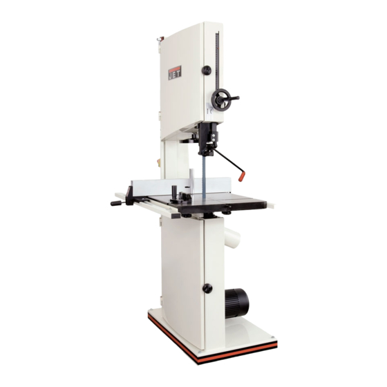
Jet JWBS-20 Owner's Manual
Woodworking bandsaw
Hide thumbs
Also See for JWBS-20:
- Operating instructions manual (56 pages) ,
- Operating instructions and parts manual (32 pages) ,
- Operating instructions and parts manual (68 pages)

Related Manuals for Jet JWBS-20


Summary of Contents for Jet JWBS-20
- Page 1 OWNER'S MANUAL JWBS-20 Woodworking Bandsaw JET EQUIPMENT & TOOLS, INC. A WMH Company www.jettools.com P.O. BOX 1349 Auburn, WA 98071-1349 e-mail jet@jettools.com Phone: 253-351-6000 Fax: 1-800-274-6840 M-708752 11/01...
-
Page 2: Warranty
This manual has been prepared for the owner and operators of a JET JWBS-20 Woodworking Bandsaw. Its purpose, aside from machine operation, is to promote safety through the use of accepted correct operating and maintenance procedures. Completely read the safety and maintenance instructions before operating or servicing the machine. -
Page 3: Warnings
1. Read and understand the entire instruction manual before attempting assembly or operation. 2. This band saw is designed and intended for use by properly trained and experienced personnel only. If you are not familiar with the proper and safe operation of a bandsaw, do not use until proper training and knowledge have been obtained. -
Page 4: Table Of Contents
The specifications in this manual are given as general information and are not binding. JET Equipment and Tools reserves the right to effect, at any time and without prior notice, changes or alterations to parts, fittings, and accessory equipment deemed necessary for any reason whatsoever. JWBS-20... -
Page 5: Contents Of Shipping Container
9. Lock Washers Unpacking and Setup 1. Remove the crate and packing material from the saw except for the transport skid on the bottom. 2. Move the saw to its permanent working location. The site should be dry, well lit, and... -
Page 6: Upper Bearing Guide Adjustment
Tighten wing nut. 6. Adjust the opposite side bearing. 7. Check to make sure the adjustments have not changed and the bearing guides do not pinch the blade. The JWBS-20... -
Page 7: Lower Bearing Guide Adjustment
Remove the table insert (F, Fig. 5) and table pin (G, Fig. 5). 2. Slide saw blade through slot in table where the table pin was located. Rotate the table 90 degrees so that the miter slot is parallel to the blade, and to the right of the blade when facing the bandsaw. -
Page 8: Adjusting 90 Degree Table Stop
Adjusting 90 Degree Table Stop 1. Blade tension must be properly adjusted prior to adjusting 90 degree stop, see “Adjusting Blade Tension” page 13. 2. Loosen lock knobs (A, Fig. 7) and tilt table until it rests against table stop bolt (B, Fig. 7). -
Page 9: Fence Assembly And Adjustment
Fence Assembly and Adjustment 1. Attach the fence (A, Fig. 10) to the fence body (B, Fig. 10) with four 5/16” x 3/4” hex cap bolts, four 5/16” lock washers, and four 5/16” flat washers. 2. Thread a hex nut (D, Fig. 11) onto the pad’s threaded stud (E, Fig. -
Page 10: Resaw Guide
Resaw Guide For resawing attach the post (A, Fig. 13) to fence with the lock knob (B, Fig. 13). There is a slotted hole in the fence that will accommodate the resaw kit. Position the post so that it is centered with the front edge of the blade. -
Page 11: Changing Blades
WARNING Disconnect machine from the power source, unplug! Blade teeth are sharp! Use care when handling the saw blade. Failure to comply may cause serious injury! 1. Disconnect the machine from the power source. 2. Remove the table insert (A, Fig. 16), and table pin (B, Fig. -
Page 12: Adjusting Blade Tension
4. If adjustment is necessary, loosen the wing nut (E, Fig. 19) at the top rear of the saw. 5. Adjust tracking by turning the knob (C, Fig. 19) in 1/4 turn increments. Rotate the wheel forward, and observe the position of the blade on the wheel. -
Page 13: Brake Pedal
Brake Pedal Depress the brake pedal (A, Fig. 20) while the saw is running to stop the saw. Re-start the saw by pressing the on switch. Replacing Belt 1. Disconnect the machine from the power source. 2. Release blade tension by turning blade tension hand wheel clockwise. -
Page 14: Electrical Connections
Failure to comply may result in loss of property and/or serious injury! JWBS-20 is rated at 2 HP, 1Ph, 230V only. A plug needs to be purchased for the bandsaw that matches the outlet you intend to use (A, Fig. -
Page 15: Troubleshooting
Trouble Saw stops or will not start Does not make accurate 45 or 90 cuts Blade wanders during cut Saw makes unsatisfactory cuts Blade does not come up to speed Saw vibrates excessively Troubleshooting Possible Cause 1. Overload tripped 2. Saw unplugged 3. -
Page 16: Part's Breakdowns And Part's List
Upper Wheel Assembly... - Page 17 Index Part 1...JWBS20-501... Saw Body ..1 2...JWBS20-49... Key... 7 x 7 x 25 ... 1 3...BB-6205LLU ... Ball Bearing... 6205 ... 2 4...TS-0720091 ... Lock Washer ... 3/8 ... 1 5...JWBS20-44... Upper Wheel Bearing Bracket ..1 6...JWBS20-506...
- Page 18 Lower Wheel and Motor Assembly...
- Page 19 Index Part 1...JWBS20-201... Bearing Base..1 2...JWBS20-62... Adjusting Bolt ..4 3...TS-0720091 ... Lock Washer ...3/8 ... 6 4...TS-0060081 ... Hex Cap Bolt ...3/8 x 1-3/4... 4 5...BB-6205ZZ ... Ball Bearing...6205... 2 6...JWBS20-206... Spindle ..1 7...JWBS20-49... Key...7 x 7 x 25 ... 1 8...TS-0680021 ...
- Page 20 Index Part Description Size Qty. 51 ...JWBS20-84... Spring..1 52 ...JWBS24-81A ... Plate..2 53 ...JWBS20-82... Brake Locking Bracket..2 54 ...JWBS20-254... Brake Pedal..1 55 ...TS-0207061 ... Socket Head Cap Screw...1/4-20 x 1... 1 56 ...TS-0561031 ... Hex Nut ...3/8-16 ... 1 57 ...JWBS20-257...
- Page 21 Blade Guides Assembly...
- Page 22 Blade Guides Assembly Index Part Description Size Qty. 1...TS-0051051 ... Hex Cap Bolt ...5/16-18 x 1... 4 2...TS-0720081 ... Lock Washer ...5/16... 4 3...TS-0680031 ... Flat Washer...5/16... 8 4...JWBS20-304... Guide Bar Bracket ..1 5...JWBS18-305 ... Worm ..1 6...JWBS18-306...
- Page 23 Index Part Description Size Qty. 56 ...TS-0720071 ... Lock Washer ...1/4 ... 1 57 ...JWBS20-357... Hex Socket Cap Screw...3/16 x 3/8... 2 58 ...JWBS20-358... Bearing Bracket..1 59 ...TS-0207031 ... Socket Head Cap Screw...1/4-20 x 5/8... 2 60 ...JWBS20-360... Bracket..1...
- Page 24 Table Assembly...
- Page 25 Index Part 1...JWBS18-401... Locking Handle..1 2...TS-0680021 ... Flat Washer...1/4 ... 11 3...JWBS18-403... Miter Gauge Body ..1 4...JWBS20-156... Guide Disc..1 5...JWBS18-405... Pan Head Screw...M6 x 8... 1 6...JWBS18-406... Pointer..1 7...JWBS18-407... Guide Bar..1 8...JWBS18-408N ...
-
Page 26: Electrical Schematics
Electrical Schematic - 230V, 1 Ph...