Endress+Hauser NRF590 Operating Instruction
Tank side monitor
Hide thumbs
Also See for NRF590:
- Operating instructions manual (96 pages) ,
- Technical information (36 pages)
Table of Contents
Advertisement
Quick Links
Download this manual
See also:
Technical Information
KA01070F/00/EN/15.15
71307019
Valid as of software version:
V02.04.zz
Products
Brief Operating Instructions
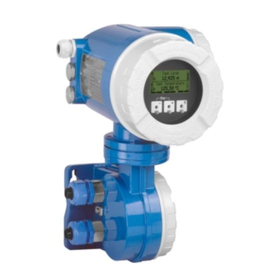
Tank Side Monitor NRF590
Inventory Control
These Instructions are Brief Operating Instructions; they do not
replace the Operating Instructions included in the scope of
supply.
For detailed information, refer to the Operating Instructions and
other documentation on the CD-ROM provided or visit
"www.endress.com/deviceviewer".
Solutions
Services
Advertisement
Table of Contents

Related Manuals for Endress+Hauser NRF590


Summary of Contents for Endress+Hauser NRF590
- Page 1 KA01070F/00/EN/15.15 71307019 Valid as of software version: V02.04.zz Brief Operating Instructions Tank Side Monitor NRF590 Inventory Control These Instructions are Brief Operating Instructions; they do not replace the Operating Instructions included in the scope of supply. For detailed information, refer to the Operating Instructions and other documentation on the CD-ROM provided or visit "www.endress.com/deviceviewer".
-
Page 2: Table Of Contents
Table of contents Tank Side Monitor NRF590 Table of contents 1 Safety instructions ............. 3 1.1 Designated use . -
Page 3: Safety Instructions
Safety instructions Designated use The Tank Side Monitor NRF590 is a monitoring unit for use with the Endress+Hauser Micropilot M and Micropilot S-series radars and other HART compatible instruments. Mounted at the tank side, the NRF590 provides indication of measured data, allows configuration and supplies intrinsically safe (i.s.) power to the connected sensors on the tank. -
Page 4: Operational Safety And Process Safety
Safety instructions Tank Side Monitor NRF590 Operational safety and process safety • Alternative monitoring measures must be taken to ensure operational safety and process safety during confiugration, testing and maintenance work on the instrument. • The instrument is safely built and tested according to state-of-the-art technology and has left the factory in perfect condition as regards technical safety. -
Page 5: Safety Icons
Tank Side Monitor NRF590 Safety instructions Safety icons Safety conventions Warning! A warning highlights actions or procedures which, if not performed correctly, will lead to personal injury, a safety hazard or destruction of the instrument. Caution! " Caution highlights actions or procedures which, if not performed correctly, may lead to personal injury or incorrect functioning of the instrument. -
Page 6: Mounting
Mounting Tank Side Monitor NRF590 Mounting Design, dimensions 242 (9.53) 150 (6.0) 114 (4.5) EEx d Electronic compartment with LCD Non-i.s. terminal compartment (EEx d) Terminal compartment for all i.s. wiring (3.94) mm (inch) L00-NRF590-06-00-06-en-001 Endress+Hauser... -
Page 7: Installation Variants
Tank Side Monitor NRF590 Mounting Installation variants 2.2.1 Mounting kit You need the following tools: • 3 mm (7/64") Allen wrench for loosening and tightening the locking screw. • 4 mm (0.16 in) Allen wrench for turning the housing. 2.2.2 Wall mounting 100 (3.94) - Page 8 Mounting Tank Side Monitor NRF590 2.2.3 Mounting on vertical rail ø90 (ø3.5) maximum Rail mounting kit (Order No.: 52013134) Grounding connections mm (inch) L00-NRF590-17-00-06-en-002 2.2.4 Mounting on horizontal rail Rail mounting kit (Oder No.: 52013134) ø90 (ø3.5) maximum mm (inch)
-
Page 9: Turn Housing
Tank Side Monitor NRF590 Mounting Turn housing For easy access to the display or the terminal compartment, the upper part of the housing can be rotated into an arbitrary position. In order to do this, perform the following steps: Loosen the alignment pin using a 4 mm (0.16 in) Allen key (approx. -
Page 10: Rotating The Display Module
Mounting Tank Side Monitor NRF590 Rotating the display module In order to facilitate operation and reading of the measuring value, the display module can be rotated in the following way: Warning! Danger from elctrical schock! Switch off power supply before opening the housing. -
Page 11: Grounding
Tank Side Monitor NRF590 Mounting Grounding The NRF590 must be grounded to the tank potential before communication and power connections are made. The connections (A 4mm ) from each outer ground plug of the NRF590 to the tank ground must be made before any other wiring connections are made. All grounding must be compliant with local and company regulations and checked before the equipment is commissioned. -
Page 12: Post-Installation Check
Mounting Tank Side Monitor NRF590 Post-installation check After the Tank Side Monitor has been installed, perform the following checks: • Is the measuring instrument damaged (visual check)? • Have the mounting bolts been tightend securely? • Are both grounding terminals connected to tank ground? -
Page 13: Wiring
Tank Side Monitor NRF590 Wiring Wiring Wiring the Non-IS (Ex d) connections 3.1.1 The procedure " Caution! Before starting the wiring procedure, make sure that the supply voltage is switched off. Using a 3mm (7/64") Allen wrench, ➁ losen the safety pin for the lid. - Page 14 Wiring Tank Side Monitor NRF590 3.1.2 Terminal assignment of the field protocol/host side For the certificate versions - Standard (not certified) - ATEX 01 L/+ - FM Power - CSA 02 N/- 04 A1/+ Digital I/O A 05 A2/- 06 B1/+...
- Page 15 Tank Side Monitor NRF590 Wiring Terminal A1/+ A2/- B1/+ B2/- Discrete I/O A Discrete I/O B Discrete I/O B Cable Power supply Discrete I/O A - screen 4 to 20 mA 4 to 20 mA output #1 discrete discrete output...
- Page 16 ) wire, connect the EIA-485 at terminal 9 and 10. • Termination of the EIA-485 bus at the NRF590 can be set in the operating menu (only enable on end instrument in a loop). • Connect the 3rd wire from the control system signal common (0V) to terminal 11 or 12.
- Page 17 "00 S" at the NRF590 and to ground at the other end. The "00S" terminal provides a 500V capacitor between the cable screen and tank ground potential.
- Page 18 Note! 250VAC is the maximum load that can be connected. 3.1.10 Connection of a Proservo NMS5 to the non-i.s. HART input It is possible to connect Proservo NMS5 to the Tank Side Monitor NRF590 using the non-i.s. HART input available in the Exd terminal compartment.
- Page 19 Tank Side Monitor NRF590 Wiring NRF590 01 L/+ 02 N/- 04 A1/+ 05 A2/- 06 B1/+ 07 B2/- 00 S 08 C1 09 C2 10 C3 11 C4 12 C5 13 C6 14 C7 15 C8 NMS5 CTR2 OT1+ OT2+...
- Page 20 BottomLevel Bottom Level 8n25 Tank Side Monitor NRF590 settings NRF590 settings to start communication with NMS5. Go to the "Analog I/O" (7xxx) menu. Go to "Analog Out" (73xx). Go to the "HART Master" (735x) submenu. Go to "Fixed current" (7351).
-
Page 21: Wiring The Is (Ex Ia) Connection
Tank Side Monitor NRF590 Wiring Wiring the IS (Ex ia) connection 3.2.1 The procedure " Caution! The diameter of the signal cable should allow tight closing of the cable glands. Example: • Tank Side Monitor: M25x1.5 • Micropilot S: M20x1.5 ... -
Page 22: Terminal Assignment
Wiring Tank Side Monitor NRF590 3.2.2 Terminal assignment NRF590 - i.s. terminal board Internally HART interconnected sensor as one HART fieldbus loop For Micropilot S-series only! L00-NRF590-04-00-08-en-018 Terminal Designation Meaning Terminal Designation Meaning + RTD drive +HART Komm. ) ) + RTD sense -HART Komm. - Page 23 P+ and P-. Although it is possible to use only 3 wires between the S-series radar and the NRF590, by combining the P- and H- wires, it is recommended to use a double pair of screened and twisted cable.
- Page 24 Tank Side Monitor, not at the Micropilot S. 2 3 4 A0020823 Tank Side Monitor NRF590 Micropilot S Only for Micropilot S Intrinsically safe terminal board Grounding single sided on Tank Side Monitor NRF590 HART Sensor PML (potential equalization line) Endress+Hauser...
- Page 25 Tank Side Monitor NRF590 Wiring If there is no way to set a ground cable between NRF590 and Micropilot S it is possible to ground single side (grounding on side NRF590). In this case it’s imperative to ground the shield (on Micropilot S side) via a ceramic capacitor with a maximum capacitance of 10 nF and a minimum insulating voltage of 1500 V.
-
Page 26: Operation
Operation Tank Side Monitor NRF590 Operation Entering the menu The navigation in the operating menu always starts from the main screen (measured value display). From there, the following three menus can be entered by the keys: Shortcut Menu Main Menu... -
Page 27: Key Assignment
Tank Side Monitor NRF590 Operation Key assignment 4.2.1 Function of the key Key(s) Meaning Escape Escape from the current editing opration. If the currently edited value has not been stored , then the parameter will retain its original value. Display contrast Opens the menu for the setting of the display contrast. - Page 28 Operation Tank Side Monitor NRF590 Example Softkey symbols to next edit current move move mark current to previous Meaning parameter parameter downwards upwards selection parameter L00-NRF590-07-00-00-en-003 List of the softkey symbols Softkey symbol Meaning Move to the previous parameter in the list.
-
Page 29: Display Symbols
Tank Side Monitor NRF590 Operation 4.2.2 Display symbols The following table describes the symbols that appear on the liquid crystal display: Symbol Meaning Status of the Tank Side Monitor W&M locking is displayed, if the W&M parameters of the Tank Side Monitor have been locked by the hardware locking switch. - Page 30 Operation Tank Side Monitor NRF590 Symbol Meaning Parameter type Read only indicates a measured or calculated value. Editable indicates a configuration parameter. W&M locked indicates the current parameter is locked by the W&M switch. Cyclic update (flashing left of the parameter name) indicates that the parameter is cyclically updated These parameters are linked to an external HART instrument.
-
Page 31: Commissioning
– the analog or digital outputs via the Analog (AO) and Digital (DO) output blocks. 5.1.2 Linking sensors to function blocks To commission the NRF590, it is necessary to connect all Tank HART sensor blocks to one of the internal function blocks, either the "tank functions" block or the "alarm function" block. The outputs of these function blocks can then be mapped to the display, the fieldbus function block and the AO or DO blocks.By default, these mappings are set to the most common default values. - Page 32 Commissioning Tank Side Monitor NRF590 5.1.4 Example of block linking DISPLAY Primary Value Sec. Value 1 Sec. Value 2 Sec. Value 3 Sec. Value 4 FMR23x HART FMR53x FMR54x TANK MODBUS PV Value Level Ref Level Level Meas. Level Level % Level % Meas.
- Page 33 Tank Side Monitor NRF590 Commissioning Additionally, a digital input value is directly transferred from the Digital Input block (IS DI#1) to a Digital Output block (DO#B) as well as an analog value from the Analog Input Block (IS AI) to the MODBUS Block.
-
Page 34: Configuration Of The Hart Interface
In this mode the Tank Side Monitor can poll HART instruments which are connected to the Ex d HART bus. For a specification of the modes see BA00256F/00/EN. The Ex d HART bus is not available on a Modbus NRF590 with order code *4********* (without 4 to 20mA Input or Output). Endress+Hauser... -
Page 35: Addressing Of The Hart Instruments
Tank Side Monitor NRF590 Commissioning Addressing of the HART instruments If possible, the addresses of the HART instruments should be set before connection to the Tank Side Monitor. The default block configurations require usage of the following addresses: Addresses of the individual HART instruments... -
Page 36: Steps Of The Commissioning Procedure
Note! Only Tank values will be diesplayed in NRF590 units, values directly form HART instruments will be displayed in the HART instruments units. In the Software Version SW 02.01, the HART buses on the IS and on the non-IS side are continuously monitored by the Tank Side Monitor. - Page 37 Commissioning Configure the connected HART instruments After connecting all HART instruments to the HART multidrop line of the NRF590, these gauges can be configured via the NRF590 Tank Side Monitor display. In the "HART instruments"(8---) function group, all connected instruments are displayed with their respective HART address in brackets (e.g.
- Page 38 Commissioning Tank Side Monitor NRF590 Define Alarm Functions a. Alarm type and limits For all input variables, alarm limits can be defined. In the "Alarm"(5---) function group, the alarm type (level, temperature, various) and the alarm behaviour can be selected.
- Page 39 Tank Side Monitor NRF590 Commissioning (9223) –"V01 Map. Mode" must be set to "Integer Vals." if access to software V01 compatible register map is required. – "0% value" and "100% value" must be configured to obtain correct integer values (see BA00256F/00/EN, Chapter "Configuring the Modbus Integer Scaling")
- Page 40 71307019 www.addresses.endress.com...