
Related Manuals for Siemens RUGGEDCOM RS900W


Summary of Contents for Siemens RUGGEDCOM RS900W
- Page 1 Preface Introduction Installing the Device RUGGEDCOM RS900W Communication Ports Technical Specifications Dimension Drawings Installation Guide Certification 08/2017 RC1028-EN-06...
-
Page 2: Security Information
Warranty Siemens warrants this product for a period of five (5) years from the date of purchase, conditional upon the return to factory for maintenance during the warranty term. This product contains no user-serviceable parts. Attempted service by unauthorized personnel shall render all warranties null and void. - Page 3 RUGGEDCOM RS900W Installation Guide Contacting Siemens Address Telephone E-mail Siemens Canada Ltd Toll-free: 1 888 264 0006 ruggedcom.info.i-ia@siemens.com Industry Sector Tel: +1 905 856 5288 300 Applewood Crescent Fax: +1 905 856 1995 Concord, Ontario www.siemens.com/ruggedcom Canada, L4K 5C7...
- Page 4 RUGGEDCOM RS900W Installation Guide...
-
Page 5: Table Of Contents
RUGGEDCOM RS900W Installation Guide Table of Contents Table of Contents Preface ......................Alerts ..............................vii Related Documents ..........................viii Accessing Documentation ........................viii Training ............................viii Customer Support ..........................viii Chapter 1 Introduction ..................... 1.1 Feature Highlights ........................1 1.2 Description ........................... 2 Chapter 2 Installing the Device .................. - Page 6 RUGGEDCOM RS900W Table of Contents Installation Guide 3.3.1 Supported Wireless Standards ................... 20 3.3.2 Radio Characteristics ......................20 3.3.3 Channel Allocations for IEEE 802.11b/g ................21 Chapter 4 Technical Specifications .................. 4.1 Power Supply Specifications ......................23 4.2 Failsafe Relay Specifications ......................24 4.3 Copper Ethernet Port Specifications ....................24 4.4 Fiber Optic Ethernet Port Specifications ..................
-
Page 7: Preface
Installation Guide Preface Preface This guide describes the RUGGEDCOM RS900W. It describes the major features of the device, installation, commissioning and important technical specifications. It is intended for use by network technical support personnel who are responsible for the installation, commissioning and maintenance of the device. -
Page 8: Related Documents
Siemens Sales representative. Customer Support Customer support is available 24 hours, 7 days a week for all Siemens customers. For technical support or general information, contact Siemens Customer Support through any of the following methods: Online Visit http://www.siemens.com/automation/support-request... - Page 9 RUGGEDCOM RS900W Installation Guide Preface • Ask questions or share knowledge with fellow Siemens customers and the support community Customer Support...
- Page 10 RUGGEDCOM RS900W Preface Installation Guide Customer Support...
-
Page 11: Introduction
2), optional conformal coating and a galvanized steel enclosure allows the RUGGEDCOM RS900W to be placed in almost any location. The RUGGEDCOM RS900W can be mounted on a DIN rail or panel for efficient use of cabinet space. The integrated power supply supports a wide range of voltages (88-300 VDC or 85-264 VAC) for worldwide operability, as well as dual-redundant, reversible polarity, 24 VDC and 48 VDC power supply inputs for high availability applications requiring dual or backup power inputs. -
Page 12: Description
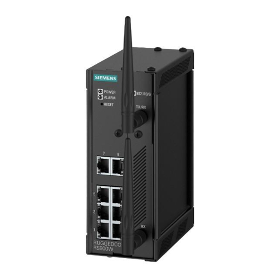
• CSA/UL 60950-1 safety approved to 85 °C (185 °F) Section 1.2 Description The RUGGEDCOM RS900W features various ports, controls and indicator LEDs on the front panel for connecting, configuring and troubleshooting the device. Figure 1: RUGGEDCOM RS900W 1. POWER LED 2. ALARM LED 3. RESET Button 4. [Optional] Copper (10/100Base-TX) or Fiber Optic (100Base-FX) Ethernet Ports ... - Page 13 Section 2.11, “Resetting Device”. Communication Ports Receive and transmit data, as well as provide access to the RUGGEDCOM ROS Web interface. For more information about the various ports available for the RUGGEDCOM RS900W, refer Chapter 3, Communication Ports. Failsafe Alarm Relay Latches to default state when a power disruption or other alarm condition occurs. For more information, refer to: •...
- Page 14 Chapter 1 RUGGEDCOM RS900W Introduction Installation Guide Description...
-
Page 15: Installing The Device
This product contains no user-serviceable parts. Attempted service by unauthorized personnel shall render all warranties null and void. Changes or modifications not expressly approved by Siemens Canada Ltd could invalidate specifications, test results, and agency approvals, and void the user's authority to operate the equipment. -
Page 16: General Procedure
Siemens also does not recommend using copper Ethernet ports to interface with devices in the field across distances that could produce high levels of ground potential rise (i.e. greater than 2500 V), during line-to-ground fault conditions. -
Page 17: Installing The Device In Hazardous Locations
Section 2.4 Installing the Device in Hazardous Locations The RUGGEDCOM RS900W is designed to comply with the safety standards for Class I, Division 2 hazardous locations where concentrations of flammable gases, vapors or liquids may be present, as opposed to normal operating environments. -
Page 18: Mounting The Device On A Din Rail
Chapter 2 RUGGEDCOM RS900W Installing the Device Installation Guide Forced airflow is not required. However, any increase in airflow will result in a reduction of ambient temperature and improve the long-term reliability of all equipment mounted in the rack space. -
Page 19: Mounting The Device To A Panel
Mounting the Device to a Panel For panel installations, the RUGGEDCOM RS900W can be equipped with panel adapters pre-installed on the top and bottom of the chassis. The adapters allow the device to be attached to a panel using screws. -
Page 20: Connecting The Failsafe Alarm Relay
Control of the failsafe relay output is configurable through ROS. One common application for this relay is to signal an alarm if a power failure occurs. For more information, refer to the ROS User Guide for the RUGGEDCOM RS900W. The following shows the proper relay connections. -
Page 21: Connecting Power
1. Normally Closed 2. Common 3. Normally Open Section 2.8 Connecting Power The RUGGEDCOM RS900W supports power input from a single high AC/DC or low DC power supply. IMPORTANT! • For 110/230 VAC rated equipment, an appropriately rated AC circuit breaker must be installed. - Page 22 Chapter 2 RUGGEDCOM RS900W Installing the Device Installation Guide CAUTION! Electrical hazard – risk of damage to equipment. Before testing the dielectric strength (HIPOT) in the field, remove the braided ground cable connected to the surge ground terminal and chassis ground.
-
Page 23: Connecting Low Dc Power
Section 2.8.2 Connecting Low DC Power RUGGEDCOM RS900W's equipped with 24 or 48 V power supply inputs feature reverse polarity protection and dual power supply inputs allowing the device to accept redundant connections to a single DC power supply. To connect a low DC power supply to the device, do the following: NOTE Torque all terminal connections to 0.6 N·m (5 lbf-in). -
Page 24: Connecting To The Device
Chapter 2 RUGGEDCOM RS900W Installing the Device Installation Guide ± ± ± ± Figure 8: Terminal Block Wiring - Dual DC Power Supply Inputs 1. Positive Terminal 2. Negative Terminal 3. Surge Ground Terminal 4. Braided Ground Cable Using a braided wire or other appropriate grounding wire, connect the surge ground terminal to the chassis ground connection. - Page 25 RUGGEDCOM RS900W Chapter 2 Installation Guide Installing the Device IMPORTANT! The serial console port is intended to be used only as a temporary connection during initial configuration or troubleshooting, and should only be used in a safe area (as defined by IEC 60079-0, Edition 6.0).
-
Page 26: Configuring The Device
Section 2.11 Resetting the Device The RUGGEDCOM RS900W can be reset (rebooted) using the RESET button. The RESET button is recessed and can only be reached using a pin or small screwdriver. To reset the device, quickly press and release the RESET button with a pin. -
Page 27: Communication Ports
RUGGEDCOM RS900W Chapter 3 Installation Guide Communication Ports Communication Ports The RUGGEDCOM RS900W can be equipped with various types of communication ports to enhance its abilities and performance. Figure 10: Port Assignment 1. Ports 1 to 6 2. Ports 7 and 8 3. Port 9 Port... -
Page 28: Copper Ethernet Ports
Section 3.1 Copper Ethernet Ports The RUGGEDCOM RS900W supports multiple 10/100Base-TX Ethernet ports that allow connection to standard Category 5 (CAT-5) unshielded twisted-pair (UTP) cables with RJ45 male connectors. The RJ45 receptacles are directly connected to the chassis ground on the device and can accept CAT-5 shielded twisted-pair (STP) cables. -
Page 29: Fiber Optic Ethernet Ports
RUGGEDCOM RS900W Chapter 3 Installation Guide Communication Ports Section 3.2 Fiber Optic Ethernet Ports Fiber optic Ethernet ports are available with either MTRJ (Mechanical Transfer Registered Jack), LC (Lucent Connector), SC (Standard or Subscriber Connector) or ST (Straight Tip) connectors. Make sure the Transmit (Tx) and Receive (Rx) connections of each port are properly connected and matched to establish a proper link. -
Page 30: Wireless Ethernet Ports
Section 3.3 Wireless Ethernet Ports The RUGGEDCOM RS900W supports an optional set of IEEE 802.11 compliant wireless Ethernet ports for accessing a Wireless Local Area Network (WLAN). Depending on the options chosen, the device is permitted for use in either North America (US), the European Union (EU), Australia (AU), or India (IN). -
Page 31: Channel Allocations For Ieee 802.11B/G
RUGGEDCOM RS900W Chapter 3 Installation Guide Communication Ports 63 mW (18 dBm) 802.11g 48 Mbps Data Rate 40 mW (16 dBm) 802.11g 54 Mbps Data Rate Receiver Sensitivity At Radio 802.11b 11 Mb @ -88 dBm/With Antenna: 11 Mb @ -91 dBm At Radio 802.11g 54 Mb @ -74 dBm/With Antenna: 54 Mb @ -77 dBm... - Page 32 Chapter 3 RUGGEDCOM RS900W Communication Ports Installation Guide Channel Allocations for IEEE 802.11b/g...
-
Page 33: Technical Specifications
RUGGEDCOM RS900W Chapter 4 Installation Guide Technical Specifications Technical Specifications This section provides important technical specifications related to the device. CONTENTS • Section 4.1, “Power Supply Specifications” • Section 4.2, “Failsafe Relay Specifications” • Section 4.3, “Copper Ethernet Port Specifications” • Section 4.4, “Fiber Optic Ethernet Port Specifications”... -
Page 34: Failsafe Relay Specifications
Chapter 4 RUGGEDCOM RS900W Technical Specifications Installation Guide Input Range Internal Maximum Power Power Supply Type Isolation Fuse Rating Consumption Minimum Maximum 37 VDC 72 VDC 3.15 A(T) 1.5 kVDC 10 W (T) denotes time-delay fuse. Power consumption varies based on configuration. -
Page 35: Fiber Optic Ethernet Port Specifications
To convert from peak to average, subtract 3 dBm. • Maximum segment length is greatly dependent on factors such as fiber quality, and the number of patches and splices. Consult a Siemens sales associate when determining maximum segment distances. Tx (dBm) -
Page 36: Operating Environment
Chapter 4 RUGGEDCOM RS900W Technical Specifications Installation Guide Section 4.5 Operating Environment Parameter Range Comments Ambient Operating Temperature -40 to 85 °C Measured from a 30 cm (12 in) radius surrounding the center of the (-40 to 185 °F) enclosure. Ambient Relative Humidity... -
Page 37: Dimension Drawings
RUGGEDCOM RS900W Chapter 5 Installation Guide Dimension Drawings Dimension Drawings NOTE All dimensions are in millimeters, unless otherwise stated. 65.3 116.59 7.87 Figure 17: Overall Dimensions... - Page 38 Chapter 5 RUGGEDCOM RS900W Dimension Drawings Installation Guide 134.1 13.64 101.6 11.2 78.74 120.65 Figure 18: Panel and DIN Rail Mount Dimensions...
-
Page 39: Certification
RUGGEDCOM RS900W Chapter 6 Installation Guide Certification Certification The RUGGEDCOM RS900W device has been thoroughly tested to guarantee its conformance with recognized standards and has received approval from recognized regulatory agencies. CONTENTS • Section 6.1, “Approvals” • Section 6.2, “EMC and Environmental Type Tests”... -
Page 40: Fcc
• Title 21 Code of Federal Regulations (CFR) – Chapter I – Sub-chapter J – Radiological Health Section 6.1.4 ISED This device is declared by Siemens Canada Ltd to meet the requirements of the following ISED (Innovation Science and Economic Development Canada) standard: • CAN ICES-3 (A)/NMB-3 (A) -
Page 41: Rohs
Certification Section 6.1.5 RoHS This device is declared by Siemens Canada Ltd to meet the requirements of the following RoHS (Restriction of Hazardous Substances) directives for the restricted use of certain hazardous substances in electrical and electronic equipment: • China RoHS 2... - Page 42 Chapter 6 RUGGEDCOM RS900W Certification Installation Guide Test Description Test Levels Severity Levels DC Power Ports ± 2 kV Line-to-Ground ± 1 kV Line-to-Line AC Power Ports ± 4 kV Line-to-Ground ± 2 kV Line-to-Line IEC 61000-4-6 Induced (Conducted) RFI...
-
Page 43: Environmental Type Tests
EMC Immunity Type Tests per IEEE 1613 NOTE The RUGGEDCOM RS900W meets Class 2 requirements for an all-fiber configuration and Class 1 requirements for copper ports. Class 1 allows for temporary communication loss, while Class 2 requires error-free and interrupted communications. - Page 44 Chapter 6 RUGGEDCOM RS900W Certification Installation Guide EMC and Environmental Type Tests...