Graco Husky 515 Instructions Manual
Air operated diaphragm pumps
acetal, polypropylene, and pvdf
model no. d51 acetal npt pumps*
model no. d52 polypropylene pumps
model no. d55 pvdf npt pumps
model no. d5a acetal bspt pumps*
model no. d5b polypropylene bspt pumps
model no. d5e pvdf
Hide thumbs
Also See for Husky 515:
- Instructions manual (18 pages) ,
- Instructions-parts list manual (12 pages) ,
- Instructions manual (8 pages)
Table of Contents
Advertisement
Instructions
Air–Operated
Diaphragm Pumps
For fluid transfer applications. For professional use only.
Only models marked with (*) are approved for use in European explosive atmosphere
locations.
100 psi (0.7 MPa, 7 bar) Maximum Fluid Working Pressure
100 psi (0.7 MPa, 7 bar) Maximum Air Input Pressure
ACETAL, POLYPROPYLENE, AND PVDF
Huskyt 515
Model No. D 5 1 _ _ _ Acetal NPT Pumps*
Model No. D 5 2 _ _ _ Polypropylene Pumps
Model No. D 5 5 _ _ _ PVDF NPT Pumps
Model No. D 5 A _ _ _ Acetal BSPT Pumps*
Model No. D 5 B _ _ _ Polypropylene BSPT Pumps
Model No. D 5 E _ _ _ PVDF BSPT Pumps
For Additional Models, see Table of Contents
ALUMINUM AND STAINLESS STEEL*
Huskyt 716
Model No. D 5 3 _ _ _ Aluminum NPT Pumps
Model No. D 5 4 _ _ _ Stainless Steel NPT Pumps
Model No. D 5 C _ _ _ Aluminum BSPT Pumps
Model No. D 5 D _ _ _ Stainless Steel BSPT Pumps
For Additional Models, see Table of Contents
*These models are
Patents Pending
Important Safety Instructions
Read all warnings and instructions in this manual.
Save these instructions.
Refer to the Pump Matrix on page 20 to determine
the model number of your pump.
certified.
308981ZAA
EN
9065A
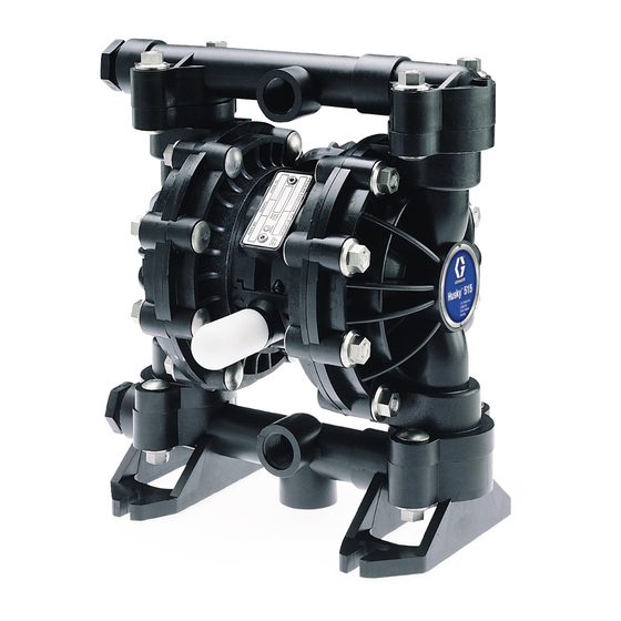
Husky 515
9246A
Husky 716
Advertisement
Table of Contents

Related Manuals for Graco Husky 515


Summary of Contents for Graco Husky 515
- Page 1 Model No. D 5 B _ _ _ Polypropylene BSPT Pumps Model No. D 5 E _ _ _ PVDF BSPT Pumps For Additional Models, see Table of Contents 9065A Husky 515 ALUMINUM AND STAINLESS STEEL* Huskyt 716 Model No. D 5 3 _ _ _ Aluminum NPT Pumps Model No.
-
Page 2: Table Of Contents
D Read all instruction manuals, tags, and labels before operating the equipment. D Use the equipment only for its intended purpose. If you are not sure, call your Graco distributor. D Do not alter or modify this equipment. Use only genuine Graco parts and accessories. - Page 3 WARNING TOXIC FLUID HAZARD Hazardous fluid or toxic fumes can cause serious injury or death if splashed in the eyes or on the skin, inhaled, or swallowed. D Know the specific hazards of the fluid you are using. D Do not lift a pump under pressure. If dropped, the fluid section may rupture. Always follow the Pressure Relief Procedure on page 10 before lifting the pump.
-
Page 4: Installation
Polypropylene: 150_ F (66_ C) Aluminum, stainless steel, PVDF: 225_ F (107_ C) These temperatures are based upon mechanical stress D Always use Genuine Graco Parts and Accessories. only and may be significantly altered by pumping certain chemicals. Consult engineering guides for chemical com- patibilities and temperature limits, or contact your Graco distributor. - Page 5 3. Connect remaining ends of tubes to external air signal, such as Graco’s Cycleflo (P/N 195264) or Cycleflo II (P/N195265) controllers. CAUTION NOTE: the air pressure at the connectors must be at least 30% of the air pressure to the air motor for the The pump exhaust air may contain contaminants.
- Page 6 Installation Fluid Pressure Relief Valve Air Exhaust Ventilation CAUTION Read Toxic Fluid Hazard on Some systems may require installation of a pressure page 3. relief valve at the pump outlet to prevent overpres- surization and rupture of the pump or hose. Read Fire and Explosion See Fig.
- Page 7 Installation ABOVE-GROUND TRANSFER INSTALLATION Pump Bleed-type master air valve (required for pump) Electrically conductive air supply line Air line quick disconnect Master air valve (for accessories) Air line filter G Pump air regulator Fluid drain valve (required) Fluid regulator (optional) Electrically conductive fluid supply hose Fluid suction line...
- Page 8 To tion Fire and Explosion Hazard on page 3. order a ground wire and clamp, order Part No. The acetal Husky 515 pump contains stainless 222011. steel fibers, which makes the wetted parts conduc- D Air and fluid hoses: Use only electrically conductive tive.
- Page 9 Installation Changing the Orientation of the Fluid Inlet Torque to 80 to 90 in-lb (9 to 10 NSm). See and Outlet Ports (Husky 515) Torque Sequence, page 27. You can change the orientation of the fluid inlet and outlet ports by repositioning the manifolds. For Husky 515, see Fig.
-
Page 10: Operation
Operation Pressure Relief Procedure 5. Place the suction tube (if used) in the fluid to be pumped. WARNING NOTE: If the inlet fluid pressure to the pump is more than 25% of the outlet working pressure, the ball check PRESSURIZED EQUIPMENT HAZARD valves will not close fast enough, resulting in inefficient The equipment stays pressurized until pressure is pump operation. -
Page 11: Maintenance
Maintenance Lubrication Tightening Threaded Connections The air valve is lubricated at the factory to operate Before each use, check all hoses for wear or damage without additional lubrication. If you want to provide and replace as necessary. Check to be sure all additional lubrication, remove the hose from the pump threaded connections are tight and leak-free. -
Page 12: Troubleshooting
Troubleshooting Read Pressure Relief Procedure on page 10, and relieve the pressure before you check or service the equipment. Check all possible problems and causes before disassembling the pump. PROBLEM CAUSE SOLUTION Pump will not cycle, or cycles once Air valve is stuck or dirty. Use filtered air. -
Page 13: Service
Service Air Valve (Husky 515 and Husky 716 Pumps) NOTE: Air Valve Repair Kit 241657 is available. Parts included in the kit are marked with a dagger ({) in Fig. 6 and in the Parts Drawings and Lists. A tube of general purpose grease 111920 is supplied in the kit. Service the air valve as follows. - Page 14 Service Ball or Duckbill Check Valves Inlet and Outlet for Pumps with Duckbill Check Valves NOTE: Fluid Section Repair Kit D05XXX is available. See page 21 to order the correct kit for your pump. Parts included in the kit are marked with a double Pumps with duckbill check valves are shipped with the dagger (}) in Fig.
- Page 15 Service Husky 515 Husky 716 Torque to 80 to 90 in-lb (9 to 10 N-m). See Torque Sequence, page 27. 9067A Fig. 7 Torque to 80 to 90 in-lb (9 to 10 N-m). See Torque Sequence, page 27. 9081A Fig. 8...
- Page 16 Service Diaphragms (Husky 515) NOTE: Fluid Section Repair Kit D05XXX is available. See page 21 to order the correct kit for your pump. Parts included in the kit are marked with a double dagger (}) in Fig. 9 and in the Parts Drawings and Lists. General purpose grease 111920 and Adhesive 113500 are supplied in the kit.
- Page 17 Service Diaphragms (Husky 515) Included in Fluid Section Repair Kit D05XXX Install with lips facing out of center housing (11). Torque to 35 to 45 in-lb (4.0 to 5.1 N-m). Apply grease. The words “AIR SIDE” on diaphragms (and on backup diaphragms required on PTFE models) must face toward diaphragm shaft (15).
- Page 18 Service Diaphragms (Husky 716) NOTE: Fluid Section Repair Kit D05XXX is available. See page 21 to order the correct kit for your pump. Parts included in the kit are marked with a double dagger (}) in Fig. 10 and in the Parts Drawings and Lists. General purpose grease 111920 and Adhesive 113500 are supplied in the kit.
- Page 19 Service Diaphragms (Husky 716) Included in Fluid Section Repair Kit D05XXX Install with lips facing out of center housing (11). Torque to 35 to 45 in-lb (4.0 to 5.1 N-m). Apply grease. The words “AIR SIDE” on diaphragms (and on backup diaphragms used on PTFE models) must face toward diaphragm shaft (15).
-
Page 20: Husky 515 And Husky 716 Pump Matrix
Husky 515 and Husky 716 Pump Matrix Your Model No. is marked on the pump’s serial plate. To determine a pump Model No. from the following matrix, select the six digits that describe the pump, working from left to right. The first digit is always D, designating Husky diaphragm pumps. -
Page 21: Husky 515 And 715 Additional Pumps
Same as the D54311 pump, but tested for use with moisture–sensitive materials. Model 24B674, 716 pump Same as the D54311 pump Husky 515 and Husky 716 Repair Kits NOTE: Order Repair Kits separately. To order the Air Valve Repair Kit, order Part No. 241657. -
Page 22: Husky 515 And Husky 716 Common Parts
Husky 515 and Husky 716 Common Parts See the Pump Matrix on page 20 for an explanation of the Matrix Column and the Digit. Air Motor Parts List (Matrix Column 2) 201} 192138 SPACER 202} 192137 VALVE, duckbill Ref. Digit Part No. -
Page 23: Husky 515 Parts Drawing
Husky 515 Parts Drawing Included in Air Valve Repair Kit 241657 Included in Fluid Section Repair Kit D05XXX grounding screw These parts are unique to the remote oper- (acetal pump only) ated air motor. 7{ 2{ }416 9064B 308981... -
Page 24: Husky 515 Fluid Section Parts List
See the Pump Matrix on page 20 for an explanation of the Matrix Column and the Digit. See page 22 for Air Motor Parts List (Matrix Column 2) Husky 515 Fluid Section Parts List (Matrix Column 3) Acetal Pumps Polypropylene Pumps... -
Page 25: Husky 716 Parts Drawing
Husky 716 Parts Drawing Included in Air Valve Repair Kit 241657 Included in Fluid Section Repair Kit D05XXX These parts are unique to the remote operated air motor. Grounding Detail 9070A 308981... -
Page 26: Husky 716 Fluid Section Parts List
Husky 716 Fluid Section Parts List See the Pump Matrix on page 20 for an explanation of the Matrix Column and the Digit. See page 22 for Air Motor Parts List (Matrix Column 2) Husky 716 Fluid Section Parts List (Matrix Column 3) Aluminum Pumps Stainless Steel (sst) Pumps Digit: 3 (NPT) -
Page 27: Torque Sequence
Torque Sequence Always follow torque sequence when instructed to torque fasteners. Husky 515 Husky 716 1. Left/Right Fluid Covers 1. Left/Right Fluid Covers Torque bolts to 80–90 in–lb (9–10 NSm) Torque bolts to 80–90 in–lb (9–10 NSm) 1 1 1 1... -
Page 28: Husky 515 Technical Data
Husky 515 Technical Data Maximum fluid working pressure ......... . . -
Page 29: Dimensions
Husky 515 Dimensions FRONT VIEW 1/2 npt(f) or bspt(f) Fluid Outlet * 4.70 in. 5.01 in. (119 mm) (127 mm) 1/4 npt(f) Air Inlet * Pumps with duckbill check valves are shipped with the inlet manifold on top and the outlet manifold on the bottom. -
Page 30: Husky 716 Technical Data
*These temperatures are based on mechanical stress only and may be altered significantly by pumping certain chemicals. Consult engineering guides for chemical compatibilities and temperature limits, or contact your Graco distributor. Santoprener is a registered trademark of the Monsanto Company. -
Page 31: Dimensions
Husky 716 Dimensions FRONT VIEW 4.25 in. 4.44 in. 3/4 npt(f), bspt(f), or bspp(f) (108.0 mm) (112.8 mm) * Pumps with duckbill Fluid Outlet * check valves are shipped with the inlet manifold on 1/4 npt(f) Air Inlet top and the outlet manifold on the bottom. -
Page 32: Husky 515 And Husky 716 Performance Charts
Husky 515 and 716 Performance Charts Fluid Outlet Pressure Test Conditions: Pump tested in water with inlet submerged. (0.7, 7) Fluid Pressure Curves A at 100 psi (0.7 MPa, 7 bar) air pressure B at 70 psi (0.48 MPa, 4.8 bar) air pressure (0.55, 5.5) - Page 33 Husky 515 and 716 Performance Charts Air Consumption Test Conditions: Pump tested in water with inlet submerged. (0.84) È È È È È Air Consumption Curves È È È È È È È È È È È A at 100 psi (0.7 MPa, 7 bar) air pressure È...
-
Page 34: Graco Standard Warranty
With the exception of any special, extended, or limited warranty published by Graco, Graco will, for a period of five years from the date of sale, repair or replace any part of the equipment determined by Graco to be defec- tive.