Table of Contents
Advertisement
Quick Links
Advertisement
Table of Contents
Troubleshooting

Related Manuals for Henny Penny PFG-691


Summary of Contents for Henny Penny PFG-691
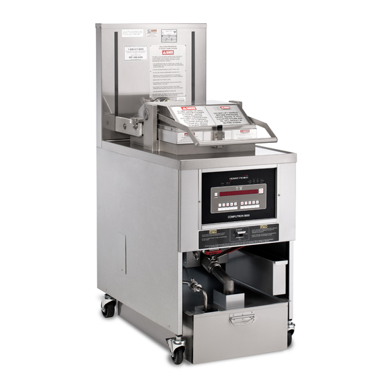
- Page 1 Henny Penny Pressure Fryer Model PFG-691 TECHNICAL MANUAL...
- Page 3 Do not obstruct the flow of combustion and ventilation air. Adequate clearance must be left all around appliance for sufficient air to the combustion chamber. The Model PFG-691 pressure fryer is equipped with a continuous pilot. But fryer cannot be operated without electric power. Fryer will automatically return to normal operation when power is restored.
- Page 4 Model 691 HENNY PENNY 8 HEAD GAS PRESSURE FRYER SPECIFICATIONS Height 61” (155 cm) Width 24” (61 cm) Depth 41¾” (106 cm) Floor Space Approximately 7 sq. ft. (0.65 sq. m.) Pot Capacity 8 Head of chicken (32 lbs.) (14.4 kg.) 130 lbs.
-
Page 5: Table Of Contents
Preventive Maintenance ................. 2-1 High Temperature Limit Control ..............2-1 Power/Pump Switch ..................2-4 Temperature Probe Replacement ..............2-5 Complete Control Panel - Henny Penny ............2-6 Pressure Regulation ..................2-6 Tilting the Lid Upright ................... 2-7 2-10 Clean the Nylatrons ..................2-7 2-11 Reversing the Lid Gasket ................ - Page 6 Model 691 TABLE OF CONTENTS Section Page Section 3. PARTS INFORMATION ..................... 3-1 Introduction ....................3-1 Genuine Parts ....................3-1 When Ordering Parts ..................3-1 Prices ......................3-1 Delivery ......................3-1 Warranty ......................3-1 Recommended Spare Parts for Distributors ........... 3-1 Section 4.
-
Page 7: Section 1. Troubleshooting
Model 691 SECTION 1. TROUBLESHOOTING 1-1. INTRODUCTION This section provides troubleshooting information in the form of an easy-to-read table. If a problem occurs during the first operation of a new fryer, recheck the installation per the Installation Section of the Operator’s Manual. -
Page 8: Troubleshooting
Model 691 1-3. TROUBLESHOOTING To isolate a malfunction, proceed as follows: Clearly define the problem (or symptom) and when it occurs. Locate the problem in the Troubleshooting table. Review all possible causes. Then, one at a time, work through the list of corrections until the problem is solved. Refer to the maintenance procedures in the Maintenance Section to safely and properly make the checkout and repair needed. - Page 9 Model 691 1-3. TROUBLESHOOTING (Continued) Problem Cause Correction COOKING SECTION Product color not correct: • • A. Too dark Temperature too high Check temperature setting in the program mode; see programming section of Operator’s Manual • • Faulty temperature probe Remove and replace tempera- ture probe •...
- Page 10 Model 691 1-3. TROUBLESHOOTING (Continued) Problem Cause Correction COOKING SECTION (Continued) Improper separation of the Load product into basket • • D. Spotted product product properly Breading not uniform on • • Sift breading regularly • the product Separate product during breading Burned breading particles •...
- Page 11 Model 691 1-3. TROUBLESHOOTING (Continued) Problem Cause Correction COOKING SECTION (Continued) • • D. Rancid taste Shortening too old Replace shortening and follow recommended care and use of shortening Infrequent filtering • • Replace shortening and follow recommended care and use of shortening •...
- Page 12 Model 691 1-3. TROUBLESHOOTING (Continued) Problem Cause Correction POWER SECTION • • With switch in Open circuit Check to see that unit is POWER position, plugged in • the fryer is completely Check the breaker or fuse inoperative at supply box •...
- Page 13 Model 691 1-3. TROUBLESHOOTING (Continued) Problem Cause Correction PRESSURE SECTION (Continued) Place proper quantity of • • Pressure does not Not enough product in fryer build or product not fresh fresh product within frypot to generate steam • • Metal shipping spacer not Remove shipping spacer;...
- Page 14 Model 691 1-3. TROUBLESHOOTING (Continued) Problem Cause Correction HEATING OF SHORTENING SECTION Blown fuse or tripped • • Shortening will Reset breaker or replace fuse not heat (“E-20”) circuit breaker at supply box or control panel Blown fuse in PC board •...
- Page 15 Model 691 1-3. TROUBLESHOOTING (Continued) Problem Cause Correction HEATING OF SHORTENING SECTION (Continued) Increase supply line size • • Heating of Supply line too small; low shortening too gas volume Refer to installation slow instructions Improper ventilation • • Refer to installation system instructions •...
- Page 16 Model 691 1-3. TROUBLESHOOTING (Continued) Problem Cause Correction SHORTENING FOAMING/DRAINING SECTION • • Foaming or boiling Water in shortening At end of cook cycle, over of drain shortening and clean shortening frypot; add fresh shortening • • Condensation line clogged Remove and clean conden- sation line Improper or bad shortening...
-
Page 17: Error Codes
Let unit cool (15-20 min.), reset high limit by manually push- “E-10” ing up on red reset button; if high limit does not reset, high limit must be replaced; call Henny Penny’s Service Dept. “E-15” Drain switch Close the drain using the drain valve handle; if display still shows “E-15”, call Henny Penny’s Service Department... - Page 18 Model 691 1-4. ERROR CODES (Continued) DISPLAY CAUSE PANEL BOARD CORRECTION “E-41” Programming Turn switch to OFF position, then back to ON; if display failure shows “E-41”, the control should be re-initialized (see Pro- gramming section); if the error code persists, replace the control panel “E-46”...
-
Page 19: Maintenance
Model 691 SECTION 2. MAINTENANCE 2-1. INTRODUCTION This section provides procedures for the checkout and replace- ment of the various parts used within the fryer. Before replacing any parts, refer to the Troubleshooting Section. It will aid you in determining the cause of the malfunction. 2-2. - Page 20 Model 691 2-4. HIGH TEMPERATURE LIMIT CONTROL (Continued) Before replacing a high temperature limit control, check to see Checkout that its circuit is closed. The shortening temperature must be below 380°F (193°C) to accurately perform this check. 1. Remove electrical power supplied to the fryer. To avoid electrical shock or property damage, move the power switch to OFF and disconnect main circuit breaker, or unplug cord at wall receptacle.
- Page 21 Model 691 2-4. HIGH TEMPERATURE Drain shortening from the frypot and discard. A substance LIMIT CONTROL in the tube could contaminate the shortening. (Continued) Remove control panel. Loosen small inside screw nut on capillary tube. Remove capillary bulb from bulb holder inside the frypot. Straighten the capillary tube.
-
Page 22: Power/Pump Switch
Model 691 The POWER/PUMP switch is a three-way rocker switch with a 2-5. POWER/PUMP SWITCH center OFF position. With the switch in the POWER position, the fryer will operate. With the switch in the PUMP position, the filter pump will operate, but the unit will not heat. To avoid electrical shock or property damage, move the power switch to OFF and disconnect main circuit breaker, or unplug cord at wall receptacle. -
Page 23: Temperature Probe Replacement
Model 691 2-6. TEMPERATURE PROBE The temperature probe relays the actual shortening temperature to the control. If it becomes disabled, “E06” will show in the display. REPLACEMENT Also, if the temperature is out of calibration more than 10°F, or 10°C, the temperature probe should be replaced. An Ohm check can be performed also. -
Page 24: Complete Control Panel - Henny Penny
4. Install a new control panel. 2-8. PRESSURE REGULATION The Henny Penny fryer uses pressure as one of the components of the cooking process. Once the lid is sealed to the frypot and the solenoid valve closes, a deadweight valve maintains the correct pressure in the frypot. -
Page 25: Tilting The Lid Upright
(See photo at left.) 2-10. CLEAN THE NYLATRONS 1. Spray Henny Penny biodegradable, food safe, foaming degreaser (part no. 12226) on Nylatrons. 2. Raise lid up and down several times to spread degreaser. -
Page 26: Reversing The Lid Gasket
Model 691 2-11. REVERSING THE LID The gray rubber gasket surrounding the inside of the lid is GASKET designed to be reversed. Because of heat expansion and the pressure used for the cook- ing process, the gasket is constantly under extreme stress. Reversing the lid gasket will help to ensure that the fryer will not lose pressure through leakage. -
Page 27: Lid Counterweight Cables
Model 691 2-12. LID COUNTERWEIGHT The lid counterweight in the back of the fryer balances the CABLES weight of the lid system to allow easier opening and closing of the lid. The weight has two cables attached to it, and weighs about 150 lbs. - Page 28 Model 691 2-12. LID COUNTERWEIGHT 9. Remove the Allen head bolts securing the stabilizer bracket CABLES (Continued) and remove the bracket. 10. Remove the bolts and spacers securing the pulley bracket, and pull bracket back, to allow access to cable bracket. 11.
-
Page 29: Pressure Pads
Model 691 2-13. PRESSURE PADS The pressure pads are plastic strips that the lid cam presses against to seal the lid. They are located on top of the shims. 1. Raise the lid. 2. Remove the four screws securing the lid cover and remove cover. -
Page 30: Lid Adjustment
Model 691 If steam leaks out from around the lid gasket, the pressure pads 2-14. LID ADJUSTMENT could be worn or broken. If the pressure pad is worn, but not broken, it can be reversed 180 degrees, and the other end of the pad used. - Page 31 Model 691 2-15. SOLENOID VALVE-ABOVE COUNTER (Continued) Replacement 1. Remove the Tru-Arc retaining clip on top of the coil housing. 2. Remove the cover. 3. If only the coil is to be replaced, disconnect the two coil wires at the wire nuts in the coil housing. Remove the coil, insert new coil, and connect the wires at the wire nuts.
- Page 32 Model 691 2-15. SOLENOID VALVE-ABOVE 5. A repair kit (Part No. 17120) is available if any of the seals must be replaced. If any one seal is defective, they all COUNTER (Continued) should be replaced. Solenoid body must be removed from the fryer for replacement of seals.
-
Page 33: Solenoid Valve- Under Counter
Model 691 2-16. SOLENOID VALVE- This is an electromechanical device that causes pressure to be UNDER COUNTER held in the frypot. The solenoid valve closes at the beginning of the cook cycle and opens automatically at the end of the cook cycle. - Page 34 Model 691 5. If the core-disc assembly is sticking due to buildup of 2-16. SOLENOID VALVE-UNDER COUNTER (Continued) shortening, breading, and food particles, proceed with the following steps: a. Unscrew the solenoid bonnet assembly from solenoid valve body. b. Remove the solenoid bonnet assembly and bonnet gasket.
-
Page 35: Deadweight Valve
Model 691 2-16. SOLENOID VALVE-UNDER 13. Wet O-ring around seat with water and insert O-ring assembly (flat side first) in valve through “IN” side of COUNTER (Continued) body. Use an eraser end of pencil and press in the Teflon seal until it snaps into place. BE CAREFUL NOT TO MAR OR NICK THE SEAT. -
Page 36: Removal Of Safety Valve
Model 691 2-17. DEADWEIGHT VALVE (Continued) DO NOT PULL THE RING ON THE SAFETY RELIEF VALVE. HOT STEAM WILL BE RELEASED AND SEVERE BURNS WILL RESULT. ORIFICE WEIGHT 1. At the end of each day’s usage of the fryer, the deadweight valve must be cleaned. -
Page 37: Pressure Gauge
Model 691 2-18. REMOVAL OF SAFETY VALVE (Continued) Do not use a pipe wrench. Use thread sealant sparingly 2. Use a wrench to loosen the valve from the pipe tee; turn counterclockwise to remove. 3. Clean the inside of the pipe tee with hot water. Turn the safety relief valve towards the rear of the fryer when reinstalling safety relief valve. -
Page 38: Gas Control Valve
Model 691 2-20. GAS CONTROL VALVE The gas control valve sends regulated gas to burners when the controller calls for heat. The control valve can be turned on or off. In the ON position, and the power switch on, a spark ignitor lights a standing pilot, and when the control calls for heat, the valve is opened and the burners are ignited. - Page 39 Model 691 2-20. GAS CONTROL VALVE (Continued) 4. Remove left side panel. 5. Remove control panel. 6. Unscrew nut from inlet line from the control valve. 7. Remove the bracket from behind the control valve. 8. Remove pilot light tube from control valve. 9.
-
Page 40: Blower Assembly
Model 691 2-21. BLOWER ASSEMBLY The blower motor circulates air into the burner area to create the correct heat for the fryer. If the blower fails, a sensor will shut the power control valve down. 1. Remove the electrical power supplied to the unit. To avoid electrical shock or property damage, move the power switch to OFF and disconnect main circuit breaker, or unplug cord at wall receptacle. -
Page 41: Transformer
Model 691 2-21. BLOWER ASSEMBLY (Continued) 5. Remove the flue. 6. Disconnect wires at junction box. 7. Remove the blower from the plate. 8. Replace new blower in reverse order of procedures. 2-22. TRANSFORMER The transformer reduces the voltage down to accommodate those components with low voltage. -
Page 42: Airflow Switch
Model 691 The airflow switch senses the flow of air coming from the 2-23. AIRFLOW SWITCH blower. If the airflow is reduced below a set amount, the switch will cut power to the control valve, which shuts the burners down. Replacement 1. -
Page 43: Drain Microswitch
Model 691 Upon pulling out on drain handle, the microswitch should be 2-24. DRAIN MICROSWITCH activated and unit will not heat, but when handle is pushed back, unit should operate properly. The bracket on micro- switch is slotted so it can be adjusted backward or forward. 1. -
Page 44: Drain Valve And Extension
Model 691 2-25. DRAIN VALVE The drain valve opens when the drain valve handle is pulled AND EXTENSION out and drains the shortening out of the pot. 1. Using a 3/8” socket, remove the nuts securing the drain switch bracket, and pull the bracket from the studs. 2. -
Page 45: Air Valve
Model 691 2-26. AIR VALVE The air valve allows circulation of the shortening in the frypot to keep the shortening at a uniform temperature. 1. Remove electrical power supplied to the unit. To avoid electrical shock or property damage, move the power switch to OFF and disconnect main circuit breaker, or unplug cord at wall receptacle. -
Page 46: Cleaning The Dilution Box
Model 691 2-27. CLEANING THE Clean the dilution box monthly to ensure the unit operates efficiently and without failures. DILUTION BOX 1. Make sure unit is off, and close and lock the lid. Lid should be in locked down position. Failure to do so could result in personal injury. -
Page 47: Ignition Modules
OFF and disconnect main circuit breaker, or unplug cord at wall receptacle. 2. Remove the control panel as discussed in the Complete Control Panel-Henny Penny Section. 3. Remove the condensation drain pan. 4. Using a Phillip’s head screwdriver, remove the screws securing the module cover and remove the cover. -
Page 48: Ignitor Assembly
SUPPLY LINE TO FRYER. 2. Remove the control panel as discussed in the Complete Control Panel-Henny Penny Section. 3. Disconnect the 1/4” gas line fitting from the pilot assembly. 4. Follow the wire from the spark ignitor to the module, and remove the wire from the module. -
Page 49: Flame Sensor Assembly
2. Remove the control panel as discussed in he Complete Control Panel-Henny Penny Section. 3. Pull the wire off the terminal of the flame sensor. 4. Using Phillips head screwdriver, remove the screw securing the flame sensor assembly, and remove assembly from unit. -
Page 50: Nylatron Strips Replacement
Model 691 2-33. NYLATRON STRIPS REPLACEMENT 1. Raise the lid and remove the retention ring from one end of the lid pin. 2. Slide the lid pin from unit. 3. Lift the lid from unit. The lid weighs 80 lbs (36 kg). Take care when lifting lid to prevent personal injury. -
Page 51: Lubricating Lid Rollers
Model 691 2-33. NYLATRON STRIPS REPLACEMENT (CONTD) 9. Lift the front shroud up and out, over the arm of the lid. 10. Thread the new nylatron strip through the track in the front shroud. 11. Lining up the holes in the strips, fit the front shroud back over the lid arms. - Page 52 Model 691 SN: FH001JC & ABOVE Aug. 2004 2-34...
- Page 53 Model 691 SN: FH001JC & ABOVE Aug. 2004 2-35...
- Page 54 Model 691 SN: FH001JC & ABOVE Aug. 2004 2-36...
- Page 55 Model 691 BELOW SN: FH001JC March 2004 2-37...
- Page 56 Model 691 BELOW SN: FH001JC March 2004 2-38...
- Page 57 Model 691 BELOW SN: FH001JC March 2004 2-39...
- Page 58 Model 691 BELOW SN: FH001JC March 2004 2-40...
- Page 59 During this time, any frypot that fails due to manufacturing or workmanship issues will be replaced at no charge for parts, labor, or freight. Henny Penny will either install a new frypot at no cost or provide a new or reconditioned replacement fryer at no cost.
-
Page 61: Section 3. Parts Information
This section lists the replaceable parts of the Henny Penny Model 691 fryer. Use only genuine Henny Penny parts in your fryer. Using a part 3-2. GENUINE PARTS of lesser quality or substitute design may result in damage to the unit or personal injury. - Page 62 Model 691 FIGURE 3-1. FRAME & COVER ASSEMBLY Oct. 2004...
- Page 63 Model 691 Figure & Item No. Part No. Description Qty. FRAME & COVER ASSEMBLY 39796 WELDMENT – CONTROL PANEL FRONT ......53669 GUARD – POWER SWITCH ..........√ 29898 SWITCH – POWER ..............70591 REAR SHROUD – ACCESS ASSEMBLY ......58258 .
- Page 64 Model 691 Figure & Item No. Part No. Description Qty. CONTROL PANEL √ 1 65279RB CONTROL ASSY – 691 (S/N FH001JC AND HIGHER) ....√ 1 14465 CONTROL ASSY KIT, 120V, 691 (BELOW S/N FH001JC) ... √ 1 14466 CONTROL ASSY KIT, 220-240V, 691 (BELOW S/N FH001JC) ..√ 1 14636 KIT-691 to Giant of Carlisle C8000-60HZ (BELOW S/N FH001JC)
- Page 65 Model 691 Figure & Item No. Part No. Description Qty. ELECTRICAL CONTROLS √ 1 60207 TRANSFORMER ASSY – 120V ............. √ 60536 TRANSFORMER ASSY -- 24V/230V ..........SC03-005 SCREW .................... √ 140049 KIT, RELAY, 120V (SN: AP0903010 & below) ......√...
- Page 66 Model 691 Figure & Item No. Part No. Description Qty. FRYPOT COVERS & INSULATION 52799 ASSY-INSUL/LFT. C/CHAMBER ........52041 INSULATION-C/CHAMBER MOUNTIN ......52798 ASSY-INSUL/RT. C/CHAMBER .......... 52800 ASSY-INSUL/REAR C/CHAMBER ........52038 INSULATION-LOWER CHAMBER DUC ......52040 INSULATION-REAR C/CHAMBER ........51897 INSULATION-LOWER CHAMBER COV ......
- Page 67 Model 691 Figure & Item No. Part No. Description Qty. INSULATION COVERS WA02-001 WASHER – INSULATION 1-1/2” DIA......... 51763 INSULATION COVER – LEFT ..........51892 INSULATION – C/CHAMBER SIDE ........51765 INSULATION COVER – RIGHT .......... 51759 INSULATION COVER – REAR..........51893 INSULATION –...
- Page 68 Model 691 FIGURE 3-6. LID & COVER ASSEMBLY March 2007...
- Page 69 Model 691 Figure & Item No. Part No. Description Qty. LID & COVER ASSEMBLY 35792 LID INSTRUCTION LABEL ..........35675 FILLER-LID ................35243 COVER-MAIN LID ............... 35413 PLATE-TRIP ................√ 52627 PRESSURE PAD ASSY............49852 . BUSHING-PRESSURE PAD ..........SC01-204 .
- Page 70 Model 691 FIGURE 3-7. DRAIN PAN & FILTER ASSEMBLY Aug. 2010 3-10...
- Page 71 Model 691 Figure & Item No. Part No. Description Qty. DRAIN PAN & FILTER ASSEMBLY 52194 CRUMB CATCHER (OPTIONAL) (REQUIRES ITEM 10) ..03204 CRUMB CATCHER BASKET W/HANDLE (OPTIONAL) ..(FITS INSIDE FRYPOT) 21010 . “COLD ZONE” CRUMB CATCHER BASKET ASSEMBLY .. 24429 .
- Page 72 Model 691 FIGURE 3-8A. FILTER PUMP ASSEMBLY (SN: LH028JC & BELOW) Aug. 2010 3-12...
- Page 73 Model 691 Figure & Item No. Part No. Description Qty. 3-8A FILTER PUMP ASSEMBLY (SN: LH028JC & BELOW) 18107 CONDUIT CONNECTOR 3/8 X 90 ........... 54484 BLOWER/PUMP – FLEXIBLE CONDUIT ........√ 17476 PUMP SEAL KIT ................18105 ANTI SHORT 3/8 INCH ..............18644 CONDUIT CONNECTOR 3/8 X 90 ..........
- Page 74 Model 691 FIGURE 3-8B. FILTER PUMP ASSEMBLY (SN: LH029JC & ABOVE) Oct. 2004 3-14...
- Page 75 Model 691 Figure & Item No. Part No. Description Qty. 3-8B FILTER PUMP ASSEMBLY (SN: LH029JC & ABOVE) 18107 CONDUIT CONNECTOR 3/8 X 90 ..........54484 BLOWER/PUMP – FLEXIBLE CONDUIT ......... √ 17476 PUMP SEAL KIT ................18105 ANTI SHORT 3/8 INCH ............... 18644 CONDUIT CONNECTOR 3/8 X 90 ..........
- Page 76 Model 691 Figure & Item No. Part No. Description Qty. FILTER PUMP ASSEMBLY 64218 PUMP SUBASSY 8GPM √ 1 23468 ROTOR - 8 GPM PUMP ........... √ 2 23467 BODY - 8 GPM PUMP ..........√ 3 17456 PUMP SHIELD ............√ 4 23470 CAP - 8 GPM PUMP ..........
- Page 77 Model 691 FIGURE 3-10. GAS BURNER ASSEMBLY May 2005 3-17...
- Page 78 Model 691 Figure & Item No. Part No. Description Qty. 3-10 GAS BURNER ASSEMBLY 56990-01* BURNER ASSY – NATURAL ............56990-02* BURNER ASSY – LP ..............56990-03* BURNER ASSY – NATURAL CE ..........56990-04* BURNER ASSY – LP CE .............. 56990-05* BURNER ASSY –...
- Page 79 Model 691 FIGURE 3-11. GAS PIPING & CONTROLS Dec. 2009 3-19...
- Page 80 Model 691 Figure & Item No. Part No. Description Qty. 3-11 GAS PIPING & CONTROLS FP01-117 ELBOW ....................FP05-010 FITTING 3/8 TUBE TO 1/4 NP ............65173 MANIFOLD TUBE – LEFT .............. 65173 MANIFOLD TUBE – RIGHT............FP01-115 NIPPLE – 3/8 to 1/2 NP..............FP01-112 1/2 NPT FEMALE PIPE TEE B.I.
- Page 81 Model 691 Figure & Item No. Part No. Description Qty. 3-12 BURNER TUBES 54480 BRACKET ASSY – HIGH LIMIT SENSING BULB ....62051 CLIP – SPREADER – HEAT TUBE ..........53670 SPACER – HIGH LIMIT ............... √ 16738 450 HIGH LIMIT – NON CE ............√...
- Page 82 Model 691 Figure & Item No. Part No. Description Qty. 3-13 CARRIER AND RACKS 62183 CARRIER ASSY ............44782 RACK HALF SIZE - 8 HEAD FRYER ....... 67461 RACK HALF SIZE - COATED ........36404 WIRE BASKET - GM 8 HEAD ........36374 ASSY - BASKET HANDLE WELD ......
- Page 83 Model 691 Figure & Item No. Part No. Description Qty. 3-14 VACUUM SWITCH 60202 TUBE-VACUUM SWITCH ............√ 14240 KIT, VACUUM SWITCH – VERTICAL........√ 72514 • VACUUM SWITCH-VERTICAL ..........SC03-005 • SCREW ..................√ recommended parts * not shown Aug. 2010 3-23...
- Page 84 Model 691 FIGURE 3-15. DEADWEIGHT & SOLENOID ASSY (SN: AP0802029 & ABOVE) Aug. 2010 3-24...
- Page 85 Model 691 Figure & Item No. Part No. Description Qty. 3-15 DEADWEIGHT & SOLENOID ASSY (SN: AP0802029 & ABOVE) √ 1 16910 PRESSURE GAUGE..........√ 2 59742 RELIEF VALVE ASSY ..........ELBOW, STREET, ½ X ½, 90 DEGREE ....FP01-127 FP01-063 REDUCER, ½...
- Page 86 Model 691 Figure & Item No. Part No. Description Qty. 3-16A STEAM BOX & HOSE ASSY (SN: AP0802029 & UP) TUBE, DW TO EXHAUST STACK SS ......35686 MS01-297 HOSE CLAMP, SS - .500 – 1.062 DID ......70569 TUBE, EXHAUST CONNECT ........35696 WELDMENT, STEAM EXHAUST BOX LID .....
- Page 87 Model 691 FIGURE 3-16B. STEAM BOX & HOSE ASSEMBLY (SN: AP0802028 & BELOW) Aug. 2010 3-27...
- Page 88 Model 691 Figure & Item No. Part No. Description Qty. 3-16B STEAM BOX & HOSE ASSEMBLY (SN: AP0802028 & BELOW) 56335 BRACKET – CONDENSATE BOX ..........21878 TUBING – STEAM EXHAUST ............42508 TUBING – STEAM EXHAUST-UNITS BUILT BEFORE 8/98 ..51748 CONDENSATE DRAIN HOSE ............
- Page 89 Model 691 FIGURE 3-17. FLUE ASSEMBLY & BLOWER SN: AP0802028 & BELOW Dec. 2009 3-29...
- Page 90 Model 691 Figure & Item No. Part No. Description Qty. 3-17 FLUE ASSEMBLY & BLOWER (SN: AP0802028 & BELOW) 55681 FLUE ASSY – WELDMENT ............55783 BRACKET – FLUE RETAINING ..........SC03-005 SCREW SD #8 X 1/2 PH PHD ............√...
- Page 91 Model 690 Model 691 FIGURE 3-16. FLUE ASSEMBLY & BLOWER FIGURE 3-18. FLUE ASSEMBLY & BLOWER SN: AP0802029 & ABOVE SN: AP0802029 & ABOVE 3-30 Aug. 2010 3-31...
- Page 92 Model 691 Figure & Item No. Part No. Description Qty. 3-18 FLUE ASSEMBLY AND BLOWER (SN: AP0802029 & ABOVE) 70582 FLUE ASSY – WELDMENT ............SC02-041 #8-32 X 7/16 PH IND XTRNL TRX ..........NS02-002 NUT KEPS 1/4-20 C ..............√...
- Page 93 Model 691 FIGURE 3-18. SOLENOID VALVE ASSEMBLY Sept. 2005 3-33...
- Page 94 Model 691 Figure & Item No. Part No. Description Qty. 3-18 SOLENOID VALVE ASSEMBLY 29515 VALVE, SOLENOID 24V, 50/60 Hz ..........√ 17120 . KIT, SOLENOID VALVE REPAIR ........... 17101 . . CLIP, RETAINER ..............17109 . . RETAINER, SPRING ............... 17110 .
- Page 95 Model 691 FIGURE 3-19. FRYPOT & DRAIN PIPING Oct. 2008 3-35...
- Page 96 Model 691 Figure & Item No. Part No. Description Qty. 3-19 FRYPOT & DRAIN PIPING √ 14330 KIT - PROBE ASSY – DOMESTIC (BELOW S/N FH001JC) ... √ 140044 PROBE ASSY – (S/N FH001JC & ABOVE) ........ 16226 NIPPLE 1/2 X 3-1/2 ............... 16239 ELBOW ..................
- Page 97 Model 691 FIGURE 3-20. LIFT BEAM & SHROUDS (SN: AP0802028 & BELOW) Aug. 2010 3-37...
- Page 98 Model 691 Figure & Item No. Part No. Description Qty. 3-20 LIFT BEAM & SHROUDS (SN: AP0802028 & BELOW) 55678 ASSY – I-BEAM/LIFT FRAME ........... 51548 . LIFT I-BEAM ................55677 . LIFT FRAME ASSY – WELDMENT ........NS02-008 . . NUT ................... SC01-212 .
- Page 99 Model 691 FIGURE 3-21. COUNTERWEIGHT & PULLEY SYSTEM (SN: AP0802028 & BELOW) Aug. 2010 3-39...
- Page 100 Model 691 Figure & Item No. Part No. Description Qty. 3-21 COUNTERWEIGHT & PULLEY SYSTEM (SN: AP0802028 & BELOW) 51677 PULLEY PLATE ................35962 BRACKET/WHEEL ASSY ............√ 35207 CABLE ................... SC01-022 SCREW 1/4-20 X 3/4 HEX HD C ..........NS02-002 NUT KEPS 1/4-20 C ..............
- Page 101 Model 691 Figure & Item No. Part No. Description Qty. 3-22 COUNTERWEIGHT SYSTEM (SN: AP0802029 & ABOVE) ARM, LID SUPPORT ............35026 √ 2 35207 CABLE ................NS01-025 NUT, HEX 5/16-18 SS ............LW01-010 WASHER, 3/8 SPLIT RING SS ........35092 CARRIAGE ..............
- Page 102 Model 691 Figure & Item No. Part No. Description Qty. 3-23 14639 OPTIONAL DIRECT-CONNECT KIT ....... (SN: LH029JC and above only) FP01-175 NIPPLE - 3/4 NPT X 2.5 LG SS ........FP01-176 ELBOW - 3/4 SS ............21800 VALVE - 3/4 CHECK ........... 68510 VALVE - 3/4 DIVERTER W/O HANDLE ....
- Page 103 Model 691 Figure & Item No. Part No. Description Qty. 3-24A 14259 OPTIONAL RINSE HOSE KIT .......... (SN: LH028JC and below) 56981 ASSY - PUMP TO POT TUBE ........16807 FITTING CONNECTOR - MALE ....... 17306 PIPE TEE FITTING ............FP02-024 NIPPLE - 3/8 NPT CLOSE B.I.
- Page 104 Model 691 Figure & Item No. Part No. Description Qty. 3-24B 14765 OPTIONAL RINSE HOSE KIT .......... (SN: LH029JC and above) 21800 VALVE - 3/4 CHECK ........... 16282 NIPPLE - 3/4 CLOSE ........... 66697 VALVE - 3/4 DIVERTER ..........17334 RINSE HOSE DISCONNECT - MALE .......
-
Page 105: Section 4. Programming
Model 691 SECTION 4. PROGRAMMING Programming information is provided in this section. Operator menus are described in the Operator’s manual and are not included in this manual. All menus that pertain to maintenance are described in this section. To enter the menus perform the following steps: 1. - Page 106 Model 691 Menu Step Description T-7 DECIMAL PTS TEST This step tests each individual display digit decimal point. Press and release any number button to step through the test sequence manually, or press and release the Timer button to run the test sequence automatically one time through. T-8 LED’S DISPLAY TEST This step tests each individual discrete LED.
- Page 107 Model 691 Menu Step Description <3> Aux. RTD input (unused) <4> Oil Tmp RTD input <5> Transformer secondary (P6-14) <6> Amp Sensor auto-detect (P10-6) <7> unused (P10-5) <8> Amp sensor #3 (P10-4) <9> Amp sensor #1 (P10-2) <A> Amp sensor #2 (P10-3) <B>...
- Page 108 Model 691 Menu Step Description A = Power switch “COOK” (ON) position input signal. There are two “power switch on” input signals, ‘A’ and ‘S’. The ‘A’ one is not dependent on the interlock chain, so the controller is always able to read the On/Off status of the power switch even if the high limit is tripped or the drain is open.
- Page 109 Model 691 Menu Step Description T-13 OUTPUTS View/set the status of the controller outputs. If an output is currently on, a “star” follows the ID letter. If an output is currently off, a line follows the letter. F = FAN OUTPUT I = IGNITION MODULES OUTPUT H = HEAT OUTPUT P = PRESSURE OUTPUT...
- Page 110 Model 691 Menu Step Description Enter the new code sequence a second time in the same manner as the first. Again, press the [P] (PROG) button when the entry is complete. If the same key sequence is entered both times, the controller responds “ * CODE CHANGED * “.
- Page 111 Model 691 SECTION 4. PROGRAMMING This Appendix contains the checklist and associated procedures to accomplish annual preventive mainte- nace.
- Page 112 8-Head Pressure Fryer Annual Inspection Checklist INSPECTION # CLEAN REPLACE Assess Frypot and Frame (remove rear cover and both side panels) Inspect fry pot for leakage Inspect that the fryer sits level. Inspect casters and ensure fryer frame is not cracked or bent. Rear of Fryer and Pressure System Inspect electrical cord and plug.
- Page 113 8-Head Annual Inspection Checklist Filter Components and Drain Oil Clean air solenoid valve near filter pump motor - 690 only Verify the drain valve handle microswitch is in working condition Inspect that the drain pan is empty, all components present (filter screen, clips, crumb catcher, standpipe, lid) and it is assembled correctly.
- Page 114 8-Head Annual Inspection Checklist Pressure test 38 * Perform a pressure test with at least 4-Head OR following all instructions. Verify lid locks under at pressures less than 3psi and then unlocks only when pressure drops below 1.7 psi Verify in this test if pressure is regulating in the green zone. Verify that all pressure releases prior to the timer reaching 0:00.
- Page 115 Plumbing elbows High limit Drain switch Splice connectors Copyright © 2017 Henny Penny Corporation. All rights reserved. Henny Penny and the Henny Penny logo are registered trademarks of Henny Penny Corporation in the United States and other countries.
- Page 116 Contact Henny Penny with any questions regarding fry pot warranty. Oil accumulation on the exterior of the fry pot creates a fire risk! Take the fryer out of service until the oil accumulation is removed, or the fryer replaced.
- Page 117 Inspection 2 Rev. A Inspect Casters, and Frame Objective Inspect that the fryer sits level, casters are mechanically sound to hold the weight of the fryer and the tube steel frame is not cracked or bent. If the fryer is sitting out of level, inspect the condition of the floor.
- Page 118 Inspection 3 Rev. A Power Cord Replace any power cord with torn or damaged sheathing, any exposed wire, or any fraying. Replace the plug if there are any signs of damage, loose wires showing, burnt connections. Guidelines from the manual are listed below. Fire Risk and Electrical Shock Possible.
- Page 119 Inspection 3 Rev. A HO7RN type. To install the power cord, follow these procedures: 1. Remove the right side panel of the unit. 2. Install the cord, with a strain relief, to the junction box. 3. Attach the wires to the terminal block according to the wiring diagram on the side panel.
- Page 120 Inspection 3 Rev. A • It is recommended that a 30 mA rated protective device such as a residual current circuit breaker (RCCB), or ground fault circuit interrupter (GFCI), be used on the fryer circuit. (FOR EQUIPMENT WITH CE MARK ONLY!) To prevent electric shock hazard this appliance must be bonded to other appliances or touchable metal surfaces in close proximity to this appliance with an equipotential...
- Page 121 Inspection 4 Rev. A Gas Hose and Connection Replace any gas connection that has a damaged hose, torn or damaged sheathing, or damaged fittings or quick disconnects that no longer function properly. Replace any damaged fittings or quick disconnects using appropriate pipe thread sealant that conforms to local code.
- Page 122 Inspection 4 Rev. A gas supply piping system during any pressure testing of that system at test pressures in excess of 1/2 psig (3.45kPa) (34.47mbar) (continued to next page) The fryer must be located with provision for venting into adequate exhaust hood or ventilation system. This is essential to permit efficient removal of the flue gases and frying odors.
- Page 123 Inspection 4 Rev. A The cable restraint limits the distance the fryer can be pulled from the wall. For cleaning and servicing the fryer, the cable must be unsnapped from the unit and the flexible gas line disconnected. This will allow better access to all sides of the fryer.
- Page 124 Inspection 4 Rev. A 1219 US 35 West P.O. Box 60 Eaton, OH 45320 (937)456-8400 Fax (937)456-8402 www.hennypenny.com...
- Page 125 Inspection 5 Rev A Lid Counterweight Cable Inspection DO NOT USE THE FRYER IF THE LID IS HARD TO RAISE & LOWER! Procedure - Model PFE-580, PFE-590, PFE-592, and PFG-690 (AP0802029 and later) If you have a model PFG-690, PFG-692 AP0802028 & below, proceed to page 2 . 1.
- Page 126 Inspection 5 Rev A Procedure for Model 690 SN: AP0802028 & earlier 1. Using a Phillip’s-head screwdriver, remove top screw, but just loosen the lower screw on each side of the fryer, shown in Figure 3. 2. Lift out on the top of the rear cover and then lift up on it to clear loosened screw, circled in Figure 4. Remove Loosen Figure 3...
- Page 127 Inspection 5 Rev A Inspect the counterweight cables. If cables have cracks in the jacket, missing pieces in the jacket, any fraying wires, or other obvious signs of wear, stop. Take the fryer out of service until the cables are replaced.
- Page 128 Inspection 5 Rev A 4. For PFG-690 units AP0802028 and earlier, refer to figure 7. In addition to the cable inspection steps men- tioned in step #3, inspect to make sure that all threaded cable ends are straight (not bent) and the cables are installed only in the holes that are closest to the front of the fryer.
- Page 129 Inspection 5 Rev A NOT OK - REPLACE Cracks in jacket and obvious signs of wear. Figure 9. Figure 8. No signs of cracking or wear. Figure 11. Figure 10.
- Page 130 Inspection 5 Rev. A Cable Installation Inspection PFG-690 AP0802028 and Earlier Inspect to make sure the lid cables are installed in the correct hole in the cable mounting bracket (figure 3). The cables should be installed only in the hole closest to the front of the fryer (figures 1&2). If either cable is installed in the hole that is closest to the rear of the fryer, the fryer would need to be taken out of service until both cables are replaced.
- Page 131 Inspection 6 Rev. A 5 – 19 Adjusting the Magnet Plate With the carrier and racks installed on the lid, the lid should stay down, in contact with the pot rim, when the lid is lowered. The user will then be able to lock the lid in place.
- Page 132 Inspection 7 Rev. A 2-33. LUBRICATING LID ROLLERS The lid rollers, in the back of the fryer, should be lubricated at least once a year, to allow the lid easy movement. Remove the back shroud of the fryer. 2. Using spindle lube, part number 12124, place a small amount of lube on both top and bottom rollers.
- Page 133 Inspection 8 Rev. A 2-20. BLOWER ASSEMBLY The blower motor circulates air into the burner area to create the correct heat for the fryer. If the blower fails, a sensor will shut the power control valve down. 1. Make sure unit is off, and close and lock the lid.
- Page 134 Inspection 9 Rev. A 2-26. CLEANING THE DILUTION BOX Clean the dilution box annually to ensure the unit operates efficiently and with few failures. 1. Make sure unit is off, and close and lock the lid. DILUTION SLOTS Lid should be in locked down position. Failure to do so could result in personal injury.
- Page 135 Inspection 10 Rev. A 2-14. CLEAN THE NYLATRONS 1. Spray Henny Penny biodegradable, food safe, foaming degreaser (part no. 12226) on Nylatrons. 2. Raise lid up and down several times to spread degreaser. 3. Wipe Nylatrons to remove food soil,...
- Page 136 Inspection 11 Rev. A Plumbing Inspection Objective Inspect the plumbing from the deadweight to the condensation box and from the outlet in the fry pot, through the pressure solenoid to the condensation box are free and clear from obstruction (figures 1&2). Obstructions can be detected during the lid lock engagement / disengagement procedure.
- Page 137 Inspection 11 Rev. A 3. Clean deadweight and orifice (figure 2). 4. Clean deadweight plumbing to the condensation box (figures 1&3) with a flexible wire brush or pipe snake. It may be necessary to remove or replace plumbing components for tough obstructions.
- Page 138 Inspection 11 Rev. A 4. Reassemble plumbing making A Compression sure to replace worn sleeve B Sleeve Fitting fittings to prevent future C Tubing leaking (figure 4). See the parts list in the technical manual for part numbers. 5. Replace the rear cover (not shown).
- Page 139 Inspection 12 Rev A...
- Page 140 Inspection 12 Rev A...
- Page 141 Inspection 12 Rev A...
- Page 142 Inspection 13 Rev. A Condensation Box Objective Inspect that the condensation box and condensation drain line are clean, and free from debris. Use a flexible wire brush to remove debris from the condensation drain line. Cleaning Procedure (refer to figure 1) 1.
- Page 143 Inspection 14 Rev. A 1. AT THE END OF EACH DAY’S USAGE Deadweight Cleaning and Inspection OF THE FRYER, THE DEADWEIGHT VALVE MUST BE CLEANED. The fryer must be OFF and the pressure released. Open the lid and then remove the deadweight valve cap and deadweight.
- Page 144 Inspection 15 Rev A...
- Page 145 Inspection 16 Rev A...
- Page 146 Inspection 16 Rev A...
- Page 147 Inspection 17 Rev. A Steam Exhaust Hose Inspection Objective Ensure that the steam exhaust hose is properly venting steam out the top rear of the fryer. Steam should be routed from the condensation box to the outlet at the top of the fryer without any steam leaks.
- Page 148 Inspection 18 Rev. A 690 Only - Cleaning the Air Solenoid Valve Objective Ensure that the air solenoid valve is operating properly by disassembling the solenoid, cleaning and degreasing the components, then reassembling the valve. If this is plugged, remove the plug.
- Page 149 Inspection 19 Rev. A 2-23. DRAIN MICROSWITCH Upon pulling out on the drain handle, the microswitch should be activated and the unit will not heat, but when the handle is pushed back, the unit should operate properly. The bracket on the microswitch is slotted so it can be adjusted backward or forward.
- Page 150 Inspection 19 Rev. A 4. Test to see if the drain valve handle actuates the switch. The gap between the drain switch and the shaft should be no more than 1/8” (3 mm). HINT: Listen for audible click of switch while pulling drain valve handle.
- Page 151 Inspection 20 Rev A 3-10. CHANGING THE FILTER envelope should be changed after 10-12 ENVELOPE whenever it becomes clogged with crumbs. Proceed as follows: Move the COOK/PUMP switch to the OFF position. Remove and empty the condensation drain pan. Disconnect the union and remove the drain pan from beneath the frypot.
- Page 152 Inspection 20 Rev A 3-10. CHANGING THE FILTER 8. Remove the clips and discard the envelope. ENVELOPE (Continued) Clean the top and bottom screen with soap and water. Rinse thoroughly with hot water. and the standpipe are thoroughly dry before assembly of 10.
- Page 153 Inspection 21 Inspection 22 Rev A 3-9. FILTERING The Henny Penny Electric 8 Head Fryer must INSTRUCTIONS be cleaned and the shortening at least twice daily; after lunch rush and at the end of the day. Drain the shortening at 275° F (135° C) or less. The higher temperatures cause cracklings to burn on the steel frypot surfaces after the shortening has drained.
- Page 154 Inspection 21 Inspection 22 Rev A 3-9. FILTERING High volume cooking could cause the cold zone to quicker INSTRUCTIONS with cracklings and cleaning may be required more often. Part (Continued) of the process involves removing cracklings from the cold zone of the frypot. Turn COOK/PUMP switch to OFF position.
- Page 155 Inspection 21 Inspection 22 Rev A 3-9. FILTERING INSTRUCTIONS When all of the shortening has drained, scrape or brush the (Continued) sides and bottom of the frypot, and swing drain valve handle to the closed position. Do not bang the pot scraper, or other cleaning utensil, on the frypot rim.
- Page 156 Inspection 21 Inspection 22 Rev A 3-9. FILTERING INSTRUCTIONS 7. Turn COOK/PUMP switch to PUMP. (Continued) When all shortening has been pumped into frypot turn COOK/PUMP switch off. IF THERE ARE AIR BUBBLES COMING UP IN THE SHORTENING, IT’S POSSIBLE THAT THE FILTER CONNECTION AT THE UNION ON THE FILTER TUBE IS NOT TIGHTENED PROPERLY.
- Page 157 Inspection 23 Rev. A Spreader Bar and High Limit Bracket Tightening 580 and 590 only Objective The four heating element spreader bars and the high limit bracket loosen through normal heating and cooling of the oil. This heating and cooling of the oil causes the fry vat surfaces to expand and contract.
- Page 158 Inspection 23 Rev. A 1. Tighten all 16 (four in each) spreader bar screws with a Philips screwdriver. Do not over tighten. 2. Tighten all three high limit bracket screws. Make sure the high limit bulb is seated in the bracket.
- Page 159 Inspection 24 Rev A Figure 2-1...
- Page 160 Inspection 24 Rev A Figure 2-2...
- Page 161 Inspection 25 Rev. A Cleaning Burners Objective Remove breading, dust and obstructions from burner assemblies. Partially obstructed burners lower the BTU / KW output of the fryer which can affect cook times, product quality, and doneness. Figure 1. Mounting screws x4 Figure 2.
- Page 162 Inspection 25 Rev. A 7. Test gas connections for leaks. 1219 US 35 West P.O. Box 60 Eaton, OH 45320 (937)456-8400 Fax (937)456-8402 www.hennypenny.com...
- Page 163 Inspection 26 Rev. A Inspect and Clean Pilot Assemblies Objective Remove breading, dust and debris from pilot assemblies to prevent flame sense issues due to plugged pilot orifices, or a plugged pilot venturri. It is best to perform this procedure when cleaning the burners (see burner cleaning instructions).
- Page 164 Inspection 27 Rev. A 580 – 590 Oil Migration Objective Inspect behind the control board for excessive oil seeping through either the high limit pot fitting, the temperature probe pot fitting, or the heating element fittings (figure 1). If oil migration/ seepage is found, it will require removing and cleaning the fitting, applying pipe thread sealant and then re-installing the fitting.
- Page 165 Inspection 28 Rev A High Limit Inspection - 8 Head PFE and PFG Fryers Objective: Ensure the high limit is securely installed and operational Procedure 1. Drain oil to drain pan and visually inspect the high limit bulb and capillary tube mounted inside the fry pot. Ensure the bulb is not dented, the capillary tube is not severed and the bracket matches figure 1.
- Page 166 Inspection 29 Inspection 40 & 41 Rev. A Inspect for Plumbing Leaks in the Filtration System Objective and Inspection To identify if any leaks exist with the filtration system during filtration and then also during cooking. Tip! A good time to inspect the filtration during cooking would be during the lid lock engagement / disengagement test.
- Page 167 Inspection 29 Inspection 40 & 41 Rev. A Test Procedure for plumbing leaks during cooking 1. Before test, disconnect the dairy unit where the drain pan connects to the oil return line. Caution! This connection could be hot and require PPE to remove.
- Page 168 Inspection 30 Rev. A Measuring Amp Draw – PFE-580 and PFE-590 Objective To identify if there are issues with cooking performance or oil recovery caused from issues with the heat system. This inspection will be accomplished by measuring amp draw at each of the 6 heating elements (3 heaters in each of the two heating element assemblies) and comparing that reading with the “Amps per heater”...
- Page 169 Inspection 30 Rev. A Figure 1 - 200, 208, 240 and 480 volt units Checking Amp Draw for 380, 400 or 415 volt units (see Figure 2) 1. With voltage disconnected from the fryer, attach an amp clamp to wire 1L1 at the upper heating element (Figure 2).
- Page 170 Inspection 31 Rev. A The gas pressure regulator on the gas control valve is 2-8 Gas Pressure Regulator Setting factory set as follows: Natural: 3.5 inches water column (0.87 kPa) Propane: 10.0 inches water column (2.49 kPa) The gas pressure regulator has been set by Henny Penny and is not to be adjusted by the user.
- Page 171 Inspection 32 Rev A Lid Handle Roller Inspection Component Overview Figure 2. Figure 1. Roller Mounting Plate Mounting Screw Procedure 1. Open the lid. Cover the fry pot. Remove the mounting screw and mounting plate holding each roller onto the lid handle, then slide each roller off of its shaft.
- Page 172 Inspection 33 Rev. A Inspect Cam Slide Fillers Objective Inspect the cam slide fillers on the sides of the lid cover. If either side is damaged or missing, replace with new cam slide fillers. The part number for the cam slide fillers can be found in the corresponding technical manual’s part section.
- Page 173 Inspection 33 Rev. A 5. Reinstall lid cover being careful that the Circular cam slide filler is completely seated on the handle inside of the cover as shown in figure 5. Test that the handle slides forward and backwards with little resistance. Stoppage or resistance usually indicates an obstruction present in the channel or the Cam slide...
- Page 174 Inspection 34 Rev. A Temporary Hold Down Latch - Inspection and Adjustment Objective Inspect that the temporary hold down latch keeps the lid in the lowered position when lowering the lid. Proper adjustment should match figure 2 when the lid is in the lowered position. If this latch is not engaging the catch, proceed with the adjustment procedure below.
- Page 175 Inspection 35 Inspection 38 & 39 Rev A Lid and Lid Lock Inspection Procedure Objective Using the calibrated test fixture 140463, verify the lid lock remains locked until the pressure in the fry pot drops below 1.7psi. Evaluate the existing pressure gauge Component Overview Pressure Components Lid Locking Components...
- Page 176 Inspection 35 Inspection 38 & 39 Rev A 3. Thread the calibrated test gauge fixture into the existing t-fitting. Seal the threads with pipe thread sealant. You may have to slightly adjust the t-fitting by pulling it toward the front of the fryer with an adjustable wrench to thread in the Calibrated test gauge test fixture (figure.
- Page 177 Inspection 35 Inspection 38 & 39 Rev A 6. Visually inspect the pressure pin, lid lock assembly and lid handle weldment for any broken or missing parts (Fig. 2 & 6). If any of the afore mentioned are true, stop. Take the fryer out of service until a new lid Vent Vent...
- Page 178 Inspection 35 Inspection 38 & 39 Rev A Figure 8. Figure 9. Locked Unlocked 11. Depending on the cook load selected, pressure will release somewhere between the last one to two minutes of the cook load. As pressure releases, verify the pressure (as viewed on the pressure gauge) when the lid locking pin fully disengages the lid handle.
- Page 179 Inspection 35 Inspection 38 & 39 Rev A Lid Assembly Part Numbers PFG-690 (serial number AP0802028 and earlier) Lid Assembly Part Numbers PFG-690 (serial number AP0802029 and later), PFE- 580, PFE-590 and PFE-592...
- Page 180 Inspection 36 Rev A 2-12. PRESSURE PAD The pressure pads are plastic strips that the lid cam presses against to seal the lid. 1. Raise the lid. 2. Remove the four screws securing the lid cover and remove cover. 3. Push the lid cam back, off the pressure pads. 4.
- Page 181 Inspection 37 Rev. A 2-10. REVERSING THE LID GASKET The gray rubber gasket surrounding the inside of the lid is designed to be reversed. Because of heat expansion and the pressure used for the cooking process, the gasket is constantly under extreme stress. Reversing the lid gasket will help to ensure that the fryer will not lose pressure through leakage.
- Page 182 Inspection 42 Rev A Label Application and Location for the 8-Head Fryer Service Pack- 97347 Refer to the pictures below for label locations. Peel or scrape off the old label or any remaining pieces. Remove all grease and residue from the metal surface using a non-abrasive pad and a non-toxic detergent such as Dawn Platinum or Crystal Simple Green Industrial Cleaner.
- Page 184 Henny Penny Corporation P.O.Box 60 Eaton,OH 45320 1-937-456-8400 1-937-456-8402 Fax Toll free in USA 1-800-417-8417 1-800-417-8434 Fax www.hennypenny.com *FM06-007-D Henny Penny Corp., Eaton, Ohio 45320, Revised 04-01-17...