Henny Penny PXE-100 Operator's Manual
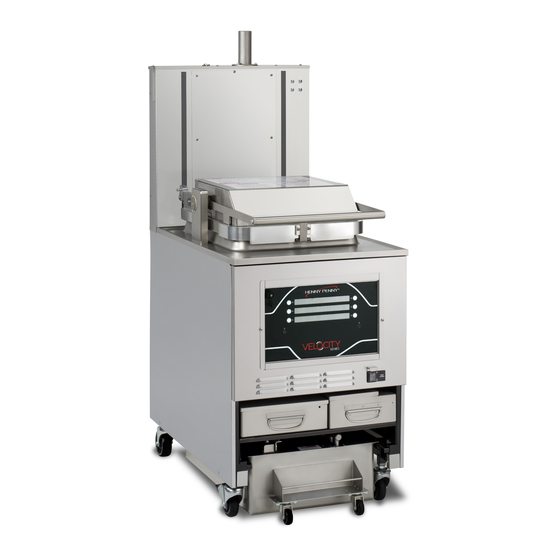
Velocity series pressure fryer
Hide thumbs
Also See for PXE-100:
- Operation manual (113 pages) ,
- Kit instructions (21 pages) ,
- Service manual (168 pages)
Table of Contents
Advertisement
OPERATOR'S
M A N U A L
VELOCITY SERIES
MODEL
PXE-100
Original Instructions
PRESSURE FRYER
TM
R E G I S T E R W A R R A N T Y O N L I N E AT W W W. H E N N Y P E N N Y. C O M
R E G I S T E R W A R R A N T Y O N L I N E AT W W W. H E N N Y P E N N Y. C O M
Read instructions before operating the appliance
Advertisement
Table of Contents
Troubleshooting

Related Manuals for Henny Penny PXE-100


Summary of Contents for Henny Penny PXE-100
-
Page 1: Pressure Fryer
MODEL PXE-100 R E G I S T E R W A R R A N T Y O N L I N E AT W W W. H E N N Y P E N N Y. C O M R E G I S T E R W A R R A N T Y O N L I N E AT W W W. - Page 3 HENNY PENNY ELECTRIC PRESSURE FRYER SPECIFICATIONS Pot Capacity 8 head of chicken - 24 lbs. (10.8 kg) 76 lbs. oil (34 Kg.) Electrical 208 VAC, 3 Phase, 50/60 Hz, 17 KW, 47.2 Amps 240 VAC, 3 Phase, 50/60 Hz, 17 KW, 40.9 Amps 480 VAC, 3 Phase, 50/60 Hz, 17 KW, 20.5 Amps...
- Page 4 PXE-100 DIMENSIONS...
- Page 5 HENNY PENNY 8 HEAD ELECTRIC PRESSURE FRYER Fryer must be installed and used in such a way to prevent water from contacting the shortening. This appliance is not intended to be operated by means of an external timer or a separate remote control system.
-
Page 7: Table Of Contents
TABLE OF CONTENTS Section Page Section 1. INTRODUCTION ..................... 1 Safety ......................1 Proper Care ....................2 Assistance ...................... 2 Section 2. INSTALLATION ....................... 3 Introduction ....................3 Unpacking...................... 3 Selecting the Fryer Location ................. 7 Leveling the Fryer ..................7 Ventilation of Fryer.................. -
Page 9: Section 1: Introduction
SECTION 1: INTRODUCTION The instructions in this manual have been prepared to aid you in learning the proper procedures for your equipment. Where information is of SAFETY particular importance or is safety related, the words NOTICE, CAUTION, or WARNING are used. Their usage is described below. If a problem occurs during the first operation of a new unit, recheck the Installation Section of the Operator’s Manual. -
Page 10: Proper Care
Equipotential Ground Symbol Waste Electrical and Electronic Equipment (WEEE) Symbol Shock Hazard Symbols Hot Surface Symbols As in all Henny Penny equipment, the unit requires care and 1-2. maintenance. Requirements for maintenance and cleaning are PROPER CARE contained in this manual and must be a regular part of the opera- tion of the unit. -
Page 11: Installation
SECTION 2: UNPACKING / INSTALLATION This section provides the installation and unpacking instructions. 2-1. INTRODUCTION • Any shipping damage should be noted in the presence of the delivery agent and signed prior to his or her departure. • Installation of this unit should be performed only by a qualified service technician. - Page 12 2-2. UNPACKING (CONT.) Do not drop counterweights , or personal injury could result. Each counterweight weighs approximately 20 lbs. (9 kg.) each. Remove the counterweights from the pallet, which are strapped to the pallet, under the fryer. Remove rear service cover. Load the six weights into the counterweight assembly.
- Page 13 Ramp Unloading 1. Front casters are fixed in the forward position. 2. Pry off the rail on either side of the pallet. 3. Prop up a ramp for each caster on the selected side. If ramp is not being used, rest the selected side’s casters onto the ground and move to step 4. 4.
- Page 14 REMOVE 2 BOLTS MARKED “A” TO RELEASE FRAME AFTER INSTALLING WEIGHT SEGMENTS INSERT 5TH & 6TH SEGMENT INSERT 3RD & 4TH SEGMENT INSERT 1ST & 2ND SEGMENT TO AVOID PERSONAL INJURY, - EACH WEIGHT SEGMENT WEIGHS ALL SEGMENTS MUST BE APPROXIMATELY 18 LBS.
-
Page 15: Selecting The Fryer Location
The proper location of the fryer is very important for operation, speed, 2-3. and convenience. Choose a location which provides easy loading and SELECTING THE unloading without interfering with the final assembly of food orders. LOCATION Operators find that frying from raw to finish, and holding the product in a warmer provides fast continuous service. -
Page 16: Ventilation Of Fryer
The fryer should be located with provision for venting into adequate exhaust 2-5. hood or ventilation system to permit efficient removal of steam exhaust and VENTILATION OF frying odors. The exhaust canopy must be designed to avoid interference FRYER with the operation of the fryer. Consult a local ventilation or heating company to help in designing an adequate system. -
Page 17: International Electrical Requirements
Units being used outside the United States may not be shipped with the 2-7. power cord attached to the unit because of the different wiring codes. INTERNATIONAL The fryers are available from the factory wired for 200, 240, 380 and ELECTRICAL 415 volts, 3 phase, 50 Hertz service. - Page 18 BE CERTAIN THE OIL IS NEVER ABOVE THE UPPER FRYPOT “FILL” LINE. • BE CERTAIN THAT THE GAS CONTROL VALVE AND BURNERS ARE PROPERLY ADJUSTED. (GAS UNITS ONLY) • USE RECOMMENDED PRODUCT LOAD SIZE (MAXIMUM 24 LB). FOR ASSISTANCE CALL THE HENNY PENNY SERVICE DEPARTMENT AT 1-800-417-8405. 1-937-456-8405 Dec. 2013...
-
Page 19: Section 3: Operation
SECTION 3: OPERATION 3-1. OPERATING COMPONENTS Item Description Function Steam-Stack Houses the dead-weight. Releases steam when pressurized Fresh Oil Tank Tops the pot off with fresh oil when low Power Switch Turns power to the unit ON/ OFF Condensation Pan Reservoir that hold excess condensation that drains from the pot Oil Drain Pan Oil is drained into this pan and then is pumped through filters to help... -
Page 20: Control Overview
This section gives a control board overview and explains all the 3-2. buttons, displays and features. CONTROL OVERVIEW Figure 3-1 Figure 3-2 Figure 3-3 Figure 3-4 March 2014... - Page 21 3-2. CONTROL OVERVIEW (CONT.) Item Fig. Description Function When the light is illuminated next to the button, this indicates this button Buttons has a product or action that can be reached by pressing. Pressing and holding this button will access the “MAIN” menu which Menu Button includes features such as filter, info mode, and programming.
-
Page 22: Display Options
This section describes the three (3) cook display options that this 3-3. unit is equipped with. The three options are as listed below: DISPLAY OPTIONS • 4+TITLE • 5+NEXT • 6 ITEMS To change the display option, see SPECIAL PROGRAM section. The 4+TITLE option shows up to four cook items along with the 3-4. -
Page 23: Next Option
The 5+NEXT option ashows up to five cook items, along with a 3-5. button that steps to the next cook menu. 5+NEXT OPTION All the cook options are displayed on the screen with the bot- tom-right reading “next>”. Pressing the button next to “next>” will access the next set of cook options. -
Page 24: Drain Pan Assembly
3-7. DRAIN PAN ASSEMBLY 1. Slide a filter envelope onto the filter screen so the plug is protrud- ing through the hole. During assembly, be sure to apply oil to all O-rings to lubricate to help prevent tears and loss. 2. -
Page 25: Product Racking Recommendations
3-8. The bottom position is to be avoided on small loads because PRODUCT RACKING it is closer to the cold zone. (The oil is cooler at the bottom RECOMMENDATIONS of the frypot and hotter at the top.) With bigger loads, however, there is generally enough turbulence in the oil that the bottom rack gets sufficient heat. -
Page 26: Lid Operation
3-9. LID OPERATION • LID MUST BE FULLY LATCHED PRIOR TO STARTING COOK CYCLE OR PRESSURIZED OIL AND STEAM MAY ESCAPE FRYPOT. SEVERE BURNS WILL RESULT. • TO AVOID SERIOUS PERSONAL INJURY, DO NOT OPERATE WITHOUT LID COVER IN PLACE AND ALL COMPONENTS INSTALLED. •... - Page 27 3-9. LID OPERATION (CONT.) DO NOT LIFT HANDLE OR FORCE LID LATCH OPEN BEFORE THE CONTROL ALARM SOUNDS, AND IS BLINKING “DONE” IN DISPLAY. To open lid: Gently raise handle until it stops. Push handle back until it stops. Lower the handle before attempting to raise the lid, or damage to the lid could result.
-
Page 28: Start-Up
If the oil is below 180 F (82 C), with the Main Power switch in 3-10. the ON position, the display will flash “START UP” “AUTO- MELT”. The oil heats slowly to prevent scorching of the oil. START-UP The heat cycles on and off to slowly heat the oil. When the oil temperature reaches 215°F (102°C), Auto-Melt mode terminates and the fryer begins heating up to the Auto-Mix temperature of 360°F (182°C). -
Page 29: Filling The Oil Tank
The fresh oil tank automatically tops off the oil in the frypot 3-11. when it senses the oil level is low. User should add fresh oil to FILLING THE OIL the tank as needed. DO NOT add fresh oil directly to the frypot. TANK Pull the fresh oil tank out of the front of the fryer. -
Page 30: Filter Pump Motor Protector-Manual Reset
To prevent burns caused by splashing oil, turn the unit’s main power switch to the OFF position before resetting the filter pump motor’s manual reset protection device. As in all food service equipment, the Henny Penny pressure 3-14. fryer does require care and proper maintenance. The table below REGULAR provides a summary of scheduled maintenance. -
Page 31: Initial Oil Fill
3-15. INITIAL OIL FILL The oil level must always be above the heating elements when the fryer is heating and at the frypot level indicators on the rear of the frypot (Figure 3-3). Failure to follow these instructions could result in a fire and/or damage to the fryer. -
Page 32: Basic Operation
Follow the procedure below on the initial start-up of the fryer, 3-16. and each time the fryer is brought from a cold, or shut down BASIC OPERATION condition, back into operation. These are basic, general instructions. DO NOT OVERLOAD, OR PLACE PRODUCT WITH EXTREME MOISTURE CONTENT INTO THE RACKS. -
Page 33: Care Of The Oil
At the end of the cycle, pressure begins venting 3-16. automatically, alarm sounds, and the display shows “DONE”. At this time, press the “DONE” button. BASIC OPERATION (CONT.) Unlock and raise the lid cautiously. Use the rack handles, remove the racks of product from the carrier, starting with the top rack. -
Page 34: Filtering Instructions
EXCESSIVE SMOKING OR FOAMING. SERIOUS BURNS, PERSONAL INJURY, FIRE, AND/OR PROPERTY DAMAGE COULD RESULT. The Henny Penny electric 8 head fryer the fryer automatically performs a polish during morning startup, automatically filters after every cook cycle, and requires a single “Daily” maintenance filter each day;... - Page 35 3-19. Quick Filter FILTERING Option 1 allows you to perform a quick filter of the oil. After every INSTRUCTIONS cook cycle, the fryer will automatically run a quick filter. You can choose to do one at any time by selecting this option. (CONT.) Once you have pressed 1 for “QUICK FILTER”, a “CONFIRM”...
- Page 36 Daily Filter 3-19. Option 2 allows you to perform a daily filter of the oil. This filter FILTERING cycle will drain the pot completely enabling the user to clean the pot. INSTRUCTIONS (CONT.) Once you have pressed 2 for “DAILY FILTER”, a “CONFIRM” prompt will appear on display.
- Page 37 3-19. FILTERING INSTRUCTIONS Polish Option 3 allows you to polish oil. (CONT.) Once you have pressed 3 for “POLISH”, a “CONFIRM” prompt will appear on display. You can cancel by pressing the button next to the X or confirm by pressing the button next to the √. Once you have confirmed YES, the drain will open automatically and the oil will start to drain.
-
Page 38: Bulk Dispose
Option 7 will access “DISPOSE”. The bulk dispose option al- lows the oil to be discarded to an external discard tank from the 3-20. drain pan. BULK DISPOSE Confirm controls are set to the particular set up in the location. See Special Programming for further detail on set up. -
Page 39: Changing The Filter Envelope
The filter envelope should be changed daily, or whenever it becomes 3-21. clogged with crumbs. CHANGING THE FILTER ENVELOPE Refer back to the Drain Pan Assembly section for instructions. Use protective cloth or glove when disconnecting the filter union or severe burns could result. If the filter pan is moved while full of oil, use care to prevent splashing, or severe burns could result. - Page 40 After the initial installation of the fryer, as well as before every change of oil, the frypot should be thoroughly cleaned as follows: 3-22. CLEAN-OUT MODE Be sure the oil is disposed properly. If the unit has bulk oil, see Bulk Dispose (Section 3-20) for instructions. (CONT.) Turn the POWER switch to OFF position.
- Page 41 With the fryer off, the display will read, “-OFF-” “(soaking)” with “done√” in the bottom right-hand display. 3-22. Use a scrub brush to periodically scrub the vat walls to loosen CLEAN-OUT MODE any crumbs or debris. (CONT.) Once the desired time, according to the uses discretion, has expired, press the button next to “done√”.
- Page 42 Clean-Out: Draining the Water The display with read “IS CART OR PAN IN PLACE?”. A 3-22. bucket, tub or the drain pan needs to be in place under the drain CLEAN-OUT MODE before proceeding to draining. (CONT.) If using the drain pan, remove all the internal parts so the pan is empty.
- Page 43 Repeat the following steps as needed to ensure all the cleaner is out of the pot. 3-22. CLEAN-OUT MODE Once the pot is rinsed clean of all chemical water, press the (CONT.) button next to “next►”. Purge Oil Lines This step is to clear the oil lines of any remaining water that may be left over from cleaning or rinsing.
-
Page 44: Preventive Maintenance
MAINTENANCE Cleaning slides (Nylatrons) - Monthly Spray Henny Penny biodegradable, food safe, foaming degreaser (part no. 12226) on Nylatrons. Raise lid up and down several times to spread the degreaser. Wipe Nylatrons to remove food soil, grease, and degreaser residue. - Page 45 3-23. Cleaning DeadWeight-Monthly PREVENTIVE MAINTENANCE (CONT.) DO NOT REMOVE DEADWEIGHT ASSEMBLY WHILE FRYER IS OPERATING OR SEVERE BURNS OR OTHER INJURIES WILL RESULT. Allow the steam stack enough time to cool before proceeding with the following steps. Loosen the 3 thumb screws that secure the steam stack to the top of the fryer.
- Page 46 Inspect Counter-weight Cables-Annually PREVENTIVE MAINTENANCE Henny Penny 8 head fryers use two cables in the counter-weight (CONT.) mechanism that helps in the raising and lowering of the lid. Cables should be visually inspected yearly, either as part of a planned maintenance program or during a routine service call.
-
Page 47: Section 4. Programming
SECTION 4: PROGRAMMING This section shows how to access the programming 4-1. (“PROG”) menu that access the products, cook and special PROGRAM MENU program. 1. PRODUCTS 6. FILTER CONTROL 1.PRODUCTS 7.TECH MODE 2. COOK MENUS 7. TECH MODE 8. STATS MODE 2.COOK MENUS 8.STATS MODE 3. - Page 48 9. Press the button next to the √ to confirm complete. 4-2. PRODUCT 10. Press the right-arrow button to advance to “LINK ID”. The PROGRAMMING Link ID is what is displayed in the cook menu. This is used as (CONT.) an abbreviation or short name.
-
Page 49: Special Programming
This section shows how to access the Special Program area of 4-3. the controls in order to program cook menus, clock, and other SPECIAL features. PROGRAMMING Push and hold until the display reads *MAIN*. Enter the code: 1, 2, 3 Press the again to access the next set of options. - Page 50 SP-6 • AUDIO TONE (Frequency) 4-3. SPECIAL Press the + or - to adjust the frequency setting, PROGRAMMING (CONT.) Press the button next to “test” on the display. SP-7 • MELT CYCLE Specify the desired Melt Mode heating cycle. Use the + or - to select wither “Solid” or “Liquid”. SP-8 •...
- Page 51 4-3. SP-18 • BULK OIL SUPPLY? SPECIAL PROGRAMMING Use the + or - buttons to select either “YES” or “NO” for (CONT.) whether or not a bulk oil supply is available for refilling the ATO oil tank and vat with fresh oil. SP-22 •...
-
Page 52: Section 5. Trouble Shooting
Filter Control Mode allows the parameters during a filter cycle to 4-4. be modified for the best results depending on the oil type being FILTER CONTROL used. Each parameter are grouped into sections that control a particular settings. The section are grouped as follows. See the next page for the full list of Filter Control programs. - Page 53 Quick Filter Settings FC-1 “QUICK FILTER: AFTER ‘X’ COOKS” 4-4. FC-2 “QUICK FILTER: DROP OIL: TIME” FILTER CONTROL FC-3 “QUICK FILTER: DROP OIL: DRAIN OPENING” (CONT.) FC-4 “QUICK FILTER: FILTER: TIME” FC-5 “QUICK FILTER: FILTER: DRAIN OPENING” FC-6 “QUICK FILTER: FILL: DETECT AT LEVEL PROBE, KEEP PUMPING” FC-7 “QUICK FILTER: NORMAL FILL TIME”...
- Page 54 Quick Filter Settings 4-4. FILTER CONTROL These parameters control the Quick Filter operation, which (CONT.) activates automatically after a cook cycle, and may also be initiated manually from the Filter Menu. The Quick Filter has three basic steps: DROP: Opens the drain and drops the oil level by a certain amount.
- Page 55 4-4. FC-2 “QUICK FILTER: DROP OIL: TIME” FILTER CONTROL FC-3 “QUICK FILTER: DROP OIL: DRAIN (CONT.) OPENING” For the “Drop” phase: how long to spend dropping the oil level, and how far to open the drain valve during this step. Enter a new value by using the product numbers.
- Page 56 FC-7 QUICK FILTER: FILL--NO DETECT: MAX 4-4. PUMP FILTER CONTROL The expected time it takes to refill the vat at the end of a Quick (CONT.) Filter. Enter a new value by using the product numbers. Press the button next to √ to accept the new value. Press the button next to X to return to default or previous setting.
- Page 57 FC-10 “DAILY FILTER + POLISH: FILL: DETECT 4-4. AT LEVEL PROBE, KEEP PUMPING” FILTER CONTROL When refilling the pot, specifies how long to keep pumping after (CONT.) the oil reaches the upper probe and the expected temperature rise is observed. Enter a new value by using the product numbers.
- Page 58 Polish Settings 4-4. FC-12 “POLISH: DROP OIL: TIME” FILTER CONTROL FC-13 “POLISH: DROP OIL: DRAIN OPENING” (CONT.) For the “Drop” phase: how long to spend dropping the oil level, and how far to open the drain valve during this step. Enter a new value by using the product numbers.
- Page 59 FC-17 “POLISH: FILL: NO DETECT: MAX PUMP” 4-4. If the fryer pumps for this amount of time during the Fill phase FILTER CONTROL without observing a temperature rise on the upper temperature probe, the control turns the pump off, and asks “IS POT (CONT.) FILLED?”.
- Page 60 FC-20 “AUTO-TOPOFF: REPEAT” 4-4. Specifies how long the control waits before assessing the oil FILTER CONTROL level and generating a second ATO pulse if the oil level is still (CONT.) low. Enter a new value by using the product numbers. Press the button next to √...
- Page 61 Start-Up Mode Settings 4-4. FC-23 “START-UP: NEEDED IF TEMP < X” FILTER CONTROL If the oil temperature is below 215°F when the fryer is turned on, the fryer always executes a Melt Mode -- regardless of this (CONT.) “Start-up Needed” setting. Melt Mode is important in assuring gentle heating of the oil when it is thick and perhaps not yet flowing well.
- Page 62 FC-26 “START-UP MIX: DROP OIL: TIME” 4-4. This setting specifies how long the oil should drain during the FILTER CONTROL “Drop” phase of the Start-up Mix. (CONT.) Enter a new value by using the product numbers. Press the button next to √ to accept the new value. Press the button next to X to return to default or previous setting.
- Page 63 FC-30 “START-UP ATO CHECK: ENABLED?” 4-4. Specifies whether or not the ATO (auto-topoff) Check -- the third FILTER CONTROL step of the Start-up Mode -- is enabled. (CONT.) Press the + or - to select either “YES” or “NO”. FC-31 “START-UP ATO CHECK: PRE-HEAT MAX TEMP”...
- Page 64 Cook Mode Auto Mix Settings 4-4. FILTER CONTROL FC-34 “COOK MODE AUTO-MIX: ENABLED?” (CONT.) This setting determines whether or not the Cook Mode Auto-Mix feature is enabled. Press the + or - to select either “YES” or “NO”. FC-35 “COOK MODE AUTO-MIX: DROP OIL: TIME”...
- Page 65 FC-38 “COOK MODE AUTO-MIX: FILL: NO 4-4. DETECT: MAX PUMP” FILTER CONTROL If the fryer pumps for this amount of time during the Fill phase (CONT.) without observing a temperature rise on the upper temperature probe, the control turns the pump off, and asks “IS POT FILLED?”.
- Page 66 FC-42 “COOK MODE TIMED AUTO-MIX, IF BAD 4-4. BOTTOM PROBE” FILTER CONTROL This option is used only if the temperature probe on the bottom (CONT.) of the pot has failed or is disconnected. Enter a new value by using the product numbers. Press the button next to √...
-
Page 67: Troubleshooting Guide
SECTION 5: TROUBLESHOOTING 5-1. TROUBLESHOOTING GUIDE PROBLEM CAUSE CORRECTION Power switch on but fryer • Open circuit • Fryer plugged in completely inoperative • Check breaker or fuse at wall Pressure not exhausting at • Solenoid or exhaust line clogged •... -
Page 68: Error Codes
In the event of a control system failure, the digital display will show an “Error 5-2. Message”. These messages are coded: “E04”, “E05”, “E06”, “E41”. A constant ERROR CODES tone is heard when an error code is displayed, and to silence this tone, press any of the product buttons. - Page 69 DISPLAY CAUSE CORRECTION Check the error log to find out the fry pot temperature at the time the high limit tripped. If this was several degrees above the oil set “E-10A” High limit tripped while vat point temperature, test for a sticking contactor “HIGH LIMIT main probe temperature was at and replace if faulty.
- Page 70 DISPLAY CAUSE CORRECTION Check the error log to find out the fry pot temperature at the time the high limit tripped. If this was several degrees above the oil set High limit tripped while “E-10F” point temperature, test for a sticking contactor filtering (including AutoFilter, “HIGH LIMIT and replace if faulty.
- Page 71 DISPLAY CAUSE CORRECTION • Check deadweight chamber for any “E-14” Pressure is too high within the obstruction “PRESSURE TOO frypot • Check the steam exhaust passage for HIGH” obstruction Check the drain valve for obstruction. Carefully remove any obstruction found. If no obstruction, check to make sure both The control energized the drain connections to the drain valve are plugged in...
- Page 72 DISPLAY CAUSE CORRECTION System data lost. Both the RAM “E-41S” copy and stored copy of the • Replace control board if occures “SYSTEM DATA settings have been lost. Settings repeatedly LOST’ are reset to default “E-46C” • Check to ensure chip is not ejected from “INTERNAL SD Issue with microSD chip slot...
- Page 73 DISPLAY CAUSE CORRECTION “E-70B” Short in wires/ loose connection • Check connection “PWR SWITCH OR WIRES Power switch may be faulty • Replace power switch FAILED” “E-70C” Loose connection on the 15 pin “DRN JUMPER Check connection connector MISSING” Should you require outside assistance, call your “E-84”...
-
Page 75: Appendix A. Annual Preventive Maintenance
APPENDIX A: ANNUAL PREVENTIVE MAINTENANCE This Appendix contains the annual preventive maintenace checklist. Sept. 2014... - Page 76 Henny Penny PXE-100 Annual Inspection Checklist INSPECTION # CLEAN REPLACE Assess Frypot and Frame (remove rear cover and both side panels) Inspect the fry pot for leaks or oil accumulation Ensure the fryer sits level. Inspect the casters and fryer frame...
- Page 77 26. * Remove lid cover and inspect lid components – Please read and follow PXE-100 Lid Inspection instructions for this step. Remove and inspect the lid gasket and check the tightness of lid liner screws as per the instructions for this step. Replace the gasket if it has not been replaced in the last 12 months, or if the gasket is hardened, brittle, damaged, or blackened.
- Page 78 Lid latch Plumbing elbows Drain switch Splice connectors Copyright © 2017 Henny Penny Corporation. All rights reserved. Henny Penny and the Henny Penny logo are registered trademarks of Henny Penny Corporation in the United States and other countries.
- Page 80 Henny Penny Corporation P.O.Box 60 Eaton,OH 45320 1-937-456-8400 1-937-456-8402 Fax Toll free in USA 1-800-417-8417 1-800-417-8434 Fax www.hennypenny.com *FM05-108-E Henny Penny Corp., Eaton, Ohio 45320, Revised 04-01-17...