HP ProLiant ML30 Gen9 Maintenance And Service Manual
Hide thumbs
Also See for ProLiant ML30 Gen9:
- User manual (112 pages) ,
- Maintenance and service manual (100 pages) ,
- User manual (110 pages)
Table of Contents
Advertisement
Quick Links
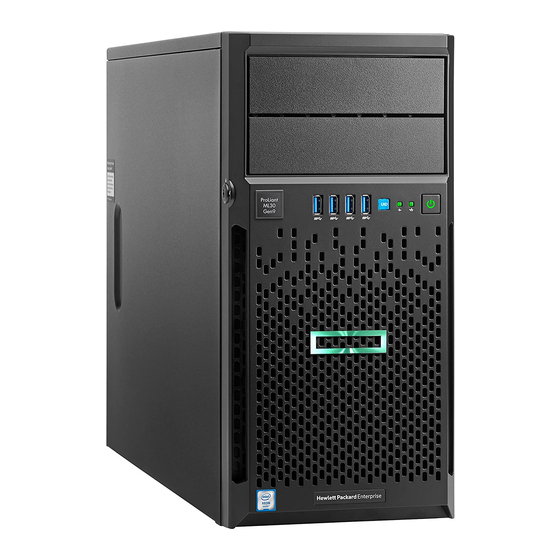
HPE ProLiant ML30 Gen9 Server
Maintenance and Service Guide
Abstract
This guide describes identification and maintenance procedures, diagnostic tools, specifications
and requirements for hardware components and software. This guide is for an experienced
service technician.
Part Number: 825545-003
Published: March 2017
Edition: 3
Advertisement
Table of Contents

Related Manuals for HP ProLiant ML30 Gen9


Summary of Contents for HP ProLiant ML30 Gen9
- Page 1 HPE ProLiant ML30 Gen9 Server Maintenance and Service Guide Abstract This guide describes identification and maintenance procedures, diagnostic tools, specifications and requirements for hardware components and software. This guide is for an experienced service technician. Part Number: 825545-003 Published: March 2017...
- Page 2 © 2015, 2017 Hewlett Packard Enterprise Development LP Notices The information contained herein is subject to change without notice. The only warranties for Hewlett Packard Enterprise products and services are set forth in the express warranty statements accompanying such products and services. Nothing herein should be construed as constituting an additional warranty. Hewlett Packard Enterprise shall not be liable for technical or editorial errors or omissions contained herein.
-
Page 3: Table Of Contents
Contents Customer self repair..................6 Illustrated parts catalog................15 Mechanical components........................15 System components.......................... 17 Removal and replacement procedures............27 Required tools........................... 27 Safety considerations........................27 Preventing electrostatic discharge..................27 Symbols on equipment......................27 Server warnings and cautions....................28 Preparation procedures for hardware replacement................28 Powering down the server ..................... - Page 4 Troubleshooting..................64 Troubleshooting resources........................ 64 Diagnostic tools..................65 HPE iLO.............................65 Product QuickSpecs....................... 65 Active Health System......................65 HPE ProLiant Pre-boot Health Summary................65 Integrated Management Log....................65 HPE Insight Remote Support....................66 HPE Insight Remote Support central connect............. 66 HPE Insight Online direct connect................66 Insight Online.......................
- Page 5 Storage cabling..........................87 Drive enablement option cabling.................... 87 Tape drive option cabling......................88 Four-bay LFF non-hot-plug drive cage cabling ..............89 Four-bay LFF hot-plug drive cage option cabling..............90 Eight-bay SFF hot-plug drive cage option cabling..............90 Specifications.................... 93 Environmental specifications......................93 Server specifications.........................
-
Page 6: Customer Self Repair
Customer self repair Hewlett Packard Enterprise products are designed with many Customer Self Repair (CSR) parts to minimize repair time and allow for greater flexibility in performing defective parts replacement. If during the diagnosis period Hewlett Packard Enterprise (or Hewlett Packard Enterprise service providers or service partners) identifies that the repair can be accomplished by the use of a CSR part, Hewlett Packard Enterprise will ship that part directly to you for replacement. - Page 7 REMARQUE: Certaines pièces Hewlett Packard Enterprise ne sont pas conçues pour permettre au client d'effectuer lui-même la réparation. Pour que la garantie puisse s'appliquer, Hewlett Packard Enterprise exige que le remplacement de la pièce soit effectué par un Mainteneur Agréé. Ces pièces sont identifiées par la mention "Non"...
- Page 8 Per ulteriori informazioni sul programma CSR di Hewlett Packard Enterprise, contattare il centro di assistenza di zona. Per il programma in Nord America fare riferimento al sito Web. Servizio di garanzia per i soli componenti La garanzia limitata Hewlett Packard Enterprise può includere un servizio di garanzia per i soli componenti. Nei termini di garanzia del servizio per i soli componenti, Hewlett Packard Enterprise fornirà...
- Page 9 Reparaciones del propio cliente Los productos de Hewlett Packard Enterprise incluyen muchos componentes que el propio usuario puede reemplazar (Customer Self Repair, CSR) para minimizar el tiempo de reparación y ofrecer una mayor flexibilidad a la hora de realizar sustituciones de componentes defectuosos. Si, durante la fase de diagnóstico, Hewlett Packard Enterprise (o los proveedores o socios de servicio de Hewlett Packard Enterprise) identifica que una reparación puede llevarse a cabo mediante el uso de un componente CSR, Hewlett Packard Enterprise le enviará...
- Page 10 • Verplicht—Onderdelen waarvoor reparatie door de klant verplicht is. Als u Hewlett Packard Enterprise verzoekt deze onderdelen voor u te vervangen, worden u voor deze service reiskosten en arbeidsloon in rekening gebracht. • Optioneel—Onderdelen waarvoor reparatie door de klant optioneel is. Ook deze onderdelen zijn ontworpen voor reparatie door de klant.
- Page 11 Conforme a disponibilidade e o local geográfico, as peças CSR serão enviadas no primeiro dia útil após o pedido. Onde as condições geográficas permitirem, a entrega no mesmo dia ou em quatro horas pode ser feita mediante uma taxa adicional. Se precisar de auxílio, entre em contato com o Centro de suporte técnico da Hewlett Packard Enterprise para que um técnico o ajude por telefone.
- Page 12 Customer self repair...
- Page 13 Customer self repair...
- Page 14 Customer self repair...
-
Page 15: Illustrated Parts Catalog
Illustrated parts catalog Mechanical components Hewlett Packard Enterprise continually improves and changes product parts. For complete and current supported parts information, see the Hewlett Packard Enterprise PartSurfer website. Item Description Spare part number Customer self repair Air baffle 825097-001 Mandatory Tower bezel assembly 825096-001 Mandatory... - Page 16 Optional—Parts for which customer self repair is optional. These parts are also designed for customer self repair. If, however, you require that Hewlett Packard Enterprise replace them for you, there may or may not be additional charges, depending on the type of warranty service designated for your product. No—Some Hewlett Packard Enterprise parts are not designed for customer self repair.
-
Page 17: System Components
Verplicht—Onderdelen die de klant zelf moet vervangen. Als u Hewlett Packard Enterprise vraagt deze onderdelen te vervangen, worden er reis- en arbeidskosten voor deze service in rekening gebracht. Optioneel—Onderdelen die de klant zelf kan vervangen. Deze onderdelen zijn ook ontworpen om door de klant zelf te worden vervangen. - Page 18 Item Description Spare part Customer self number repair HPE 460W CS Gold hot-plug power supply 511777-001 Mandatory HPE Redundant power supply cage 686665-001 Optional HPE Redundant power supply backplane 686744-001 Optional HPE 350W E1.0 Power Supply 821243-001 Optional HPE 350W E2.0 Power Supply* 821244-001 Optional Front I/O assembly...
- Page 19 Item Description Spare part Customer self number repair c) 3.50-GHz Intel Xeon E3-1240 v5, 4C, 8MB, 80W* 829990-001 Optional d) 2.10-GHz Intel Xeon E3-1240L v5, 4C, 8MB, 25W* 829989-001 Optional e) 3.60-GHz Intel Xeon E3-1270 v5, 4C, 8MB, 80W* 829992-001 Optional f) 3.30-GHz Intel Pentium G4400, 2C, 3MB, 54W* 841855-001...
- Page 20 Item Description Spare part Customer self number repair d) H241 host bus adapter* 750054-001 Optional Graphics options — — a) NVIDIA Quadro K2200 GPU module* 765148-002 Optional b) NVIDIA Quadro M2000 GPU module* 855180-001 Optional Optical drives — — a) 9.5mm SATA DVD-ROM* 652296-001 Optional b) 9.5mm SATA DVD-RW*...
- Page 21 Item Description Spare part Customer self number repair h) 2TB 6G SATA 7.2k 3.5in SC MDL HDD* 658102-001 Mandatory i) 1TB 6G SATA 7.2k 3.5in SC MDL HDD* 657739-001 Mandatory j) HPE 1TB 6G SATA 7.2k 3.5in SC MDL HDD* 862128-001 Mandatory k) 3TB 6G SATA 7.2k 3.5in SC MDL HDD*...
- Page 22 Item Description Spare part Customer self number repair l) 4TB 6G SAS 7.2k 3.5in DP MDL SC HDD* 695842-001 Mandatory m) 6TB 12G SAS 7.2K 3.5 MDL SC DS HDD* 846610-001 Mandatory n) 10TB 12G SAS 7.2K LFF 512e MDL SC DS HDD* 857965-001 Mandatory o) 8TB 12G SAS 7.2K LFF 512e MDL SC DS HDD*...
- Page 23 Item Description Spare part Customer self number repair y) 960GB 6G SATA MU-3 SFF SC DS SSD* 872520-001 Mandatory z) 1.92TB 6G SATA MU-3 SFF SC DS SSD* 872522-001 Mandatory Hot-plug SFF SAS hard drives — — a) 600GB 12G SAS 10K 2.5in SC ENT HDD* 781577-001 Mandatory b) 1.2TB 12G SAS 10K 2.5in SC ENT HDD*...
- Page 24 Item Description Spare part Customer self number repair SSD M.2 Modules — — a) PCI riser with one 120 GB SSD M.2 module and SATA 797907-001 Mandatory cable* b) PCI riser with two 120 GB SSD M.2 module and SATA 797908-001 Mandatory cables*...
- Page 25 di un tecnico autorizzato per la sostituzione della parte. Queste parti sono contrassegnate con"No"nel catalogo parti illustrato. Zwingend—Teile, für die das Customer Self Repair-Verfahren zwingend vorgegeben ist. Wenn Sie den Austausch dieser Teile von Hewlett Packard Enterprisevornehmen lassen, werden Ihnen die Anfahrt- und Arbeitskosten für diesen Service berechnet.
- Page 26 Illustrated parts catalog...
-
Page 27: Removal And Replacement Procedures
Removal and replacement procedures Required tools You will need the following items for some procedures: • T-10/T-15 Torx screw driver • Flathead screwdriver • HPE Insight Diagnostics Safety considerations Before performing service procedures, review all the safety information. Preventing electrostatic discharge To prevent damaging the system, be aware of the precautions you must follow when setting up the system or handling parts. -
Page 28: Server Warnings And Cautions
This symbol indicates the presence of a hot surface or hot component. If this surface is contacted, the potential for injury exists. WARNING: To reduce the risk of injury from a hot component, allow the surface to cool before touching. This symbol indicates that the component exceeds the recommended weight for one individual to handle safely. -
Page 29: Removing The Bezel
To power down the server, use one of the following methods: • Press and release the Power On/Standby button. This method initiates a controlled shutdown of applications and the OS before the server enters standby mode. • Press and hold the Power On/Standby button for more than 4 seconds to force the server to enter standby mode. -
Page 30: Removing The Air Baffle
CAUTION: For proper cooling, do not operate the server without the access panel, baffles, and expansion slot covers, or blanks installed. If the server supports hot-plug components, minimize the amount of time the access panel is open. Procedure 1. Power down the server. 2. -
Page 31: Preparation Procedures For Server Operation
Preparation procedures for server operation Use the procedures in this section after removing or replacing any components before operating the server. Installing the air baffle Procedure Power down the server. Disconnect the power cord from the power source and the server. Remove the bezel. -
Page 32: Installing The Access Panel
10. Return the server to an upright position. 11. Connect the power cord to the power source and the server. 12. Power up the server. Installing the access panel Procedure 1. Power down the server. 2. Disconnect the power cord from the power source and the server. 3. -
Page 33: Powering Up The Server
Powering up the server Procedure 1. Connect each power cord to the server. 2. Connect each power cord to the power source. 3. Press the Power On/Standby button. The server exits standby mode and applies full power to the system. The system power LED changes from amber to green. -
Page 34: Replacing A Hot-Plug Drive
To replace the LFF drive blank, slide the component into the bay until it clicks into place. • Hot-plug SFF drive blank To replace the SFF drive blank, while pressing the release latch, slide the component into the bay until it is fully seated.. -
Page 35: Replacing A Four-Bay Lff Hot-Plug Drive Backplane Assembly
To replace the component, reverse the removal procedure. Replacing a four-bay LFF hot-plug drive backplane assembly WARNING: To reduce the risk of personal injury from hot surfaces, allow the drives and internal system components to cool before touching them. CAUTION: To prevent improper cooling and thermal damage, do not operate the server unless all bays are populated with either a component or a blank. -
Page 36: Replacing An Eight-Bay Sff Hot-Plug Drive Backplane Assembly
10. Remove the drive backplane. To replace the component, reverse the removal procedure. Replacing an eight-bay SFF hot-plug drive backplane assembly WARNING: To reduce the risk of personal injury from hot surfaces, allow the drives and internal system components to cool before touching them. CAUTION: To prevent improper cooling and thermal damage, do not operate the server unless all bays are populated with either a component or a blank. -
Page 37: Replacing A Drive In The Non-Hot-Plug Drive Cage
Remove the bezel. Place the server on its side with the access panel facing up. Remove all drives. Remove the access panel. Remove the air baffle. Disconnect all cables connected to any installed drives. Remove the drive cage. 10. Remove the drive backplane. To replace the component, reverse the removal procedure. - Page 38 CAUTION: To prevent improper cooling and thermal damage, do not operate the server unless all bays are populated with either a component or a blank. Procedure 1. Power down the server. 2. Disconnect the power cord from the power source and the server. 3.
-
Page 39: Replacing A Drive In The Drive Enablement Option
Replacing a drive in the drive enablement option WARNING: To reduce the risk of personal injury from hot surfaces, allow the drives and internal system components to cool before touching them. CAUTION: To prevent improper cooling and thermal damage, do not operate the server unless all bays are populated with either a component or a blank. -
Page 40: Replacing An M.2 Ssd Enablement Board
9. Remove the drive from the drive carrier. To replace the component, reverse the removal procedure. Replacing an M.2 SSD enablement board WARNING: To reduce the risk of personal injury from hot surfaces, allow the drives and internal system components to cool before touching them. -
Page 41: Replacing An M.2 Ssd Module
Procedure 1. Power down the server. 2. Disconnect the power cord from the power source and the server. 3. Remove the bezel. 4. Place the server on its side with the access panel facing up. 5. Remove the access panel. 6. -
Page 42: Replacing A Media Bay Blank
WARNING: To reduce the risk of personal injury from hot surfaces, allow the drives and internal system components to cool before touching them. CAUTION: To prevent improper cooling and thermal damage, do not operate the server unless all bays are populated with either a component or a blank. -
Page 43: Replacing A Dimm
To replace the component, reverse the removal procedure. Replacing a DIMM WARNING: To reduce the risk of personal injury from hot surfaces, allow the drives and internal system components to cool before touching them. CAUTION: To prevent improper cooling and thermal damage, do not operate the server unless all bays are populated with either a component or a blank. -
Page 44: Replacing A Front I/O Assembly
To replace the component, reverse the removal procedure. Replacing a front I/O assembly CAUTION: To prevent damage to electrical components, take the appropriate anti-static precautions before beginning any installation, removal or replacement procedure. Improper grounding can cause electrostatic discharge. Procedure 1. -
Page 45: Replacing A Front Pci Fan
8. Remove the front I/O module. To replace the component, reverse the removal procedure. Replacing a front PCI fan WARNING: To reduce the risk of personal injury from hot surfaces, allow the drives and internal system components to cool before touching them. CAUTION: To prevent improper cooling and thermal damage, do not operate the server unless all bays are populated with either a component or a blank. -
Page 46: Replacing A System Fan
Procedure 1. Power down the server. 2. Disconnect the power cord from the power source and the server. 3. Remove the bezel. 4. Place the server on its side with the access panel facing up. 5. Remove the access panel. 6. -
Page 47: Replacing A Smart Storage Battery
7. Remove any existing expansion boards blocking access to the system fan connector. 8. Remove the system fan: a. Disconnect the fan power cable. b. Remove the screws from the rear panel. c. Remove the fan. To replace the component, reverse the removal procedure. Replacing a Smart Storage Battery WARNING: To reduce the risk of personal injury from hot surfaces, allow the drives and internal system components... -
Page 48: Replacing A Smart Storage Battery Holder
To replace the component, reverse the removal procedure. Replacing a Smart Storage Battery holder WARNING: To reduce the risk of personal injury from hot surfaces, allow the drives and internal system components to cool before touching them. CAUTION: To prevent improper cooling and thermal damage, do not operate the server unless all bays are populated with either a component or a blank. -
Page 49: Replacing An Expansion Board
9. Remove the Smart Storage Battery holders. To replace the component, reverse the removal procedure. Replacing an expansion board WARNING: To reduce the risk of personal injury from hot surfaces, allow the drives and internal system components to cool before touching them. Procedure 1. -
Page 50: Replacing A Heatsink
7. Disconnect all cables connected to the expansion board. 8. Remove the PCIe slot cover retainer 9. Remove the expansion board. To replace the component, reverse the removal procedure. Replacing a heatsink WARNING: To reduce the risk of personal injury from hot surfaces, allow the drives and internal system components to cool before touching them. - Page 51 Replace the component: a. Clean the old thermal grease from the processor with the alchohol swab. Allow the alchohol to evaporate before continuing. b. Remove the thermal interface protective cover from the heatsink. CAUTION: Do not overtighten the screws as this might damage the board, connectors, or screws and voids the warranty of the system board.
-
Page 52: Replacing A Processor
10. Install the air baffle. 11. Install the access panel. 12. Return the server to an upright position. 13. Close and lock the tower bezel. 14. Connect the power cord to the power source and server. 15. Power on the server. The server exists standby mode and applies full power to the system. - Page 53 Place the server on its side with the access panel facing up. Remove the access panel. Remove the air baffle. Remove the heatsink. Open the processor locking lever, then open the processor retaining bracket. Grasp the processor by the edges, then lift it out of the socket. CAUTION: Failure to completely open the processor locking lever prevents the processor from seating during installation.
- Page 54 CAUTION: Be sure to close the processor socket retaining bracket before closing the processor locking lever. The lever should close without resistance. Forcing the lever closed can damage the processor and socket. CAUTION: To avoid damage to th processor, do not touch the bottom of the processor, especially the contact area.
-
Page 55: Replacing A 350W E1.0/E2.0 Non-Redundant Power Supply
a. Position the heatsink using the guide pin on the processor backplate. b. Tighten one pair of diagonally opposite screws halfway, then tighten the other pair of screws. c. Finish the installation by completely tightening the screws in the same sequence. 15. -
Page 56: Replacing A Redundant Power Supply Assembly
To replace the component, reverse the removal procedure. Replacing a redundant power supply assembly WARNING: To reduce the risk of personal injury from hot surfaces, allow the drives and internal system components to cool before touching them. Procedure Power down the server. Disconnect the power cord from the power source and the server. - Page 57 10. Remove the redundant power supply backplane. 11. Remove the redundant power supply cage: a. Remove the four screws securing the cage. b. Press and hold the release tab on the inside panel of the chassis. c. Push the cage towards the front of the chassis, then remove the component. Removal and replacement procedures...
-
Page 58: Replacing A System Board
To replace the component, reverse the removal procedure. Replacing a system board WARNING: To reduce the risk of personal injury from hot surfaces, allow the drives and internal system components to cool before touching them. CAUTION: To avoid ESD damage, when removing electrostatic-sensitive components from the failed system board, place the components on a static-dissipating work surface or inside separate antistatic bags. - Page 59 a. Remove the system board screws. b. Lift the system board out of the chassis. 15. Install the new system board. 16. Install the processor. Use the notches on both sides of the processor to properly align it into the socket. CAUTION: Failure to completely open the processor locking lever prevents the processor from seating during installation.
- Page 60 CAUTION: Be sure to close the processor socket retaining bracket before closing the processor locking lever. The lever should close without resistance. Forcing the lever closed can damage the processor and socket. 17. Close the processor retaining bracket, then secure the processor locking lever. 18.
- Page 61 CAUTION: Do not overtighten the screws as this might damage the board, connectors, or screws and voids the warranty of the system board. Install the heatsink: a. Position the heatsink using the guide pin on the processor backplate. b. Tighten one pair of diagonally opposite screws halfway, then tighten the other pair of screws. c.
-
Page 62: Replacing The System Battery
The server will automatically reboot. Replacing the system battery WARNING: The server contains an internal lithium manganese dioxide, a vanadium pentoxide, or an alkaline battery that provides power to the real-time clock. If this battery is not properly handled, a risk of the fire and burns exists. -
Page 63: Trusted Platform Module
10. Install the air baffle. 11. Install the access panel. 12. Install the bezel. 13. Return the server to an upright position. 14. Connect the power cord to the power source and the server. 15. Power up the server. For more information about battery replacement or proper disposal, contact an authorized reseller or an authorized service provider. -
Page 64: Troubleshooting
Troubleshooting Troubleshooting resources The HPE ProLiant Gen9 Troubleshooting Guide, Volume I: Troubleshooting provides procedures for resolving common problems and comprehensive courses of action for fault isolation and identification, issue resolution, and software maintenance on ProLiant servers and server blades. To view the guide, select a language: •... -
Page 65: Diagnostic Tools
Diagnostic tools HPE iLO iLO is a remote server management processor embedded on the system boards of HPE ProLiant and Synergy servers. iLO enables the monitoring and controlling of servers from remote locations. HPE iLO management is a powerful tool that provides multiple ways to configure, update, monitor, and repair servers remotely. -
Page 66: Hpe Insight Remote Support
• From within operating system-specific IML viewers: ◦ For Windows: IML Viewer ◦ For Linux: IML Viewer Application • From within the iLO web interface • From within Insight Diagnostics HPE Insight Remote Support Hewlett Packard Enterprise strongly recommends that you register your device for remote support to enable enhanced delivery of your Hewlett Packard Enterprise warranty, HPE support services, or Hewlett Packard Enterprise contractual support agreement. -
Page 67: Using Uefi System Utilities
• Configuring system devices and installed options • Enabling and disabling system features • Displaying system information • Selecting the primary boot controller • Configuring memory options • Selecting a language • Launching other preboot environments such as the Embedded UEFI Shell and Intelligent Provisioning For more information, see the UEFI System Utilities user guide for your product on the Hewlett Packard Enterprise website. -
Page 68: Re-Entering The Server Serial Number And Product Id
For more information about the iLO RESTful API and the RESTful Interface Tool, see the Hewlett Packard Enterprise website. Re-entering the server serial number and product ID After you replace the system board, you must re-enter the server serial number and the product ID: Procedure 1. -
Page 69: Usb Support
• Supports online array capacity expansion, logical drive extension, assignment of online spares, and RAID or stripe size migration • Provides diagnostic and SmartSSD Wear Gauge functionality on the Diagnostics tab • For supported controllers, provides access to additional features. For more information about HPE SSA, see the Hewlett Packard Enterprise website. -
Page 70: Component Identification
Component identification Front panel components Item Description Media drive bays USB 3.0 connectors Drive cage bay Front panel LEDs and buttons Component identification... -
Page 71: Front Panel Power Fault Leds
Item Description Status UID button/LED Solid blue = Activated Flashing blue: • 1 flash per second = Remote management or firmware upgrade in progress • 4 flashes per second = iLO manual soft reboot sequence initiated • 8 flashes per second = iLO manual hard reboot sequence in progress Off = Deactivated Power On/Standby button and system power... -
Page 72: Rear Panel Components
Subsystem LED behavior Removable HPE Flexible Smart Array controller/ 6 flashes Smart SAS HBA controller System board PCIe slots 7 flashes Power backplane or storage backplane 8 flashes Power supply 9 flashes Rear panel components Item Description Power supply NIC connector 2 Kensington lock slot Nic connector 1/ Shared iLO connector PCIe slot 4, PCIe3 x16 (16,8,4,1), full-length*... -
Page 73: Rear Panel Leds And Buttons
Rear panel LEDs and buttons Item Description Status UID LED Solid blue = Activated Flashing blue: • 1 flash per second = Remote management or firmware upgrade in progress • 4 flashes per second = iLO manual soft reboot sequence initiated •... -
Page 74: System Board Components
System board components Item Description RPS connector Processor DIMM slots System battery Trusted platform module connector 24-power connector Mini-SAS connector SATA connector 5 (for M.2 SSD 1) SATA connector 6 (for M.2 SSD 2) Internal USB 2.0 connector(for tape drive) Internal USB 2.0 connector microSD card slot Front PCI fan connector... -
Page 75: Dimm Slot Locations
Item Description NMI header PCIe slot 1 PCIe3 x8 (4,1), half-length* System maintenance switch PCIe slot2 PCIe3 x4 (1) full-length* PCIe slot 3 PCIe3 x4 (1), full-length* PCIe slot 4 PCIe3 x16 (16,8,4,1), full-length* System fan connector 4-pin power connector * For more information on the expansion slot specifications, see "PCIe expansion slot definitions."... -
Page 76: System Maintenance Switch
System maintenance switch Position Default Function Off = iLO security is enabled. On = iLO security is disabled. Off = System configuration can be changed. On = System configuration is locked. Reserved Reserved Off = Power-on password is enabled. On = Power-on password is disabled. Off = No function On = ROM reads system configuration as invalid. -
Page 77: Drive Numbering
administrators is to restart the system. Resetting the system erases any information which could support problem analysis, but the NMI feature preserves that information by performing a memory dump before a system reset. To force the system to invoke the NMI handler and generate a crash dump log, do one of the following: •... -
Page 78: Hot-Plug Drive Definitions
Hot-plug drive definitions Item Status Definition Locate Solid blue The drive is being identified by a host application. Flashing blue The drive carrier firmware is being updated or requires an update. Activity ring Rotating green Drive activity. No drive activity. Do not remove Solid white Do not remove the drive. -
Page 79: Fan Locations
Item Status Definition Flashing amber/green The drive is a member of one or more logical drives and predicts the drive will fail. Flashing amber The drive is not configured and predicts the drive will fail. Solid amber The drive has failed. The drive is not configured by a RAID controller. -
Page 80: Cabling
Cabling Cabling overview This section provides guidelines to help make informed decisions about cabling the server and hardware options to optimize performance. For information on cabling peripheral components, see the white paper on high-density deployment at the Hewlett Packard Enterprise website. CAUTION: When routing cables, always be sure that the cables are not in a position where they can be pinched or crimped. -
Page 81: System Fan Cabling
System fan cabling Front PCI fan option cabling Slim optical disk drive option cabling • Slim optical disk drive to 350W non-redundant power supply System fan cabling... -
Page 82: Power Supply Cabling
Item Description Optical disk drive power cable SATA cable 4-pin power cable to 4-pin power supply extension cable • Slim optical disk drive to redundant power supply Item Description Optical disk drive power cable SATA cable 4-pin power cable to 4-pin power supply extension cable Power supply cabling Power supply cabling... -
Page 83: Hpe 350W (E-Star 1.0/2.0) Non-Hot-Plug Power Supply Cabling
HPE 350W (E-star 1.0/2.0) non-hot-plug power supply cabling • Four-bay LFF non-hot-plug drive configuration Item Description 8-pin drive power cable Non-hot-plug drive power cable 4-pin power cable 24-pin power cable • Four-bay LFF hot-plug drive configuration HPE 350W (E-star 1.0/2.0) non-hot-plug power supply cabling... -
Page 84: Redundant Power Supply Cabling
Item Description 8-pin drive power cable 4-pin power cable 24-pin power cable • Eight-bay SFF hot-plug drive configuration Item Description 8-pin drive power cable 4-pin power cable 24-pin power cable Redundant power supply cabling • Four-bay LFF non-hot-plug drive configuration Redundant power supply cabling... - Page 85 Item Description 24-pin power supply cable 4-pin power supply cable RPS sideband signal cable 10-pin to 8-pin power supply cable • Four-bay LFF hot-plug drive configuration Item Description 24-pin power supply cable 4-pin power supply cable RPS sideband signal cable 10-pin to 8-pin power supply cable •...
-
Page 86: Fbwc Option Cabling
Item Description 24-pin power supply cable 4-pin power supply cable RPS sideband signal cable 10-pin to 8-pin power supply cable FBWC option cabling Smart Storage Battery option cabling FBWC option cabling... -
Page 87: M.2 Ssd Option Cabling
M.2 SSD option cabling Item Description M.2 SSD 1 SATA cable M.2 SSD 2 SATA cable Storage cabling Drive enablement option cabling • Drive enablement option to 350W non-hot-plug power supply M.2 SSD option cabling... -
Page 88: Tape Drive Option Cabling
Item Description SATA cable Drive power cable • Drive enablement option to redundant power supply Item Description SATA cable Drive power cable Tape drive option cabling • Tape drive option to 350W non-redundant power supply Tape drive option cabling... -
Page 89: Four-Bay Lff Non-Hot-Plug Drive Cage Cabling
Item Description USB cable Drive power cable Power extension cable Power supply cable • Tape drive option to redundant power supply Item Description USB cable Drive power cable Power supply cable Four-bay LFF non-hot-plug drive cage cabling Four-bay LFF non-hot-plug drive cage cabling... -
Page 90: Four-Bay Lff Hot-Plug Drive Cage Option Cabling
Item Description Power cable 10-pin to 8-pin power extension cable Mini-SAS cable Four-bay LFF hot-plug drive cage option cabling Item Description Mini-SAS cable Power cable Eight-bay SFF hot-plug drive cage option cabling • Eight-bay SFF hot-plug drive cage cabling to system board (supports up to 4 drives) Four-bay LFF hot-plug drive cage option cabling... - Page 91 Item Description SATA cable Drive power cable • Eight-bay SFF hot-plug drive cage cabling to Smart Array controller (supports up to 8 drives) Item Description Mini-SAS Y-cable Power cable • Eight-bay SFF hot-plug drive cage cabling to Host Bust Adapter (supports up to 8 drives) Cabling...
- Page 92 Item Description Mini-SAS cable Power cable Mini-SAS cable Cabling...
-
Page 93: Specifications
Specifications Environmental specifications Specification Value Temperature range* Operating 10° C to 35° C (50° F to 95° F) Nonoperating -30° C to 60° C (-22° F to 140° F) Relative humidity (noncondensing) 10% to 90% Operating, maximum wet bulb temperature of 28°C (82.4°F) 5% to 95% Nonoperating, maximum wet bulb temperature of... -
Page 94: Hpe 350 W Power Supply (E-Star 1.0)
HPE 350 W Power Supply (E-star 1.0) Specification Value Input requirements — Rated input voltage 100 V AC to 240 V AC Rated input frequency 47 Hz to 63 Hz Rated input current 6 A to 3 A Rated input power 427 W at 115 V AC input 427 W at 240 V AC input Efficiency... -
Page 95: Hpe 460W Cs Gold Hot-Plug Power Supply
Specification Value Maximum peak power 350 W at 115 V AC input 350 W at 230 V AC input Rated output power 350 W HPE 460W CS Gold hot-plug power supply Specification Value Input requirements — Rated input voltage 100 V AC to 240 V AC Rated input frequency 50 Hz to 60 Hz Rated input current... -
Page 96: Support And Other Resources
Support and other resources Accessing Hewlett Packard Enterprise Support • For live assistance, go to the Contact Hewlett Packard Enterprise Worldwide website: http://www.hpe.com/assistance • To access documentation and support services, go to the Hewlett Packard Enterprise Support Center website: http://www.hpe.com/support/hpesc Information to collect •... -
Page 97: Remote Support
Some parts do not qualify for CSR. Your Hewlett Packard Enterprise authorized service provider will determine whether a repair can be accomplished by CSR. For more information about CSR, contact your local service provider or go to the CSR website: http://www.hpe.com/support/selfrepair Remote support Remote support is available with supported devices as part of your warranty or contractual support... -
Page 98: Acronyms And Abbreviations
Acronyms and abbreviations ABEND abnormal end Array Configuration Utility Advanced Memory Protection application program interface ASHRAE American Society of Heating, Refrigerating and Air-Conditioning Engineers Automatic Server Recovery American wire gauge column address strobe Canadian Standards Association Customer Self Repair DDR3 ouble data rate-3 DDR4 double data rate-4... - Page 99 International Electrotechnical Commission Integrated Lights-Out Integrated Management Log International Organization for Standardization JBOD just a bunch of disks JSON JavaScript Object Notation large form factor Lights-Out Management LRDIMM load reduced dual in-line memory module NAND Not AND nonmaskable interrupt NVDIMM non-volatile dual in-line memory module NVRAM nonvolatile memory...
- Page 100 RBSU ROM-Based Setup Utility RDIMM registered dual in-line memory module REST representational state transfer RoHS Restriction of Hazardous Substances serial attached SCSI SATA serial ATA Secure Digital SELV separated extra low voltage small form factor Service Pack for ProLiant solid-state device standard (DIMM voltage) TMRA recommended ambient operating temperature...
- Page 101 Version Control Agent VCRM Version Control Repository Manager Acronyms and abbreviations...