Advertisement
Quick Links
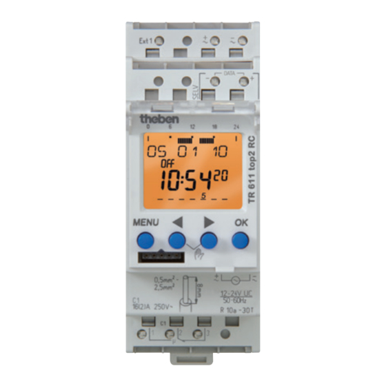
Time switch
EN
TR 611 top2 RC 24 V
6114300
1. Basic safety information
WARNING
Danger of death through electric shock or fire!
Installation should only be carried out by a
¾
¾
qualified electrician!
•
The device is designed for installation on DIN top hat
rails (in accordance with EN 60715)
•
The device corresponds to type 1 BSTU in accordance
with IEC/EN 60730-2-7
•
Power reserve (10 years) is reduced if memory card is
inserted (using battery power)
!
OBELISK top2 memory card: Avoid mechanical overload
and contamination during storage/transportation
2. Proper use
•
The time switch is used for lighting, ventilation and
flushing applications etc.
•
Only for use in closed, dry rooms
!
Do not use on safety devices, e.g. escape route doors, fire
safety equipment etc.
Disposal
Dispose of device in environmentally sound manner
†
¾
3. Installation and connection
Mounting the time switch
WARNING
Danger of death through electric shock or fire!
Installation should only be carried out by a
¾
¾
qualified electrician!
307096
click
Load line connection
Plug-in
screwless termi-
nal NC contact
Test tap
OBELISK top2
memory card
(9070404)
Mount on DIN top hat rails (as defined in EN 60715)
†
¾
Switched voltage-free
†
¾
Ensure device cannot be switched on
†
¾
Check absence of voltage
†
¾
Earth and bypass
†
¾
Cover or shield any adjacent live components
†
¾
L Best reception is achieved by installing the antenna on the
outside of the building
Connecting the cable
Wiring diagrams
+ ~ – ~
Ext1
RC
C1
1 2 3
L Ensure correct polarity.
L Lay separate cable for antenna power supply.
L Align the radio antenna so that the green LED flashes
once a second.
L A maximum of 10 devices can be connected to one
antenna.
45° cable
Ext
L
N
RC
theben
0
6
12
18
24
RC DCF
9070410
MENU
OK
2
0,5mm -
2,5mm
2
230-240V~
50-60Hz
16(10)A 250V~
R 10a - 30T
C1
1
2
3
– ~
12-24 V
+ ~
1
Advertisement

Related Manuals for Theben 6114300


Summary of Contents for Theben 6114300
- Page 1 307096 Time switch TR 611 top2 RC 24 V 6114300 click 45° cable 1. Basic safety information Load line connection WARNING Plug-in Danger of death through electric shock or fire! screwless termi- Installation should only be carried out by a ¾...
-
Page 2: Device Description
Overview of navigation menu Strip cable to 8 mm (max. 9) † ¾ Insert cable in the open DuoFix® plug-in terminal at 45° † ¾ L 2 cables per terminal position possible MENU To open the DuoFix® plug-in terminal, press screwdriver †... -
Page 3: Settings And Functions
5. Settings and functions Change switching times MENU Set switching time PROGRAM MENU CHECK PROGRAM SWITCH PULSE CYCLE MODIFY SWITCH CHECK MEM FREE DELETE MONDAY MODIFY MODIFY HOUR HOUR DELETE MODIFY MINUTE MINUTE MONDAY MODIFY MODIFY BLOCK SINGLE same switching Switching ... -
Page 4: Pulse Programming
Pulse programming MENU PROGRAM CYCLE MENU CHECK MEM FREE PROGRAM SWITCH PULSE MODIFY START CHECK CYCLE MEM FREE DELETE HOUR MODIFY MINUTE HOUR MONDAY DELETE MINUTE PULSE LENGTH SECONDS PULSE PAUSE LENGTH MINUTE WITH END ENDLESS SECONDS STOP CYCLE MONDAY COPY SAVE Press MENU... -
Page 5: Activating Pin Code
The PIN code is set in OPTIONS via the menu. Manual or permanent switching can be set via the menu in MANUAL or (in the automatic screen) by button combination L If you have forgotten your PIN, call the Theben Hotline. (see picture). •... -
Page 6: Hour Counter
Copying OBELISK → TIME 7. Contact This copies the switching program and optionally all time switch settings (e.g. external input, time format etc.) from the Theben AG memory card in the time switch. Hohenbergstr. 32 72401 Haigerloch Copying TIME →OBELISK...