Table of Contents
Advertisement
Advertisement
Table of Contents

Related Manuals for Tunturi j6f


Summary of Contents for Tunturi j6f
- Page 1 Service Manual...
-
Page 2: Table Of Contents
EPLACING THE LIFT MOTOR 4.1.3 ................12 ALIBRATING THE LIFT MOTOR ........................12 IFT ARM 4.2.1 ..................12 EPLACING THE LIFT ARM 4.2.2 ....................12 IFT ARM ROLLERS 5 MOTOR AND TRANSMISSION Copyright by Tunturi Oy Ltd All information subject to changes... - Page 3 ..................20 OTING THE 8.2.3 ............20 UNNING ENSION AND EPLACEMENT .....................20 LUBRICATION ....................21 UBRICATION PIPES 9 FOLDAWAY ........E NFORMATION TO BE ADDED RROR OOKMARK NOT DEFINED 10 ERROR CODES Copyright by Tunturi Oy Ltd All information subject to changes...
- Page 4 SERVICE MANUAL _____________________________________________________________________________________ Version 1/2000 10.1 ..................23 ENERAL ON ERROR CODES 10.2 ......................23 RROR CODES APPENDIXES 1. S PECIFICATION SHEETS 2. W IRING DIAGRAM SPAREPART PICTURE AND LIST TO BE ADDED Copyright by Tunturi Oy Ltd All information subject to changes...
-
Page 5: Dear Reader
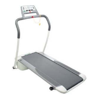
This service manual contains instructions and advice on service procedures with regard to Tunturi’s treadmill models J6 / J6F and J8 / J8F. The main objective of the service manual and the trouble shooting charts is to guide the service person to find the component or entity of components, which cause the malfunction. -
Page 6: Meters
The belt motor is controlled by PWM -adjustment. The lift motor is of DC type. J6 / J6F –models have three (3) four-digit LCD –displays. J8 / J8F –models have three (3) four- digit LCD -displays and a custom LCD –display module. -
Page 7: Controls Out The Equipment
In the service menu, the display in the centre shows the selected value of the page. 1.7.1 Page 1 Total values The display in the centre shows the total hours of use and the display on the right hand side shows the total distance. Copyright by Tunturi Oy Ltd All information subject to changes... -
Page 8: Lift Motor Calibration
The display in the centre shows the software version in use, e.g. 0.3. 1.7.7 Page 7 Start test profile The display in the centre shows ProF. Start the profile by pressing the + key. Copyright by Tunturi Oy Ltd All information subject to changes... -
Page 9: Electronics Module
(110° C), which releases if the transformer is overloaded. Basic information on the transformer: 115 / 230 VAC primary 18 VAC secondary 50 VA power 110° C thermal protector Copyright by Tunturi Oy Ltd All information subject to changes... -
Page 10: Module Connections
On the back side: meter connection speed sensor connection thermal protector (J8) connection lift motor connection to the user interface to the speed sensor to the lift motor Copyright by Tunturi Oy Ltd All information subject to changes... -
Page 11: Cables, Main Switch And Safety Switch
Audio Left Not in use Audio Right Not in use Incoming async. Data. RS-232 –levels Outgoing async. Data. RS-232 –levels Programmable RS-output (no current feed to components) Signal Ground Shield Copyright by Tunturi Oy Ltd All information subject to changes... -
Page 12: Lift Motor And Lift Arm
Motor supply voltage (-) drive down Motor supply voltage (-) drive down Brown White Black Sensor pulse voltage +5 VDC Lilac Sensor pulse signals Chart 4-1 Lift motor cable colors and signals Copyright by Tunturi Oy Ltd All information subject to changes... -
Page 13: Replacing The Lift Motor
The lift arm is attached with screws to the side profiles of the frame. The lift arm can be removed by opening the screws and loosening the lift motor shaft. 4.2.2 Lift arm rollers The plastic rollers are locked to their shafts with a locking sleeve. Copyright by Tunturi Oy Ltd All information subject to changes... -
Page 14: Motor And Transmission
As in T-Track: 2-pin connector, which receives information from the motor’s thermal protector. The models J8 / J8F have the same motor as in T-Track, accordingly the thermal protector is the same. The motor of models J6 / J6F does not have the thermal protector. 5.1.3 Coal brushes The coal brushes (2 pcs) are replaceable and available as spare parts. -
Page 15: Wiring
5.1.4 Overload and Thermal Protector The J6 / J6F motor is equipped with an overload protector, which is located on the circuit board. If the motor is overloaded, the overload protector cuts the current to the motor. Under overload the belt movement becomes jerky. The most common reason to the overload is insufficient belt lubrication.watching the current limit. -
Page 16: Transmission
You can re-adjuste the tension of the drive belt: the belt must give way approximately 10 mm in the middle part when pushing it powerfully. Note that overtightness will eventually damage both to the belt and the shaft bracket of the motor. Copyright by Tunturi Oy Ltd All information subject to changes... -
Page 17: Eplacing And Adjusting The Drive Ightener
The tightener is attached to the frame with a flexible joint. Brackets of type 2x6203ZZ are used as tightener rolls. Only the complete belt tightener is available as a spare part. Copyright by Tunturi Oy Ltd All information subject to changes... -
Page 18: Main Frame
When replacing the rails, pay attention to the wiring inside the rail and to that of the meter. J6F and J8F models require the attachment of the FoldAway frame to the hand rails. This frame is not ready assembled, and the attachment takes place with screws (see Owner’s Manual). The FoldAway frame serves as a supporting element in storage position. -
Page 19: Rollers
Remove the rear roller cover. Remove the adjustment bolts of the roller shaft. The rear roller can only be removed after the front roller is removed so that the belt becomes loose enough. Copyright by Tunturi Oy Ltd All information subject to changes... -
Page 20: Eversing And Replacing
The running deck is made of Finnish plywood; the deck is coated with a phenolic sheet. This running deck material has proved to be the best in tests carried out by Tunturi and various partners. To ensure a comfortable running feeling, the running deck is attached to the frame with six elastic rubber bumpers. -
Page 21: B T R
300 hours of use. Relubrication is necessary, if the belt moves unevenly or the resistance is increased the motor heats up more than usually the overcurrent protector or thermal protector has cut off the motor (= overload) Copyright by Tunturi Oy Ltd All information subject to changes... -
Page 22: Ubrication Pipes
_____________________________________________________________________________________ Version 1/2000 The relubrication must be done at regular intervals, depending on the fashion and hours of use. For relubrication, only T-Lube must be used, as it is specifically developed for use with Tunturi treadmills. 8.4 Lubrication pipes The treadmill is equipped with 2 lubrication pipes, one on either side of the frame. T-Lube is sprayed through these pipes to the inside of the belt so that the center part of the belt becomes moist with T-Lube along the whole length. - Page 23 Foldaway-frame by removing the quick locking sleeves from the ends of the axle. The sleeves must be changed when replacing the gas spring. Copyright by Tunturi Oy Ltd All information subject to changes...
- Page 24 Faulty connections between control board and upper board or faulty control board. The control board changes information with the upper board in intervals of 50ms. If the upper board does not receive a signal for 1 second, this error code appears. Copyright by Tunturi Oy Ltd All information subject to changes...
- Page 25 Failure in saving the CUSTOM START target elevation / speed. Failure in reading the cumulative total distance. Failure in saving the cumulative total distance. Failure in reading the cumulative total time. Failure in saving the cumulative total time. Copyright by Tunturi Oy Ltd All information subject to changes...
- Page 26 Lift motor is overloaded. The control board contains a protective current measurement. In case the lift motor is mechanically jammed or overloaded in use, the thermal protector releases. Remove mechanical obstacles. Copyright by Tunturi Oy Ltd All information subject to changes...
- Page 27 (73/237/ EEC) North America: FCC requirements on electromagnetic compatibility J6 and J6F are designed to meet the EN precision and safety standards (Class A, EN-957, parts 1 and 6), ETL and TÜV Certificates pending. OTHER: Registered design...
- Page 28 6), ETL and TÜV Certificates pending. OTHER: Registered design Applied Tunturi patents: US 5518471 / Exercise treadmill with rearwardly placed incline mechanism FIN 982740 / Patent pending APPENDIX 1 / Page 2/(2) Copyright by Tunturi Oy Ltd All information subject to changes...
- Page 29 TUNTURI SERVICE MANUAL Version 1/2000 ______________________________________________________________________________________________________________________________________________ APPENDIX 2 / Page 1/(1) Copyright by Tunturi Oy Ltd All information subject to changes...
- Page 30 version 1/00 60 41 49 43 41 42 14 13 73 35 14 13...
- Page 31 version 1/00 60 41 49 43 41 42 10 14 13 73 35 14 13...
- Page 32 * - M8x25 DIN 7991 Screw, hand rail J6 9 103 4037 Front support J6F * - M8 DIN 137A Washer J6F * - M8x80 DIN 912 Screw J6F 10 103 4035 Rear support J6F 11 643 4004 Spring J6F...
-
Page 33: Belt
J6/J6F version 1/00, page 2/(3) - M8x10 ISO 7380 Screw 10.9, side rail - M8x25 DIN 7991 Screw, deck ( 2 pcs USA) 42 643 4005 Leaf spring, USA - M8x10 ISO 7380 Screw 10.9, side rail - M8x25 DIN 7991 Screw, deck... - Page 34 84 513 4003 Locking lever J6F - 4x40 DIN 7346 Pin J6F 93 533 7025 Plug, J6F - M5x14 DIN 7985 Screw J6F * 553 4013 Assembly kit (incl. *) * 556 031 Allen key 5 mm * 556 0001...
- Page 35 version 1/00 18 19 60 41 49 43 41 42 73 35 14 13...
- Page 36 version 1/00 18 19 43 41 42 10 14 13 73 35 14 13...
- Page 37 J8/J8F version 1/00, page 1/(3) 1 103 4034 Frame 2 233 4019 User interface (incl. 4) * - M5x12 DIN 912 Screw 3 173 4057 Meter lower cover Screw KB 40x12 WN-1441 4 233 4021 Membrane 8 543 4034 Hand rail bracket, pair J8 * - M6 DIN 125 Washer J8 * - M6x30 DIN 912 Screw J8...
- Page 38 J8/J8F version 1/00, page 2/(3) 38 533 4010 Rubber sheet 39 513 4002 Belt tightener frame 40 343 4010 Axle - 8 DIN 471 Retaining ring - M8 DIN 934 - M8x40 ISO 7380 Screw 41 533 4040 Rubber bumper (2pcs USA) - M8x10 ISO 7380 Screw 10.9, side rail (2pcsUSA)
- Page 39 J8/J8F version 1/00, page 3/(3) - M8x30 DIN 933 Screw, upper bracket/frame - M8x25 DIN 939 Screw, lower bracket - M8 DIN 125 Washer, bracket/fame - M8 DIN 985 Nut nylon, lower bracket 63 503 4020 Sensor bracket - M3x10 DIN 7985 Screw - M3 DIN 934 64 443 4011 Drive belt...