THUNDER TIGER mini Titan E325 Manual
Hide thumbs
Also See for mini Titan E325:
- Manual (63 pages) ,
- Assembly instructions manual (12 pages) ,
- Quick start manual (2 pages)
Table of Contents
Advertisement
Advertisement
Table of Contents

Related Manuals for THUNDER TIGER mini Titan E325


Summary of Contents for THUNDER TIGER mini Titan E325
-
Page 2: Table Of Contents
Titan E325 CONTENTS Introduction Other Items Required Assembling Section Main Rotor System Linkage Rod Installation Main Frame Assembly Tail Unit Assembly Tail Boom Bracket Set Electric System Canopy Assembly Main Rotor Blade Assembly Introduction of E-CCPM Control System Servo Connecting... -
Page 3: Introduction
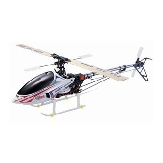
INTRODUCTION Thank you for purchasing the Thunder Tiger mini Titan E325 electric R/C helicopter. This new helicopter is the latest innovation by Thunder Tiger. It has the perfect combination of flying stability and the agility for 3D flying. This helicopter is an excellent choice for flying enthusiasts like you. - Page 4 FLIGHT SAFETY CHECKLIST 1.Make sure that the transmitter battery is fully charged before flying. 2.Make sure all control surfaces are operated properly before flying. 3.Do a range check of the radio before the first flight. The electronic equipment must operate properly at a range of at least 15 meters (50 ft) even with the transmitter antenna collapsed.
-
Page 5: Other Items Required
OTHER ITEMS REQUIRED RADIO SET Servos Transmitter Receiver Gyro (Control Surface x3, (helicopter type only, Rudder Servo x1) 6 or more channels) POWER SYSTEM Speed Control Li-Po Battery Battery Charger Brushless Motor TOOLS REQUIRED FOR ASSEMBLY Screw Driver Needle Nose Pliers Ball Link Pliers Nipper Scissors... -
Page 6: Assembling Section
ASSEMBLY The parts in the mini Titan E325 kit are packed according to the assembly steps. The part number and quantity are always shown in the square box on each page. Do not open all the bags at once. Open only the bag that is needed for the current... -
Page 7: Main Rotor System
Main Rotor-1 Bag A Material No. Description Material No. Description BV1083 Main Rotor Hub HNV2-6Z Shouldered Screw M2x6 BK1045 Seesaw Hub HMV520ZZW Bearing d2xD5x2.5 Step 1 Step 2 1.Slide in the Seesaw Hub to the Main Rotor 1.Turn the Seesaw Hub 90 degrees. Hub. - Page 8 Main Rotor-2 Bag A Material No. Description Material No. Description BK1046 BK1481 Flat Washer d2xD3.7x0.5 Mixing Lever BK1203 HMV520ZZW Bearing d2xD5x2.5 Linkage Ball (Ø3.8) HNU2-9Z HSP16-6N Countersunk Screw M1.6x6 Shouldered Screw M2x9 Step 1 Secure the Linkage Balls and fit the Bearings to the Mixing Lever.
- Page 9 Main Rotor-3 Bag B Material No. Description Material No. Description BK1044 BK1203 Linkage Ball (Ø3.8) Collar HSP16-6N HME3-3B Set Screw M3x3 Countersunk Screw M1.6x6 BK1015 BK0941 Flybar Paddle Flybar Control arm BK0916 Flybar Step 1 Step 2 1.Secure the Linkage Balls to the Flybar Control 1.Slide the Flybar through the Flybar Control Arm.
- Page 10 Main Rotor-4 Bag B Material No. Description Material No. Description HMV840ZZY Bearing d4xD8x3 BK1050 Main Rotor Pitch Housing HMO26 Flat Washer d2.8xD5x0.5 BK0906 Feathering shaft Flap Damper HMC 26-8B Socket Screw M2.6x8 BK1054 BK1203 Linkage Ball (Ø3.8) Collar BK1079 HSP16-6N Countersunk Screw M1.6x6 Thrust Bearing d4xD9x4 HMX0409Y...
- Page 11 Main Rotor-5 Bag B Material No. Description BK1051 Main Shaft BK1086 Socket Screw M2x14 HML2 M2 Nut Step 1 1.Slide the Main Rotor Hub Set on to the Main Shaft. 2.Mind the direction of the Main Shaft. 3.Fit the Screw and the Nut to fix the Main Rotor Hub and the Main Shaft.
- Page 12 Main Rotor-6 Bag C Material No. Description Material No. Description Countersunk Screw M1.6x6 BV1010A Swashplate HSP16-6N Main Shaft Lock Ring HNU2-9Z Shouldered Screw M2x9 BK1020 Set Screw M3x3 BK1058 Flybar Control Lever HME3-3B Bearing d2xD5x2.5 BK1481 Flat Washer d2xD3.7x0.5 HMV520ZZW Countersunk Screw M1.7x7 BK0914 Washout base...
-
Page 13: Linkage Rod Installation
Linkage Rod installation Bag D Material No. Description Material No. Description Ball Link 3.8x10mm Llinkage R od 1.3x10mm BK0932 BK1064 Llinkage Rod 1.3x7mm Llinkage R od 1.3x24.5mm BK1063 BK1066 Ball Link 3.8x12mm Llinkage R od 1.3x29mm BK0922 BK1065 Step 1 1.Assemble the Linkage Rods and the Ball Links. -
Page 14: Main Frame Assembly
Main Frame Assembly-1 Bag E Material No. Description Material No. Description Main frame Landing Skid BK1030 BK1059 Base Plate Tapping Screw(W/Washer) M2x6 BK1018 HNN2-6B Step 1 Assemble the Main Frame and the Base Plate with 6 self-tapping screws. Step 2 Attach the Landing Skid to the Base Plate with 4 self-tapping screws. - Page 15 Main Frame Assembly-2 Bag F Material No. Description Bearing d5xD11x5t HMV1150X Upper BRG Housing(left) BK1034 Upper BRG Housing(right) BK1033 Tapping Screw(W/Washer) M2x10 HNN2-10B Step 1 Assemble the Upper BRG Housing. Step 2 1.Slide the Upper BRG Housing into the Main Frame. 2.Fix the Upper BRG Housing with 4 self-tapping screws.
- Page 16 Main Frame Assembly-3 Bag F Material No. Description Material No. Description Servo Mount(Right) HNN2-6B Tapping Screw(W/Washer) M2x6 BK1048 Servo Mount(Left) BK1021 Battery Tray BK1049 Frame Spacer BK1022 BK1056 Battery Tray Side Plate Canopy Retaining Post BK1023 Battery Holder BK1057 Tapping Screw(W/Washer) M2x10 BK1037 Phasing Control Track HNN2-10B...
- Page 17 Main Frame Assembly-4 Bag G Material No. Description BK0933 Autorotation Tail Drive Gear Main Gear (W/Bearing) BV0934 BK0931 Flat Washer d6xD10x0.3 BK0930 One Way Bearing Shaft 1.The One Way Bearing and the Spacer are pre-assembled. 2.Assemble the Main Gear and the Autorotation Tail Drive Gear with the One Way Bearing Shaft.
- Page 18 Main Frame Assembly-5 Bag G Material No. Description HMC2-14B Socket Screw M2x14 M2 Nut HML2 HME3-3B Set Screw HMV1150X Bearing d5xD11x5 Main Shaft Lock Ring BK1020 1.Install the Bearing into the Base Plate. 2.Slide the Main Gear Assembly into the Main Frame. 3.Slide the Main Shaft through the Upper BRG Housing, the Main Gear Assembly and the Lower Bearing.
-
Page 19: Tail Unit Assembly
Tail Unit Assembly-1 Bag H Material No. Description Material No. Description Tail Boom 356mmxØ14 Tail Rotor Shaft Set BK1004 BV0973 Belt MXL-3tx413T Bearing d3xD8x4t BK1073 HMV830ZZ Tail Unit Housing Tapping Screw(W/Washer) M2x10 BK0988 HNN2-10B Tail Unit Housing Cover BK0989 Step 1 Insert the Tail Rotor Drive Belt through the Tail Boom so that it comes out of both ends. - Page 20 Tail Unit Assembly-2 Bag H Material No. Description Material No. Description BK0990 Tail Pith Control Lever-1 HMC2-16B Socket Screw M2x16 Tail Pith Control Lever-2 Tapping Screw(W/Washer) M2x10 BK0991 HNN2-10B Tail Pith Control Set Linkage Ball(Ø3.8) BV0993A BK1203 BK1091 Double Joint Lever HSP16-6N Countersunk Screw M1.6x6 Bearing d2xD5x2.5...
- Page 21 Tail Unit Assembly-3 Bag I Material No. Description Material No. Description BK0998 Tail Pitch housing BK1080 Safty Washer HMV840ZZY Bearing d4xD8x3 HMC2-8B Socket Screw M2x8 BK1000 Tail Pitch Control Link HNU2-9Z Shouldered Screw M2x9 BK0972 Tail Rotor Hub BK0961 Tail Rotor blade HMV520ZZW Bearing d2xD5x2.5 Step 1...
- Page 22 Tail Unit Assembly-4 Bag I Material No. Description HME3-3B Set Screw HNU2-9Z Shouldered Screw M2x10 Step 1 Secure the Tail Rotor Hub Set onto the Tail Rotor Shaft. Make sure that the Set Screw should be right on the dot of the shaft. Do not forget apply Loctite on the Set Screw.
- Page 23 Tail Unit Assembly-5 Bag I Material No. Description BK1085 Stabilizer Fin BK1001 Vertical Fin Tapping Screw(W/Washer) M2x6 HNN2-6B Tapping Screw(W/Washer) M2x10 HNN2-10B Step 1 1.Secure the Stabilizer Fin to the Vertical Fin. 2.Secure the Vertical Fin to the Tail Unit Housing. Step 2 Complete -22-...
-
Page 24: Tail Boom Bracket Set
Tail Boom Bracket Set-1 Bag J Material No. Description BK1005 Tail Boom Bracket BV1007 Tail Drive Gear Set BK1006 Tail Boom Bracket Cover HMJ2-10N Tapping Screw M2x10 Step 1 1.Fit the Tail Drive Gear Set to the Tail Boom Bracket. 2.Secure the Tail Boom Bracket Cover to the Tail Boom Bracket. - Page 25 Tail Boom Bracket Set-2 Bag J Material No. Description HMC2-12B Socket Screw M2x12 HML2 M2 Nut Step 1 1.Pull the belt through the Tail Boom Bracket and keep the belt correctly aligned. 2.Push the Tail Boom into the Tail Boom Bracket and the Tail Drive Belt must be rotated as shown below.
- Page 26 Tail Boom Bracket Set-3 Bag J Material No. Description BK1082 Rod Guide HMJ12-6B Tapping Screw M1.2x6 BK0923 Tail Servo Tray HNN2-10B Tapping Screw(W/Washer) M2x10 Step 1 1.Install the Rod Guides and the Tail Servo Tray. 2.Secure the self-tapping screws but not tighten them at this moment so that you can adjust later.
- Page 27 Tail Boom Bracket Set-4 Bag J Material No. Description Material No. Description HNN2-10B Tapping Screw(W/Washer) M2x10 BK1026 Bracket HMC2-25B Socket Screw M2x25 HMC2-14B Socket Screw M2x14 HML2 BK1025 M2 Nut Rod End BK1027 Tail support Rod Step 1 1.Slide the Tail Boom Set into the Main Frame. 2.Push it on the bracket instead of pushing the Tail Boom.
-
Page 28: Electric System
Gear to the Motor Mount should be around 16mm as shown. Note:1 1.The OBL 29/35-10H(No.2381) Brushless Motor and 13T pinion are recommended for mini Titan E325 with ACE POWER 3S1P Li-Po battery. 2.The OBL 29/35-10H(No.2381) Brushless Motor and 15T pinion are recommended for mini Titan E325 with ACE POWER 2S1P Li-Po battery. - Page 29 Electric System-2 Step 1 1.Remove the servo wheel prior to attaching the Linkage Ball. 2.Mount the Linkage Ball at 12.5mm from the center of the servo arm. 3.Secure the servo to the right Servo Tray and attach the rod to the servo arm. Step 2 1.Remove all the servo wheels prior to attaching the Linkage Balls.
- Page 30 Electric System-3 Bag L Material No. Description BK1071 Tail Linkage Rod D1.3 BK0922 Ball Link 3.8x12mm BK1203 Linkage Ball( 3.8) HSP16-6N Countersunk Screw M1.6x6 Step 1 1.Remove the tail servo wheel prior to attaching the Linkage Ball. 2.For the rudder servo, mount the Linkage Ball at 10.5mm from the center of the servo arm as beginning.
- Page 31 Electric System-4 Bag L Material No. Description BK1028 Antenna Tube BK1088 Rubber Tube 10mm BK1038 Landing Skid Damper Step 1 1.Attach the receiver, gyro to the Main Frame by Double Side Tap. 2.Insert the Antenna Tube and fix it by the Rubber Tube. Gyro Double Side Tap Receiver...
-
Page 32: Canopy Assembly
Canopy Assembly Bag M Material No. Description BK1087 Canopy BK1076 Body HMJ12-3B Tapping Screw M1.2x3 BK1002 Rubber Grommet Step 1 1.Cut off the unnecessary part from the body and the canopy. 2.Attach the canopy to the body by 3 self-tapping screws. 3.Insert the Rubber Grommet to the body as shown. -
Page 33: Main Rotor Blade Assembly
Main Rotor Blade Assembly Material No. Description Note: BK1061 Main Rotor Blade BK1067 Upper Blade Grip Lower Blade Grip BK1068 Countersunk Screw M1.6x6 HSP16-6N HMC3-20B Socket Screw M3x20 M3 Nylon nut HMM3Z Sticker for C.G JD0451 Step 1 1.For safety concern, be sure to modify the main blades as following. 2.Mark around the blade grips with a felt tip marker. -
Page 34: Introduction Of E-Ccpm Control System
INTRODUCTION OF E-CCPM CONTROL SYSTEM The E-CCPM(Electric Cyclic/Collective Pitch Mixing) system offers the users a control system that can accomplish the same control as traditional M-CCPM(Mechanical Cyclic/Collective Pitch Mixing) system, but with simple machinery. The 120°∘ E-CCPM system utilizes 3 servos for the main control of aileron, elevator and collective pitch. - Page 35 MOVEMENT OF 120°∘ E CCPM SYSTEM The given inputs are executed by the team work of the 3 servos through the mixing program of the radio or the electronic mixer. The following are the examples showing how the movement be carried out.
- Page 36 MOVEMENT OF 120°∘ E CCPM SYSTEM ELEVATOR The elevator is controlled by all of the 3 servos. When an elevator command is given, the 2 servos in the front move in the same direction and the third one move contrary. For example, when a down elevator command is given, the 2 front servos pull the swashplate downward and the third one push the swashplate upward so that the down elevator command is executed.
-
Page 37: Servo Connecting
SERVO CONNECTING E-CCPM system requires 3 channel for aileron, elevator and an AUX(for pitch). But people may get confused because the 3 channels are not referred to any independent movement. They are operated together to carry out the rolling, flipping and collective controlling. As a result, the following connecting manner is recommended. - Page 38 BASIC CONCEPT OF ADJUSTMENT Because people may be confused with the operating manner of the E-CCPM system, we want to explain the basic concept of how to center and trim the servo while adjusting the full travel distance. First of all, we have to make it clear about what do you want to adjust. Do you want to adjust the servo itself or the control surface? For example, if you want to adjust the servo which is plugged into the aileron channel itself, only the servo will be adjusted.
-
Page 39: Concept Of Basic Setting And Adjustment
CONCEPT OF BASIC SETTING AND ADJUSTMENT Before starting, make sure the following preparation is done. 1. Set all trims, knobs, and switches to the neutral and zero position. 2. Reset the radio to its factory preset position. 3. Choose the 120°∘ E-CCPM swashplate control mode. Reversing/Swash Mixing The moving direction of servos has to be confirmed. - Page 40 CONCEPT OF BASIC SETTING AND ADJUSTMENT Level the Swashplate After centering the servos, setting the length of the control linkages and attaching them to the link balls, it is important to check the swashplate that it is level. Turn on the transmitter and the receiver, do not connect the Motor at this moment, and center the collective pitch stick.
- Page 41 COLLECTIVE TO CYCLIC MIXING ADJUSTMENT It always happens that the travel of each servo varies slightly. If so, the swashplate would be tilted when giving a full collective pitch command. These variations can be corrected by altering the travel value of each servo slightly by using the “Travel Adjustment” function. Pitch to Aileron Mixing Place the collective stick to the full positive pitch position.
- Page 42 COLLECTIVE TO CYCLIC MIXING ADJUSTMENT Pitch to Elevator Mixing Through the previous step, we’ve got rid of the pitch to aileron mixing. It is as important to vanish the pitch to elevator mixing. Place the collective stick to the full positive pitch position. Check the swashplate from a side of the model to insure if it’s level from head to rear.
-
Page 43: Setting Up Of Linkage
SETTING UP OF LINKAGE The lengths of the linkage rods are recommended as the following: 18mm 41.5mm 23mm 20mm 36.5mm Lengths are measured from ball link center to ball link center. The pushrod length above is suitable for beginner and 3D flying. You can use those lengths as the starting setting, and adjust the lengths for your flying style. - Page 44 SETTING UP MAIN ROTOR COLLECTIVE PITCH ANGLE Main Frame Assembly-2 Since you have been setting the lengths of the pushrod as mentioned, the linkage should be centered well as described below. Centering 1. The levers should be as the drawing below while centering the collective pitch stick.
-
Page 45: Pitch Curve
SETTING UP DATA FOR YOUR REFERENCE The following is the setting up data of pitch curve and throttle curve for your reference only. Please ask experienced pilot to help you if you have never done this before. Beginner Throttle Curve Pitch Curve Throttle Curve Thro. - Page 46 TAIL CONTROL AND GYRO SETUP It is recommended to use a Heading Hold Gyro. With a Heading Hold Gyro, you may not use the trim and the revolution mixing function of tail control. First, choose the length of the tail servo arm referring to the manual of the Gyro.
- Page 47 USING OF LI-PO BATTERY The mini Titan E325 is an electric RC helicopter. It is strongly recommended to use Lithium Polymer Battery. Please refer to the following information and precaution: 1. Do use a charger that is designed for Li-Poly batteries only.
-
Page 48: Trouble Shooting
TROUBLE SHOOTING Helicopters Q: What would you check when the helicopter shakes during flying? Are the main blades out of track? Are the paddles out of track? Are the main blades well balanced? Are the paddles well mounted at the same distance from the rotor shaft? Is the spindle or the flybar bent? Is the main shaft bent? - Page 49 TROUBLE SHOOTING The pinion would be 150T / 11.1 = 13.51 So we choose 13T as the motor pinion. IF using a 2S(7.4V) Li-Po battery for long time hovering, the motor rpm should be 3500KV x 3.7V x 2S x 0.8= 20720 rpm And we expect to have the hovering head speed of 2100rpm 20720 / Gear Ratio = 2100 Gear Ratio = 9.87...
-
Page 50: Spares Parts
E325 SPARE PARTS PV0701 PV0702 PV0703 PV0704 MAIN ROTOR HUB FLYBAR SEESAW HUB FLYBAR CONTROL LEVER MAIN SHAFT(2) PV0705 PV0706 PV0707 PV0708 MAIN ROTOR GRIP FLAP DAMPER(70°) FEATHERING SHAFT(2) FLYBAR CONTROL ARM PV0709 PV0710 PV0711 PV0712 FLYBAR(2) SWASHPLATE WASHOUT BASE SET MIXING LEVER PV0713 PV0714... - Page 51 PV0725 PV0726 PV0727 PV0728 M.G. HEX DRIVE HUB ONE WAY SHAFT M. SHAFT LOCK RING(2) MOTOR MOUNT PV0729 PV0731 PV0732 PV0733 PINION 13T(2) PINION 15T(2) TAIL BOOM BRACKET TAIL DRIVE GEAR SET PV0734 PV0735 PV0736 PV0737 TAIL BOOM(2) TAIL DRIVE BELT, MXL413T TAIL UNIT CASE SET TAIL ROTOR SHAFT(2) PV0738...
- Page 52 PV0750 PV0751 PV0752 PV0753 TAIL P. CONTROL SLIDER TAIL SUPPORT BRACKET TAIL SUPPORT TAIL LINKAGE ROD (12) PV0754 PV0755 PV0756 PV0757 LINKAGE ROD SET BALL LINK, 3.8 BODY SET CANOPY PV0761 PV0758 PV0759 PV0760 THREADLOCKING, T22 BODY ONLY BLADE HOLDER ANAEROBICS RETAINER, R48 (20) PV0762...
- Page 53 (10) (10) (20) (20) (20) PV0774 PV0775 PV0776 PV0777 SHOULDERED SCREW, M2x9 SOCKET SCREW(20), M2x14 SOCKET SCREW(20), M2x16 SOCKET SCREW(20), M2x8 (20) (20) (20) PV0778 PV0779 PV0780 PV0781 SOCKET SCREW(20), M2x10 SOCKET SCREW(20), M2x25 SET SCREW(20),M3x3 SCREW BAG (20) (20) (20) PV0782 PV0234...
- Page 54 NAME Quantity PV0701 MAIN ROTOR HUB PV0702 SEESAW HUB FLAT WASHER, d2xD3.7x0.5t SHOULDERED SCREW, M2x9 SHOULDERED SCREW, M2x6 PV0703 FLYBAR CONTROL LEVER WASHOUT LINKAGE LINKAGE BALL(Ø3.8) SHOULDERED SCREW, M2x9 FLAT WASHER, d2xD3.7x0.5t COUNTERSUNK SCREW, M1.7x7 COUNTERSUNK SCREW, M1.6x6 PV0704 MAIN SHAFT SOCKET SCREW, M2x14 HEX NUT, M2 PV0705...
- Page 55 NAME Quantity SERVO TRAY(LEFT) TAPPING SCREW (W/WASHER), M2x6 TAPPING SCREW (W/WASHER), M2x10 PV0719 BATTERY SIDE FRAME BATTERY TRAY BATTERY HOLDER TAPPING SCREW (W/WASHER), M2x6 TAPPING SCREW (W/WASHER), M2x10 PV0720 FRAME SPACER CANOPY RETAINING POST PV0721 PHASING CONTROL TRACK TAPPING SCREW (W/WASHER), M2x6 PV0722 AUTO-R TAIL DRIVE GEAR PV0723...
- Page 56 NAME Quantity PV0742 TAIL ROTOR PV0743 STABILIZER FIN VERTICAL FIN TAPPING SCREW (W/WASHER), M2x6 TAPPING SCREW (W/WASHER), M2x10 PV0744 FLYBAR PADDLE PV0745 MAIN ROTOR BLADE, 315mm PV0746 SKID DAMPER PV0747 TAIL SERVO TRAY TAPPING SCREW (W/WASHER), M2x10 PV0748 DOUBLE JOINT LEVER SOCKET SCREW, M2x16 FLAT WASHER, d2xD3.8x0.5t PV0749...
- Page 57 NAME Quantity PV0771 BEARING, d4xD9x4t PV0772 TAPPING SCREW (W/WASHER), M2x6 PV0773 TAPPING SCREW (W/WASHER), M2x10 PV0774 SHOULDERED SCREW, M2x9 FLAT WASHER, d2xD3.8x0.2t PV0775 SOCKET SCREW, M2x14 PV0776 SOCKET SCREW, M2x16 PV0777 SOCKET SCREW, M2x8 PV0778 SOCKET SCREW, M2x10 PV0779 SOCKET SCREW, M2x25 PV0780 SOCKET SCREW, M3x3 PV0781...
-
Page 58: Optional Parts
E325 OPTIONAL PARTS PV0730 PV0801 PV0802 PV0803 PINION 10T(2)(FOR 2.3mm SHAFT) METAL M. ROTOR HUB HARDENED MAIN SHAFT METAL ROTOR GRIP PV0805 PV0806 PV0807 PV0804 METAL SEESAW HUB METAL MIXING LEVER M. FLYBAR C. ARM M. FLYBAR C. LEVER PV0808 PV0809 PV0810 PV0811... -
Page 59: Heli Accessories
PV0829 PV0830 PV0831 PV0832 ROTOR SPACER(FOR 5mm BLADE ROOT) PINION 11T(d2.3) PINION 11T(d3.17) PINION 12T PV0834 PV0835 PV0836 PV0833 PINION 14T CARBON BATTERY TRAY VELCRO BODY(PELLUCID) 3846 3851 GLASS FIBER MAIN BLADES, 325mm CARBON MAIN BLADES, 325mm E325 ACCESSORIES 2532 2808 1198 2381... -
Page 60: Specifiction And Features
SPECIFICATION Fuselage length: 654 mm (25.74 in) Fuselage width: 120mm (4.72 in) Total height: 210mm (8.3 in) Main rotor dia.: 728mm (28.66 in) / Max.748mm (29.45 in) Tail rotor dia.: 156mm (6.14 in) Gear ratios: 1 : 10 : 4.4 1 : 11.5 : 4.4 1: 15 : 4.4 Full equipped weight:... - Page 61 -60- JK0201 V4...