Table of Contents
Advertisement
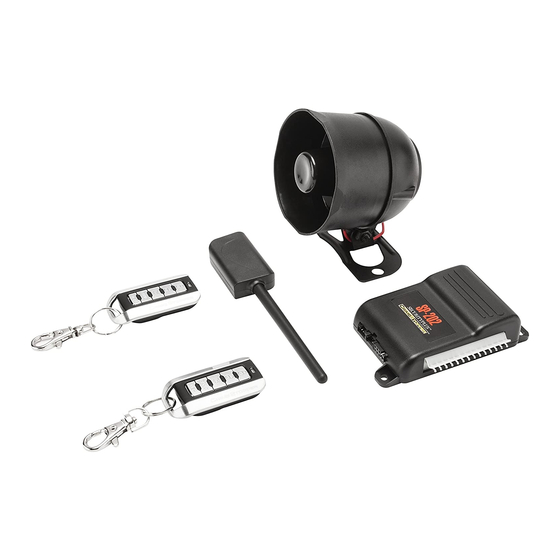
CS-872 / SP-202 and SP-302
KEYLESS ENTRY and ALARM SYSTEM
CONGRATULATIONS on your choice of a Remote Keyless Entry and Alarm System by Crimestopper
Security Products Inc. This booklet contains the information necessary for installing, using, and maintaining
your alarm system. If any questions arise, contact your installation dealer or Crimestopper Security Products
Inc. at the Tech Support number below.
*IMPORTANT INFORMATION:
This system can be configured to operate as a Keyless Entry, 1-Way Alarm or 2-Way Paging Alarm System.
The type of system is option selectable (option #17). When selecting keyless entry, all features operate except
the alarm triggers are disabled.
This installation book is designed for the installer or individual with an existing understanding of
automotive electrical systems, along with the ability to test and connect wires for proper operation.
To ease installation, we suggest that you READ THIS MANUAL before beginning your installation.
This book is provided as a GENERAL GUIDLINE and the information contained herein may differ from
your vehicle.
TECH SUPPORT
Mon-Fri 8:00 AM-4:30 PM Pacific Time
(800) 998-6880
REV.
10-2012
INSTALLATION INSTRUCTIONS
INTRODUCTION
This device complies with FCC Rules part 15. Operation is subject to
the following two conditions: 1) This device may not cause interference,
and (2) this device must accept any interference that may be received,
including interference that may cause undesired operation.
manufacturer is not responsible for any radio or TV interference caused
by unauthorized modification to this equipment. Such modification
could void the user's authority to operate the equipment.
The
Advertisement
Table of Contents

Related Manuals for CrimeStopper CS-872


Summary of Contents for CrimeStopper CS-872
- Page 1 CONGRATULATIONS on your choice of a Remote Keyless Entry and Alarm System by Crimestopper Security Products Inc. This booklet contains the information necessary for installing, using, and maintaining your alarm system. If any questions arise, contact your installation dealer or Crimestopper Security Products Inc. at the Tech Support number below.
-
Page 2: Table Of Contents
TABLE OF CONTENTS Installation Cautions & Warnings..…….……………………………….……………………………………….……2 Control Module & Component Mounting ……………...……………………..……………………….…….…..…..3 LED and Valet Programming Button………………………………………………………………………………….3 Wiring………………………………………………………………………..…………………..………….….…….….4-5 Starter Kill Wiring………………………………………………………………………..…………………..…………..6 Power Door Lock Wiring……………………………………………………….………………………….…...….…7-8 Passenger Door Unlock Wiring………………...……………………………….………………………….…...….…9 Transmitter Programming………………………………………………………………………………….…………10 Option Programming…………………………………………….…….………………….…….…………...….…11-15 SHOCK SENSOR Wiring…….…………….………….….…..…………………………………………………….…16 Wiring Diagram..…………………………………………………..……………………………..……………..………17 Antenna Diagram..………………………………………………..……………………………..……………..………18 Data Port Diagram …………………………………………………………………………………………………..…19 INSTALLATION CAUTIONS &... -
Page 3: Control Module & Component Mounting
CONTROL MODULE & COMPONENT MOUNTING DO NOT Mount the control module in the engine compartment or where the wiring harness can become entangled with moving parts such as brake/gas/clutch pedals, or the steering column! The alarm control module should be mounted in a concealed location. The Placement of the module will affect the distance from which the remote transmitter can control the unit. -
Page 4: Wiring
WIRING GREEN WIRE: (-) NEGATIVE DOOR TRIGGER Identify the wire that reads ground when any door is open and 12 volts when all doors are closed. Some vehicles may have isolated door triggers. In this case you may need to run additional wires from other doors or go directly to the wire that triggers the vehicle’s interior dome light. -
Page 5: Wiring
WIRING BLACK/WHITE WIRE: (-) NEGATIVE DOME LIGHT ILLUMINATION OUTPUT (Optional, requires a relay) This wire provides a (-) negative ground when the system is disarmed to activate a vehicles dome light circuit. We recommend the use of a relay for this connection. Connect Black/White to terminal #85 of relay. Connect terminal #86 to fused constant +12V. -
Page 6: Starter Kill Wiring
STARTER KILL WIRING ORANGE WIRE: (-) NEGATIVE ARMED OUTPUT (500mA Ground, Optional) This wire should be connected to the Yellow wire of the pre-wired relay socket for the starter disable. Connect the White wire of the relay socket to the Ignition switched wire on the vehicle. Cut the vehicle starter wire and connect each half to a Green wire on the relay socket. - Page 7 POWER DOOR LOCKS: WIRING & SYSTEM TYPES PIN 1: BLUE: (-) Negative pulse for UNLOCK Crimestopper Door Lock Accessories: PIN 2: RED: 12V When using external relays (TERM 86) CS-6600DLM: Dual-relay plug-in module for Reverse PIN 3: GREEN: (-) Negative pulse for LOCK Polarity, Positive, or Aftermarket Motors.
-
Page 8: Power Door Lock Wiring
POWER DOOR LOCK WIRING NEGATIVE TRIGGER DOORLOCK WIRING POSITIVE TRIGGER DOORLOCK WIRING GREEN GREEN FUSED +12V BLUE BLUE FACTORY FACTORY POWER POWER LOCKING LOCKING RELAYS RELAYS REVERSE POLARITY DOOR LOCK WIRING AFTERMARKET MOTOR/DOOR LOCK WIRING GREEN GREEN FUSED FUSED +12V +12V BLUE BLUE... -
Page 9: Passenger Door Unlock Wiring
SEPARATE DRIVER’S DOOR UNLOCK WIRING NEGATIVE TRIGGER DOOR LOCKS BLUE/WHITE GREEN BLUE DRIVER'S DOOR MOTOR FACTORY LOCK RELAYS +12V FUSED UNLOCK WIRE WIRING FOR REVERSE POLARITY DOOR LOCKS BLUE/WHITE GREEN FUSED +12V BLUE MASTER SWITCH 30 87A LOCK WIRE UNLOCK WIRE... -
Page 10: Transmitter Programming
TRANSMITTER PROGRAMMING NOTE: All transmitters must be learned at the time of programming. This system can learn up to 4 remotes. 1. Turn key to the ON position and press program button 4 times. 2. After a short delay, the unit will flash the parking lights 4 times; Siren 4 times, Horn 4 times and status LED will be on solid. -
Page 11: Option Programming
OPTION PROGRAMMING 1. Turn the Ignition ON and press the Valet/Program button 5 times. 2. After a short delay, the parking lights will flash 5 times, Siren and Horn 5 times and status LED will be on solid. 3. Within the next few seconds, press the Valet/Program button [again] the number of times that corresponds to the options chart below. - Page 12 TX Button #1 - TX Button #2 - Unlock TX Button #3 - TX Button #4 - Option Description Option # Lock Trunk Panic *Default* Arm & Disarm thru OEM *OFF* Remote (data mode only) Arm/Disarm with IGN ON *OFF* White/Red Wire Selection Aux 2 Output *OEM Disarm*...
- Page 13 PROGRAMMABLE OPTIONS Cont. 5. PASSIVE ARMING This option is used to automatic arm the alarm system 30 seconds after the ignition is tuned off and the last door is closed. If a door is reopened during the 30 second countdown, the system will wait and begin the countdown again after the door is closed.
- Page 14 PROGRAMMABLE OPTIONS Cont. 9. PARKING LIGHTS ON WITH DISARM or UNLOCK: Keeps parking lights 30 seconds when system is disarmed to assist in locating and providing illumination near your vehicle when approaching at night for safety. 10. TRUNK RELEASE SELECTION: To eliminate the possibility of accidentally opening the trunk, there are (3) options for button press selection.
- Page 15 PROGRAMMABLE OPTIONS Cont. 15. ARM / DISARM with IGNITON ON: This option allows you Arm and Disarm the system with the Ignition ON. This is used when there is a remote starter added to the system. The Default = Off. Lock/unlock without arm and disarm while the ignition on. 16.
-
Page 16: Shock Sensor Wiring
WIRING: 4-PIN Shock Sensor (22 Gauge wires) SHOCK SENSOR: The sensor supplied with this system does not require any additional wiring. Simply mount the sensor in a suitable location, plug it in, and adjust the sensitivity. There are 2 LED’s on the shock sensor to assist you in adjusting sensitivity. -
Page 17: Wiring Diagram
WIRING DIAGRAM Valet / Program Button STATUS LED (-) Unlock Output BLUE +12 Volts for Relays (-) Lock Output GREEN Shock Sensor ANTENNA DATA PORTS (-) Door Pin Switch FUSE +12V POWER Parking BATTERY Lights (+) Door Pin Switch GREEN (+) WHITE (-) Door Trigger 10A MAX... -
Page 18: Antenna Diagram
ANTENNA DIAGRAM ANTENNA MODULE: For optimum range and performance, the antenna should be located high up on the front windshield glass. For example: behind the rearview mirror. Note: Window tints or Films may decrease the range of the system. The mounting surface for the antenna should be clean and dry. ANTENNA LOCATIONS WINDSHIELD... -
Page 19: Data Port Diagram
DATA PORT DIAGRAM This unit includes DP Technology that will allow you to directly Plug-In our Data Port Bypass Modules. There are 2 types of Protocol, ADS - OFA Series and EVO - SL series modules. The default is set for EVO - SL Series Protocol. - Page 20 Phone (800) 998-6880 ONLINE TECHNICAL SUPPORT FAX (805) 581-9500 www.crimestopper.com © 2012 Crimestopper Security Products...