Advertisement
CONGRATULATIONS on your choice of a CrimeStopper Remote Security System. This booklet contains all the
necessary information for using, and installing your security system. If any questions should arise, contact
CrimeStopper technical support at 1-800-998-6880 or check out the Knowledge Base at www.crimestopper.
com.
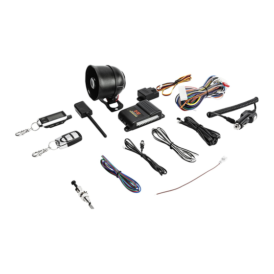
ONE-WAY
DELUXE
SECURITY
SYSTEM
INSTALLATION MANUAL
Advertisement
Table of Contents

Related Manuals for CrimeStopper SP-102


Summary of Contents for CrimeStopper SP-102
- Page 1 SECURITY SYSTEM CONGRATULATIONS on your choice of a CrimeStopper Remote Security System. This booklet contains all the necessary information for using, and installing your security system. If any questions should arise, contact CrimeStopper technical support at 1-800-998-6880 or check out the Knowledge Base at www.crimestopper.
-
Page 2: Pre-Installation
TABLE OF CONTENTS Pre-Installation We suggest that you read the entire manual prior to starting your installation. This manual is a general guideline as our product is universal and your installation may differ from vehicle to vehicle. Check all of the vehicle’s manufacture warnings and cautions regarding electrical service (air bags, abs, brakes, engine/body computers and battery) We recommend you find and test all wiring prior to prepping and installing the product. -
Page 3: Cautions And Warnings
CAUTIONS AND WARNINGS Cautions and Warnings • Damage resulting from improper installation is not covered under warranty. • Do not start the vehicle in an enclosed area without proper ventilation. • Do not route any wiring where it may become entangled. •... - Page 4 WIRING BLACK WIRE: CHASSIS GROUND - The BLACK wire MUST be attached to a paint-free surface of solid metal. YELLOW WIRE: SWITCHED IGNITION - Connect this wire to an IGNITION wire. The IGNITION wire will show 12 Volts when the IGNTION switch is in the ON position as well as in the START position.
-
Page 5: Wiring Diagram
This output is used for disabling the starter or to activate the optional devices such as extra sensors, LED’s, window roll-up modules, voice modules, etc. COMPONENT MOUNTING Wiring Diagram SP-102 Connector Side View Single/Double Pulse Electric/Vacuum Electric or Vacuum Locks... - Page 6 DOOR LOCK WIRING Door Lock Wiring – 3 Pin Harness Blue/White - Pulse for unlock- negative output Green/White - Pulse for lock- negative output How to determine which door locks the vehicle has- It is recommended to learn which style of door locks the vehicle has prior to connecting any wires.
-
Page 7: Shock Sensor
SHOCK SENSOR Shock Sensor 4 Pin Harness The shock sensor is what tells the alarm that something has struck the vehicle or is trying to break in. The system has 2 leds and 2 adjustment dials on it. The I LED is for pre-warn while the II LED is for full alarm trigger. For a more sensitive alarm turn the dials to the right. -
Page 8: Programming Options
PROGRAMMING OPTIONS Option Programming • Turn the ignition ON and press the Override/Program button 5 times. After a slight delay, the system will chirp and flash the parking lights 5 times. • Within the next few seconds, press the Override/Program button the number of times that corresponds to the feature list below. The system will chirp for each button press. - Page 9 PROGRAMMING OPTIONS EXPLAINED HORN CHIRP PULSES - This option controls the system’s Horn-honk output. There are 3 selections: Button 1 (LOCK) Horn pulse only when alarm is triggered. Button 2 (UNLOCK) Horn chirps for Arm, Disarm, Single Pre-warn protection and full trigger alarm. Button 3 (SILENT) Horn chirps for Arm, Disarm, Multiple Pre-warn protection and full trigger alarm.
-
Page 10: Carjack Modes
PROGRAMMING OPTIONS PARKING LIGHTS ON WITH DISARM - With this feature enabled, the parking lights will flash twice and then stay on for 30 Seconds when the system is disarmed. This is for added security and to assist in locating your vehicle in a crowded parking lot. The parking lights will stay on for 30 Seconds or until the ignition is turned ON. - Page 11 PROGRAMMING OPTIONS EXPLAINED FULL-TIME CARJACK Full-time Carjack mode should only be used in extreme conditions. This feature provides Full-time Carjack protection and MUST be enabled before use through the alarm programming. Every time the ignition is turned ON OR a door is opened the Carjack countdown will be initiated.
-
Page 12: Remote Pairing
A quick note before you begin. Once you enter programming mode it will erase all of the other remotes paired to the system, therefore we recommend having all remotes for the system ready to pair prior to entering pairing mode. The SP-102 can pair up to 4 remotes. - Page 13 For more information about relays, immobilizers, wire isolation, diodes and more head over to crimestopper.com then click the Support tab then on the Knowledge Base tab. This will take you to the home page of the CrimeStopper Knowledge Base. Once here, under the heading of Featured Support Categories click on the Install/Troubleshoot tab.
-
Page 14: Limited Warranty
Length Of Warranty Limited Lifetime, CrimeStopper will repair or replace defective modules with a comparable new or refurbished module during reasonable usage and the lifetime of the vehicle in which it is originally installed provided that the module is returned to Rockford, shipping pre-paid and accompanied by a legible copy of the original sales receipt from the authorized dealer containing;...