Table of Contents
Advertisement
Quick Links
Advertisement
Table of Contents

Related Manuals for Datavideo BC 80


Summary of Contents for Datavideo BC 80
-
Page 2: Table Of Contents
Table of Contents FCC COMPLIANCE STATEMENT ........4 WARNINGS AND PRECAUTIONS........4 WARRANTY ..............5 ............5 TANDARD ARRANTY ............5 ARRANTY DISPOSAL ..............6 1. INTRODUCTION ............7 ................ 7 EATURES 2. SYSTEM DIAGRAM............ 8 3. CONNECTIONS............9 ..............9 RONT .............. - Page 3 Datavideo Technologies is not responsible for any omissions or errors, or for any subsequent loss or damage caused by using the information contained within this manual.
-
Page 4: Fcc Compliance Statement
This product should only be operated from the type of power source indicated on the marking label of the AC adapter. If you are not sure of the type of power available, consult your Datavideo dealer or your local power company. -
Page 5: Warranty
Warranty Standard Warranty • Datavideo equipment is guaranteed against any manufacturing defects for one year from the date of purchase. The original purchase invoice or other documentary evidence should be • supplied at the time of any request for repair under warranty. -
Page 6: Disposal
Hard Drives are only covered for the first 10,000 hours, or 1 year (whichever comes first). Any second year warranty claims must be made to your local Datavideo office or one of its authorized Distributors before the extended warranty expires. -
Page 7: Introduction
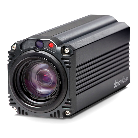
1. Introduction The BC-80 Block Camera is a small HD camera with an infra-red remote control. It can be used for HD high quality shooting in an environment where space is limited. The image resolution is 1920x1080. The BC-80 provides 30x optical focus, and the image output interfaces are SDI and HDMI. -
Page 8: System Diagram
2. System Diagram... -
Page 9: Connections
3. Connections Front View IR Receiver Receives signal from the IR remote control. Tally Light As the camera is booting the tally light stays solid green and turns solid red for about three seconds just before the boot is complete. The tally light remains solid green after the camera finishes booting. -
Page 10: Rear Panel
Rear Panel... - Page 11 SDI Output Video output connected to SDI monitor. HDMI Output Video output connected to HDMI port of the monitor. RS-422 Control Remote control port using the Port RS-422 control protocol. See RS-422 Control Protocol details. 12V DC Power IN DC in socket connects the supplied 12V PSU.
- Page 12 Firmware Connects USB drive for Upgrade Port firmware upgrade. For details, please refer to the Firmware Upgrade section. DIP Switch DIP Switch sets the camera VISCA ID, Remote Control Protocol, and Resolution, Video Mode Selection Method, and Camera ID Assignment. For details, please refer to the Switch Settings section.
-
Page 13: Ir Remote Control
4. IR Remote Control Use the IR remote control that comes with the product package to operate the BC-80 Block Camera. The IR remote control functions are described in the table below. - Page 14 Item Description Reset Press RESET or XYZ button to return the camera lens to the default zoom position (Z:0000). Group Not Applicable Select CAM1-CAM4 in a multi- camera environment Press Camera Select buttons to select a camera from Camera 1 to Camera 4 in a multi-camera environment.
- Page 15 Manually focus camera lens on a subject Press either (F) FAR button or (N) Focus Setup NEAR button to manually focus the camera lens onto the subject. Before using manual focus, make sure Auto Focus mode is turned off by pressing the AUTO FOCUS button.
- Page 16 Make the subject appear brighter Adjust the iris opening (aperture), to control the amount of light coming through the lens (i.e. the "exposure"). Press IRIS+ button to Auto Iris Control enlarge the iris opening to allow more light to come in so that the subject appears brighter and press IRIS- button to shrink the iris opening to allow less light to come...
- Page 17 Zoom Zoom In/Out Press either (T) TELE button to zoom Buttons in on the subject such that it appears to be close to the camera or (W) WIDE button to zoom out from the subject such that it appears to be far away from the camera.
-
Page 18: Osd Menu Options
5. OSD Menu Options On-Screen Menu allows the user to change various camera settings such as shooting conditions and the system setup. Press Menu button on the IR remote control to enter the on-screen menu as shown below. [MAIN MENU] 1: Camera Set (Normal) 2: Video Output 3: Remote Control... - Page 19 switch to set the video mode instead of the remote control. Pattern Pattern generates color bars for color calibration. 3. Remote Control Remote control settings 4. System System configuration Fog Correction When the surrounding area of the subject is foggy and of a low contrast, turning on fog correction will make the subject appear clearer.
- Page 20 Camera Video Remote Camera Set System Escape Output Control (Advance) (Normal) 1. Camera 1. Selection 1. PAN/TILT 1. Camera 1. Display Name Reverse Name 2. Video 2. Remote 2. Set 2. Mirror 2. Mirror Mode Source Motor 3. White 3. Set RS- 3.
- Page 21 ESCAPE 2. Mirror AWB(AUTO) AWC (ONE PUSH) MWB (MANUAL) MODE 3200K (INDOOR) 6500K (OUTDOOR) 3. White 4200K (FLUO) Balance SMART ATW SMART1/2/3 MWB RED 0~128~255 COMPONENT MWB BLUE 0~128~255 COMPONENT ESCAPE AUTO FOCUS MODE MANUAL AF SENSITIVITY 4. Focus NORMAL FOCUS SPEED ESCAPE AUTO IRIS...
- Page 22 0 dB ~ GAIN MANUAL GAIN LIMIT 9 dB 12 dB 15 dB 18 dB 21 dB GAIN LIMIT 24 dB 27 dB 30 dB 33 dB 36 dB 39 dB ESCAPE DNR (AT AGC DNR LEVEL ESCAPE ESCAPE 7. Escape BY MENU 1.
- Page 23 RS-422, SW (Configurable 2. Remote using bottom Source DIP switch ONLY) CAMERA ID BY MENU MODE BY SWITCH CAMERA ID 9600 3. Set RS-422 19200 RS-422 BAUD RATE 38400 115200 ESCAPE 9600 19200 DVIP BAUD 38400 RATE 4. Set DVIP 57600 115200 ESCAPE...
- Page 24 PAN torque +1~+5 TILT torque ADJ +1~+5 +5.4 +4.5 +3.6 +2.7 +1.8 +0.9 PAN offset ADJ -0.9 -1.8 -2.7 -3.6 -4.5 2. Set Motor -5.4 +6.3 +5.4 +4.5 +3.6 +2.7 +1.8 +0.9 TILT offset ADJ -0.9 -1.8 -2.7 -3.6 -4.5 -5.4 -6.3 ESCAPE...
- Page 25 6. Escape NAME DISPLAY SW ON/OFF UPPER LEFT 1. Camera LOWER LEFT Name POSITION UPPER RIGHT LOWER RIGHT ESCAPE 2. Mirror AWB (AUTO) AWC (ONE PUSH) MWB (MANUAL) MODE 3200K (INDOOR) 6500K (OUTDOOR) 4200K (FLUO) 3. White SMART ATW Balance (Enabled in 5.
- Page 26 F3.4 F4.8 F5.6 F6.8 F9.6 CLOSE ESCAPE AGC MODE ON/OFF 0dB~GAIN MANUAL GAIN LIMIT 9 dB 12 dB 15 dB 18 dB DAY (COLOR) 21 dB 24 dB GAIN LIMIT 27 dB 30 dB 33 dB 6. AGC 36 dB 39 dB ESCAPE DNR(AT AGC ON)
- Page 27 9. Vivid Effect 0~14 10. Pedestal 0~14 Effect OFF/ON (This option is 11. Backlight enabled after Correction AGC is turned 12. Day/Night Mode COLOR NORMAL 1/100 1/125 SHUTTER SPEED 1/250 13. Shutter 1/500 1/1000 ESCAPE STANDARD MODE1 (WD OFF) MODE2 (WD 14.
-
Page 28: Dip Switch Settings
6. DIP Switch Settings DIP SW 1/2/3 VISCA ID ON / OFF / OFF VISCA-ID 1 OFF / ON / OFF VISCA-ID 2 ON / ON / OFF VISCA-ID 3 OFF / OFF / ON VISCA-ID 4 ON / OFF / ON VISCA-ID 5 OFF / ON / ON VISCA-ID 6... -
Page 29: Rs-422 Control Protocol
7. RS-422 Control Protocol 7.1 PIN Descriptions Controller BC-80 Camera White/Orange White/Orange Orange Orange White/Green White/Green Blue Blue White/Blue White/Blue Green Green White/Brown White/Brown Brown Brown 7.2 Control Operation Guide 7.2.1 Overview of VISCA In VISCA, the side outputting commands, for example a computer, is called the controller, while the side receiving the commands, such as the BC-80, is called the peripheral device. - Page 30 Communication speed: 38400 bps • • Data bits: 8 • Start bit: 1 Stop bit: 1 • • Non parity Flow control using XON/XOFF and RTS/CTS, etc., is not supported. The address of the controller is fixed at 0. The addresses of peripheral devices are described as follows. When the address of the controller is fixed at 0 The addresses of the peripheral devices are 1, 2, 3…...
-
Page 31: Visca Communication Specifications
7.2.2 VISCA Communication Specifications VISCA Packet Structure The basic unit of VISCA communication is called a packet (Fig. 2). The first byte of the packet is called the header and comprises the sender’s and receiver’s addresses. For example, the header of the packet sent to the BC-80 assigned address 1 from the controller (address 0) is hexadecimal 81H. - Page 32 Fig. 3 Actual waveform for 1 byte Timing Chart As VISCA Command processing can only be carried out one time in a Vertical cycle, it takes the maximum 1V cycle time for an ACK/Completion to be returned. If the Command ACK/Completion communication time can be cut shorter than the 1V cycle time, then every 1V cycle can receive a Command.
- Page 33 for the first command (for normal commands, an ACK or an error message, for query commands, an Inquiry Packet) to be carried out before sending the next one. Command and inquiry Command • Sends operational commands to the BC-80. Inquiry •...
-
Page 34: Visca Device Setting Command
Error message • When a command or inquiry command could not be executed or failed, an error message is returned. Error Packet Description X0 6Y 01 FF Message length error X0 6Y 02 FF Syntax error X0 6Y 03 FF Command buffer full X0 6Y 04 FF Command cancelled... -
Page 35: Visca Command/Ack Protocol
Command Packet Reply Packet Note IF_Clear 8X 01 00 01 FF X0 50 FF IF_Clear 88 01 00 01 FF 88 01 00 01 FF (broadcast) X = 1 to 7: BC-80 address (For inquiry packet) X = 9 to F: BC-80 address + 8 (For reply packet) 7.2.4 VISCA Command/ACK Protocol Command Command... -
Page 36: Visca Camera-Issued Messages
81 09 05 38 90 60 02 FF Accepted an (Syntax Error) incompatible (Example) command. Address 88 30 01 FF 88 30 02 FF Returned the device address to +1.* IF_Clear 88 01 00 01 88 01 00 01 FF Returned the same (Broadcast) command. -
Page 37: Commands
command parameters is accepted. Command z0 60 03 FF Indicates that two sockets are Buffer Full already being used (executing two commands) and the command could not be accepted when received. No Socket z0 6y 05 FF Returned when no command (y: Socket No.) is executed in a socket specified by the cancel... - Page 38 Tele (Standard) 8x 01 04 07 02 FF Wide (Standard) 8x 01 04 07 03 FF Tele (Variable) 8x 01 04 p (=0: Slow 07 2p FF to 7:Fast) Wide (Variable) 8x 01 04 p (=0: Slow 07 3p FF to 7:Fast) Direct 8x 01 04...
- Page 39 35 05 FF Control Mode One Push 8x 01 04 One Push Trigger 10 05 FF WB Trigger CAM_RGain Reset 8x 01 04 Default R 03 00 FF Gain setting 8x 01 04 03 02 FF Down 8x 01 04 03 03 FF Direct 8x 01 04...
- Page 40 Iris Priority 8x 01 04 Iris priority 39 0B FF automatic exposure mode Bright 8x 01 04 Bright 39 0D FF mode (Manual) CAM_Shutter Reset 8x 01 04 Default 0A 00 FF Shutter setting 8x 01 04 0A 02 FF Down 8x 01 04 0A 03 FF...
- Page 41 8x 01 04 33 03 FF PTZ_Position Reset 8x 01 04 Memory 3F 00 0p Number p (=0 to 50) 8x 01 04 Memory 3F 01 0p Number p (=0 to 50) Recall 8x 01 04 Memory 3F 02 0p Number p (=0 to 50) CAM_Menu...
- Page 42 01 02 FF DownRight 8x 01 06 01 VV WW 02 02 FF Stop 8x 01 06 01 VV WW 03 03 FF AbsolutePosition 8x 01 06 Speed VV 02 VV 00 (=01: Slow 0Y 0Y 0Y 0Y 0Y 0Z 18h:Fast) 0Z 0Z 0Z YYYYY: Pan...
- Page 43 01 06 00 00 FF Cam_TiltReverse 8x 01 7E 01 09 00 01 FF 8x 01 7E 01 09 00 00 FF Cmd_Tally 8x 01 7E When 01 0A 00 Power is 02 FF on, return to off. 8x 01 7E 01 0A 00 03 FF Cmd_PT_M_Speed...
- Page 44 y0 50 03 Manual Focus CAM_FocusPosInq 8x 09 04 48 FF y0 50 0p pqrs: Focus 0q 0r 0s Position CAM_WBModeInq 8x 09 04 35 FF y0 50 00 Auto y0 50 01 Indoor y0 50 02 Outdoor y0 50 03 One Push y0 50 05 Manual...
- Page 45 CAM_GainPosInq 8x 09 04 4C FF y0 50 00 pq: Gain 00 0p 0q Position CAM_BackLightM 8x 09 04 33 FF y0 50 02 odeInq y0 50 03 CAM_MemoryInq 8x 09 04 3F FF y0 50 pp Memory number for PTZ last operated* CAM_MENUInq...
- Page 46 y0 50 00 PanTilt_Status 8x 09 06 10 FF y0 50 pq pqrs: rs FF PanTilt Status PanTilt_Max_Spee 8x 09 06 11 FF y0 50 pq pq: Pan rs FF Max Speed, rs: Tilt Max Speed PanTilt_Position 8x 09 06 12 FF y0 50 0p pqrst: Pan 0q 0r 0s 0t...
-
Page 47: Dvip Control Operation Guide
8. DVIP Control Operation Guide 8.1 Physical Layer Control Interface: Ethernet • Communication Speed: 10/100Mbps • Control Protocol: TCP/IP • 8.2 General Connection Information By default, the DVIP is configured to operate in DHCP mode. User • is allowed to re- configure to static IP address. •... - Page 48 Broadcast Command List – Request TCP/IP information Command Issue to DVIP device Request TCP/IP information, include DHCP mode, DHCP Host name, IP address, Netmask, MAC address, Gateway, Primary DNS, Secondary DNS Command 0x00 Parameter 1 0x45 Parameter 2 0x54 Parameter 3 0x48 Parameter 4 0x5F...
- Page 49 Broadcast Command List – Request specific DVIP device firmware revision Command Issue to DVIP device Request DVIP Firmware Revision Command 0x01 Parameter 1 DVIP MAC address [0] Parameter 2 DVIP MAC address [1] Parameter 3 DVIP MAC address [2] Parameter 4 DVIP MAC address [3] Parameter 5 DVIP MAC address [4]...
- Page 50 Broadcast Command List – Set DHCP Mode Command Issue to DVIP device Set DHCP Mode Command 0x02 Parameter 1 DVIP MAC address [0] Parameter 2 DVIP MAC address [1] Parameter 3 DVIP MAC address [2] Parameter 4 DVIP MAC address [3] Parameter 5 DVIP MAC address [4] Parameter 6...
- Page 51 Broadcast Command List – Set IP Address Command Issue to DVIP device Set IP Address Command 0x03 Parameter 1 DVIP MAC address [0] Parameter 2 DVIP MAC address [1] Parameter 3 DVIP MAC address [2] Parameter 4 DVIP MAC address [3] Parameter 5 DVIP MAC address [4] Parameter 6...
- Page 52 1 Byte 0x06 (ACK) or 0x15 (NACK) Broadcast Command List – Reset to Factory Default Command Issue to DVIP device Reset to Factory Default Command 0x04 Parameter 1 DVIP MAC address [0] Parameter 2 DVIP MAC address [1] Parameter 3 DVIP MAC address [2] Parameter 4 DVIP MAC address [3]...
- Page 53 Parameter 5 DVIP MAC address [4] Parameter 6 DVIP MAC address [5] Parameter 7 0x47 Parameter 8 0x45 Parameter 9 0x54 Parameter 10 0x5F Parameter 11 0x4D Parameter 12 0x4F Parameter 13 0x44 Parameter 14 0x45 Parameter 15 0x4C Parameter 16 0x5F Parameter 17 0x4E...
- Page 54 UDP Command List – Request TCP/IP information Command Issue to DVIP device Request TCP/IP information, include DHCP mode, DHCP Host name, IP address, Netmask, MAC address, Gateway, Primary DNS, Secondary DNS Command 0x00 Parameter 1 0x45 Parameter 2 0x54 Parameter 3 0x48 Parameter 4 0x5F...
- Page 55 Parameter 1 0x46 Parameter 2 0x57 Parameter 3 0x56 Parameter 4 0x45 Parameter 5 0x52 Parameter 6 0x5F Parameter 7 0x52 Parameter 8 0x45 Parameter 9 0x51 Command Return from DVIP device Length Descriptions 1 Byte 0x00 (Data Length High Byte) 1 Byte 0x06 (Data Length Low Byte) 1 Byte...
- Page 56 Parameter 12 0x45 Parameter 13 0x00: Disable; 0x01: Enable Command Return from DVIP device Length Descriptions 1 Byte 0x00 (Data Length High Byte) 1 Byte 0x06 (Data Length Low Byte) 1 Byte 0x81 1 Byte 0x02 1 Byte 0x06 (ACK) or 0x15 (NACK) UDP Command List –...
- Page 57 Command Return from DVIP device Length Descriptions 1 Byte 0x00 (Data Length High Byte) 1 Byte 0x05 (Data Length Low Byte) 1 Byte 0x81 1 Byte 0x03 1 Byte 0x06 (ACK) or 0x15 (NACK) UDP Command List – Reset to Factory Default Command Issue to DVIP device Reset to Factory Default Command...
- Page 58 Parameter 5 0x44 Parameter 6 0x48 Parameter 7 0x43 Parameter 8 0x50 Parameter 9 0x4E Parameter 10 0x41 Parameter 11 0x4D Parameter 12 0x45 Parameter Name (ASCII), 15 bytes Max. 13… Parameter Null (0x00) terminated Command Return from DVIP device Length Descriptions 1 Byte...
- Page 59 Parameter 11 0x4B Parameter 12 Net_Mask [0] Parameter 13 Net_Mask [1] Parameter 14 Net_Mask [2] Parameter 15 Net_Mask [3] Command Return from DVIP device Length Descriptions 1 Byte 0x00 (Data Length High Byte) 1 Byte 0x05 (Data Length Low Byte) 1 Byte 0x81 1 Byte...
- Page 60 Command Return from DVIP device Length Descriptions 1 Byte 0x00 (Data Length High Byte) 1 Byte 0x05 (Data Length Low Byte) 1 Byte 0x81 1 Byte 0x0C 1 Byte 0x06 (ACK) or 0x15 (NACK) UDP Command List – Set Primary DNS Address Command Issue to DVIP device Set Gateway Address Command...
- Page 61 UDP Command List – Set Secondary DNS Address Command Issue to DVIP device Set Gateway Address Command 0x0E Parameter 1 0x53 Parameter 2 0x45 Parameter 3 0x54 Parameter 4 0x5F Parameter 5 0x53 Parameter 6 0x45 Parameter 7 0x43 Parameter 8 0x44 Parameter 9 0x4E...
- Page 62 Parameter 3 0x49 Parameter 4 0x54 Parameter 5 0x5F Parameter 6 0x45 Parameter 7 0x32 Parameter 8 0x50 Parameter 9 DHCP_Mode Parameter 10 DHCP_Host_Name [0-14] (ASCII), 15 Bytes Max. Parameter N Null (0x00) Parameter N+1 MAC_Address [0-3] Parameter N+5 IP_Address [0-3] Parameter N+9 Gateway_IP [0-3] Parameter N+13...
-
Page 63: Firmware Upgrade
9. Firmware Upgrade Copy MB CPU and MB FPGA image files into the root directory of a USB hard drive (<16 GB) and insert it into the USB Upgrade port (You may use a USB extension cord). Open the OSD menu using IR remote control by pressing the MENU button. -
Page 64: Dimensions
10. Dimensions All measurements in millimeters (mm) -
Page 65: Specifications
11. Specifications Video Image Pickup Element 1/2.8” type Exmor CMOS sensor Effective Picture Elements Approx. 2.38 Mega pixels HDMI & SDI: 1080p/60/59.94/50/30/29.97/25 Signal System 1080i/60/59.94/50/30/29.97/25 720p/60/59.94/50/30/29.97/25 S/N Ratio 50 dB 50%, High Sensitivity Mode Min. Illumination Color : 0.75 lx (F1.8, AGC ON, 1/30 sec) Electric Shutter 1/1 to 1/10,000 sec... - Page 66 Video Output Video Output HDMI (V1.3) x 1 HD-SD-SDI x 1 Control Protocol VISCA / DVIP Protocol Remote Control RS-422 & DVIP by RJ-45 interface F/W Update USB 2.0 IR Control One IR controller Others Operating Temperature 0°C ~ 50°C Storage Temperature - 10°C ~ 60°C Operating Humidity:...
-
Page 67: Service And Support
Service and Support...